CN211948530U - A positioning device for burying anchor bolts - Google Patents
A positioning device for burying anchor bolts Download PDFInfo
- Publication number
- CN211948530U CN211948530U CN202020322982.7U CN202020322982U CN211948530U CN 211948530 U CN211948530 U CN 211948530U CN 202020322982 U CN202020322982 U CN 202020322982U CN 211948530 U CN211948530 U CN 211948530U
- Authority
- CN
- China
- Prior art keywords
- positioning
- fixed
- anchor bolts
- square
- construction
- Prior art date
- Legal status (The legal status is an assumption and is not a legal conclusion. Google has not performed a legal analysis and makes no representation as to the accuracy of the status listed.)
- Expired - Fee Related
Links
- 239000002023 wood Substances 0.000 claims abstract description 19
- 230000003014 reinforcing effect Effects 0.000 claims description 3
- 238000010276 construction Methods 0.000 abstract description 25
- 229910000831 Steel Inorganic materials 0.000 description 9
- 239000010959 steel Substances 0.000 description 9
- 238000000034 method Methods 0.000 description 5
- 239000000463 material Substances 0.000 description 3
- 230000002787 reinforcement Effects 0.000 description 3
- 238000009434 installation Methods 0.000 description 2
- 230000009286 beneficial effect Effects 0.000 description 1
- 238000010586 diagram Methods 0.000 description 1
- 239000002699 waste material Substances 0.000 description 1
Images


Landscapes
- Foundations (AREA)
- Conveying And Assembling Of Building Elements In Situ (AREA)
Abstract
本实用新型属于建筑工程技术领域,具体涉及一种用于埋设地脚螺栓的定位装置,其解决了传统的地脚螺栓的埋设功效低,影响工期;精度无法保证,影响施工质量,人力成本高的问题。本实用新型包括定位模具、至少两个方木、固定支架和精调构件;固定支架包括方形框架和支腿,支腿固定于方形框架四个角的底部,支腿底端固定有精调构件;定位模具为板状结构,定位模具上设有定位孔;固定支架位于基础承台的顶部,方木架设于固定支架的方形框架的顶部,定位模具放置于方木的顶部,地脚螺栓的顶部穿过于定位模具的定位孔并通过螺母固定。本实用新型大大提高地脚螺栓埋设精度,从而保证建筑工程的施工质量;可以有效降低施工成本,有效提高施工效率。

The utility model belongs to the technical field of construction engineering, and in particular relates to a positioning device for burying anchor bolts, which solves the problem that the traditional anchor bolts have low burying efficiency and affect the construction period; the accuracy cannot be guaranteed, which affects the construction quality and the labor cost is high. The problem. The utility model comprises a positioning die, at least two square logs, a fixing bracket and a fine-adjusting member; the fixing bracket comprises a square frame and outriggers, the outriggers are fixed on the bottoms of the four corners of the square frame, and the bottom ends of the outriggers are fixed with a fine-adjusting member ; The positioning mold is a plate-like structure, and there are positioning holes on the positioning mold; the fixed bracket is located on the top of the foundation platform, the square wood is erected on the top of the square frame of the fixed bracket, the positioning mold is placed on the top of the square wood, and the anchor bolts are located on the top of the square frame. The top passes through the positioning hole of the positioning die and is fixed by a nut. The utility model greatly improves the burying accuracy of the anchor bolts, thereby ensuring the construction quality of the construction project; it can effectively reduce the construction cost and effectively improve the construction efficiency.
Description
技术领域technical field
本实用新型属于建筑工程技术领域,具体涉及一种用于埋设地脚螺栓的定位装置。The utility model belongs to the technical field of construction engineering, in particular to a positioning device for burying anchor bolts.
背景技术Background technique
在钢结构工程施工中,承台基础结构多为独立基础形式,钢柱通过地脚螺栓与承台基础连接,钢柱的安装、定位取决于地脚螺栓的埋设精度,因此地脚螺栓埋设是钢结构施工的关键环节,地脚螺栓的埋设精度直接影响上部钢构件的安装。地脚螺栓埋设定位尺寸控制难度大,尤其是地脚螺栓悬空,精度控制难度更大。In the construction of steel structure engineering, the foundation structure of the cap is mostly an independent foundation. The steel column is connected to the foundation of the cap through the anchor bolts. The installation and positioning of the steel column depend on the burying accuracy of the anchor bolts. Therefore, the burying of the anchor bolts is a The key link of steel structure construction, the embedding accuracy of anchor bolts directly affects the installation of upper steel components. It is difficult to control the size of the embedded setting of the anchor bolts, especially if the anchor bolts are suspended in the air, the accuracy control is even more difficult.
传统的地脚螺栓固定一般是绷线找正法、经纬仪找正法等,即人工逐个将地脚螺栓与固定在基础承台顶部的基础主筋焊接,然后再进行混凝土浇筑,这样功效低、地脚螺栓位置偏差、标高偏差、垂直度无法保证,地脚螺栓无法顺利穿过钢柱的底板,则不得不采取柱底板扩孔,现场改地脚螺栓,掰弯地脚螺栓等非常规方式,既破坏了地脚螺栓的原有力学性能,也增加了人工费。The traditional anchor bolt fixing method is generally the method of line alignment, theodolite alignment method, etc., that is, the anchor bolts are manually welded one by one with the main reinforcement of the foundation fixed on the top of the foundation cap, and then concrete is poured. The position deviation, elevation deviation and verticality cannot be guaranteed, and the anchor bolts cannot pass through the bottom plate of the steel column smoothly, so the column bottom plate has to be reamed, the anchor bolts are changed on site, and the anchor bolts are bent and other unconventional methods. The original mechanical properties of the anchor bolts are improved, and the labor cost is also increased.
实用新型内容Utility model content
本实用新型要解决传统的地脚螺栓的埋设功效低,影响工期;精度无法保证,影响施工质量,人力成本高的问题,提供了一种用于埋设地脚螺栓的定位装置。The utility model solves the problems of low burying efficiency of traditional anchor bolts, affecting construction period, unguaranteed accuracy, affecting construction quality and high labor cost, and provides a positioning device for burying anchor bolts.
本实用新型采用如下的技术方案实现:一种用于埋设地脚螺栓的定位装置,包括定位模具、至少两个用于初步调节的方木、固定支架和用于精调的精调构件;The utility model is realized by the following technical solutions: a positioning device for burying anchor bolts, comprising a positioning die, at least two square logs for preliminary adjustment, a fixing bracket and a fine adjustment member for fine adjustment;
所述固定支架包括方形框架和支腿,支腿固定于方形框架四个角的底部,支腿底端固定有精调构件;The fixing bracket includes a square frame and outriggers, the outriggers are fixed on the bottom of the four corners of the square frame, and the bottom ends of the outriggers are fixed with a fine-adjusting member;
定位模具为板状结构,定位模具上设有定位孔;The positioning mold is a plate-like structure, and there are positioning holes on the positioning mold;
方木为矩形块状结构;The square wood is a rectangular block structure;
固定支架位于基础承台的顶部,方木架设于固定支架的方形框架的顶部,定位模具放置于方木的顶部,地脚螺栓的顶部穿过于定位模具的定位孔并通过螺母固定。The fixed bracket is located on the top of the base platform, the square wood is erected on the top of the square frame of the fixed bracket, the positioning mold is placed on the top of the square wood, and the top of the anchor bolt passes through the positioning hole of the positioning mold and is fixed by a nut.
精调构件包括螺母和螺栓,螺母和螺栓螺纹连接,螺母固定于固定支架的支腿底部的一侧。The fine adjustment component includes a nut and a bolt, the nut and the bolt are threadedly connected, and the nut is fixed on one side of the bottom of the leg of the fixing bracket.
固定支架的支腿通过钢筋套管接长。The outriggers of the fixed brackets are lengthened by reinforced casings.
固定支架的两相邻支腿之间均固定有加固杆。Reinforcing rods are fixed between two adjacent legs of the fixed bracket.
本实用新型相比现有技术的有益效果:Compared with the prior art, the utility model has the following beneficial effects:
本实用新型结构简单可靠,操作方便;大大提高地脚螺栓埋设精度,从而保证建筑工程的施工质量;避免了精度达不到采取纠正措施导致的拖延施工进度,增加人工成本,影响施工质量;可以有效降低施工成本,有效提高施工效率;另外,本实用新型就地取材,制作成本低。The utility model has the advantages of simple and reliable structure and convenient operation; greatly improves the burying accuracy of the anchor bolts, thereby ensuring the construction quality of the construction project; avoids the delay of the construction progress caused by taking corrective measures if the accuracy cannot be reached, increases the labor cost and affects the construction quality; The construction cost is effectively reduced, and the construction efficiency is effectively improved; in addition, the utility model obtains materials on the spot, and the production cost is low.
附图说明Description of drawings
图1为本实用新型的固定支架的结构示意图;Fig. 1 is the structural representation of the fixing bracket of the present invention;
图2为本实用新型的局部放大图A;Fig. 2 is a partial enlarged view A of the utility model;
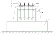
图3为本实用新型的应用示意图;Fig. 3 is the application schematic diagram of the utility model;
图中:1-地脚螺栓In the picture: 1-Anchor bolts
2-定位模具,2.1-定位孔2-positioning mold, 2.1-positioning hole
3-方木3-square wood
4-固定支架,4.1-方形框架,4.2-支腿,4.3-加固杆4- Fixed bracket, 4.1- Square frame, 4.2- Outrigger, 4.3- Reinforcement rod
5-基础承台5-Basic bearing platform
6-基础钢筋6-Basic reinforcement
7-精调构件,7.1-螺母,7.2-螺栓。7- Fine adjustment member, 7.1- Nut, 7.2- Bolt.
具体实施方式Detailed ways
结合附图说明,对本实用新型的具体实施方式作进一步说明:The specific embodiments of the present utility model will be further described with reference to the accompanying drawings:
参照图1-图3,本实用新型提供了一种用于埋设地脚螺栓的定位装置,包括定位模具2、至少两个用于初步调节的方木3、固定支架4和用于精调的精调构件7;1-3, the present utility model provides a positioning device for burying anchor bolts, including a
所述固定支架4包括方形框架4.1和支腿4.2,支腿4.2固定于方形框架4.1四个角的底部,支腿4.2底端固定有精调构件7;The
定位模具2为板状结构,定位模具2上设有定位孔2.1;The
方木3为矩形块状结构;The
固定支架4位于基础承台5的顶部,方木3架设于固定支架4的方形框架4.1的顶部,定位模具2放置于方木3的顶部,地脚螺栓1的顶部穿过于定位模具2的定位孔2.1并通过螺母固定。The
包括螺母7.1和螺栓7.2,螺母7.1和螺栓7.2螺纹连接,螺母7.1固定于固定支架4的支腿4.2底部的一侧。It includes a nut 7.1 and a bolt 7.2, the nut 7.1 and the bolt 7.2 are threadedly connected, and the nut 7.1 is fixed on one side of the bottom of the leg 4.2 of the
固定支架4的支腿4.2通过钢筋套管接长。The outriggers 4.2 of the
固定支架4的两相邻支腿4.2之间均固定有加固杆4.3。Reinforcing rods 4.3 are fixed between two adjacent legs 4.2 of the
固定支架4由螺纹钢筋焊接而成。The
定位模具2用于控制地脚螺栓1的水平相对位置,方木3和固定支架4用于控制地脚螺栓的竖向相对位置。The
方木3由施工废弃材料做成,可以单个支撑或者多个叠加,通过方木3初步调节固定支架4的高度;固定支架4上设有精调构件7,用于精调固定支架4的高度,从而实现地脚螺栓1精准定位。The
精调构件7的螺栓7.2的长度和方木3的高度之和为地脚螺栓1的竖向可调节的最大允许高度。The sum of the length of the bolt 7.2 of the
定位模具2由钢板或者FRP材料制作而成。The positioning die 2 is made of steel plate or FRP material.
本实用新型的应用例:Application example of the present utility model:
1.将固定支架4放于基础承台5的顶部,将定位模具2套装在地脚螺栓1的顶部,在定位模具2与固定支架4的方形框架4.1之间垫放方木3,使得地脚螺栓1的竖向位置初步达到要求;1. Put the
2.调节精调构件7的螺栓7.2,精确调节地脚螺栓1的竖向位置,并拧紧螺母使得地脚螺栓1与定位模具2固定;2. Adjust the bolt 7.2 of the
3.将地脚螺栓1与固定于基础承台5上的基础钢筋6焊接固定;3. Weld the
4.松开地脚螺栓1顶端的螺母,移除定位模具2,再将固定支架4与方木3移除;4. Loosen the nut at the top of the
5.存储固定支架4、方木3和定位模具2以备下次使用。5. Store the
本实用新型的有益之处:Benefit of the present utility model:
本实用新型结构简单可靠,操作方便;大大提高地脚螺栓埋设精度,从而保证建筑工程的施工质量;避免了精度达不到采取纠正措施导致的拖延施工进度,增加人工成本,影响施工质量;可以有效降低施工成本,有效提高施工效率;另外,本实用新型就地取材,制作成本低。The utility model has the advantages of simple and reliable structure and convenient operation; greatly improves the burying accuracy of the anchor bolts, thereby ensuring the construction quality of the construction project; avoids delaying the construction progress, increasing labor costs and affecting the construction quality caused by taking corrective measures if the accuracy is not up to the level; The construction cost is effectively reduced, and the construction efficiency is effectively improved; in addition, the utility model obtains materials on the spot, and the production cost is low.
Claims (4)
Priority Applications (1)
| Application Number | Priority Date | Filing Date | Title |
|---|---|---|---|
| CN202020322982.7U CN211948530U (en) | 2020-03-16 | 2020-03-16 | A positioning device for burying anchor bolts |
Applications Claiming Priority (1)
| Application Number | Priority Date | Filing Date | Title |
|---|---|---|---|
| CN202020322982.7U CN211948530U (en) | 2020-03-16 | 2020-03-16 | A positioning device for burying anchor bolts |
Publications (1)
| Publication Number | Publication Date |
|---|---|
| CN211948530U true CN211948530U (en) | 2020-11-17 |
Family
ID=73179399
Family Applications (1)
| Application Number | Title | Priority Date | Filing Date |
|---|---|---|---|
| CN202020322982.7U Expired - Fee Related CN211948530U (en) | 2020-03-16 | 2020-03-16 | A positioning device for burying anchor bolts |
Country Status (1)
| Country | Link |
|---|---|
| CN (1) | CN211948530U (en) |
Cited By (1)
| Publication number | Priority date | Publication date | Assignee | Title |
|---|---|---|---|---|
| CN115142556A (en) * | 2022-04-06 | 2022-10-04 | 湖南鼎盛绿色建筑集团有限公司 | Assembly type building supporting seat in building engineering and installation method thereof |
-
2020
- 2020-03-16 CN CN202020322982.7U patent/CN211948530U/en not_active Expired - Fee Related
Cited By (2)
| Publication number | Priority date | Publication date | Assignee | Title |
|---|---|---|---|---|
| CN115142556A (en) * | 2022-04-06 | 2022-10-04 | 湖南鼎盛绿色建筑集团有限公司 | Assembly type building supporting seat in building engineering and installation method thereof |
| CN115142556B (en) * | 2022-04-06 | 2024-03-26 | 湖南鼎盛绿色建筑集团有限公司 | A kind of prefabricated building support base and its installation method in construction projects |
Similar Documents
| Publication | Publication Date | Title |
|---|---|---|
| CN102127966B (en) | Fixing device for template of cast-in-place reinforced concrete column | |
| CN210216479U (en) | Positioning device for pre-embedding large foundation bolt group | |
| CN110485707A (en) | Wall column formwork blocks levelling device and its construction method | |
| CN112878712A (en) | Compression shear foundation bolt pre-embedding installation device and construction method thereof | |
| CN220432162U (en) | Leveling and supporting device for embedded supporting leg of heavy tower crane | |
| CN116290581A (en) | A temporary support tool for column skeleton reinforcement and its application method | |
| CN215802680U (en) | Steel reinforced column mounting structure | |
| CN206428565U (en) | A kind of concrete set shaped steel formwork support system | |
| CN218952796U (en) | Adjustable kitchen and bathroom hanging die positioning and fixing device | |
| CN111287450A (en) | A beam bottom arching support formwork device | |
| CN202007527U (en) | Cast-in-place steel reinforcing bar concrete column template fixing device | |
| CN110126063A (en) | A kind of tower crane counterweight producing device | |
| CN214739887U (en) | An independently adjustable steel column formwork system column foot device | |
| CN216042743U (en) | Pre-buried installation device of compression shear machine rag bolt | |
| TWM510942U (en) | Precasted concrete foundation for upright shape steel post | |
| CN208633584U (en) | A kind of prefabricated mounting of roof plate supporting frame of wall-attached | |
| CN217000955U (en) | Quick positioner of unsettled anchor slab column base bolt | |
| CN212534193U (en) | A device base that facilitates quick adjustment | |
| CN222935965U (en) | Assembly jig frame of I-steel joint of diaphragm wall reinforcement cage | |
| CN208361753U (en) | A kind of tower crane supporting leg anchoring pre-buried structure and tower crane | |
| CN218970657U (en) | A positioning bracket for concrete hanging formwork | |
| CN222632831U (en) | Clamp device for cast-in-place horizontal tie beam construction | |
| CN224173369U (en) | Hanging die reinforcing device | |
| CN216810639U (en) | Fixing point adjustable device for inclined supporting rod | |
| CN223002642U (en) | A tower crane foundation support device |
Legal Events
| Date | Code | Title | Description |
|---|---|---|---|
| GR01 | Patent grant | ||
| GR01 | Patent grant | ||
| CF01 | Termination of patent right due to non-payment of annual fee | ||
| CF01 | Termination of patent right due to non-payment of annual fee |
Granted publication date: 20201117 |