CN211948010U - A continuous beam hanging basket cantilever cast-in-place temporary consolidation construction structure - Google Patents
A continuous beam hanging basket cantilever cast-in-place temporary consolidation construction structure Download PDFInfo
- Publication number
- CN211948010U CN211948010U CN202020406168.3U CN202020406168U CN211948010U CN 211948010 U CN211948010 U CN 211948010U CN 202020406168 U CN202020406168 U CN 202020406168U CN 211948010 U CN211948010 U CN 211948010U
- Authority
- CN
- China
- Prior art keywords
- block
- pier body
- continuous beam
- hanging basket
- temporary
- Prior art date
- Legal status (The legal status is an assumption and is not a legal conclusion. Google has not performed a legal analysis and makes no representation as to the accuracy of the status listed.)
- Active
Links
Images
Landscapes
- Bridges Or Land Bridges (AREA)
Abstract
本实用新型适用于连续梁挂篮悬臂现浇施工领域,提供了一种连续梁挂篮悬臂现浇临时固结施工结构,包括:墩身;0号块,其内设有预埋管件,所述预埋管件与处于墩身内的预埋管件连通,所述预埋管件用于容放紧固件,且所述紧固件的两端通过锚固装置与0号块连接使紧固件张紧,使得墩身和0号块临时固结;以及临时支座,数量为若干个,安装在所述墩身和0号块之间,本实用新型的有益效果是:其在墩身和0号块施工时预埋波纹管,并将钢绞线置入波纹管内,通过扁锚来调整钢绞线的张紧或放张,以实现墩身和0号块的临时固结或临时固结状态的解除,当连续梁施工完成后,紧固件可以取出重复利用,形式简单,安装及拆除便利。

The utility model is suitable for the field of continuous beam hanging basket cantilever cast-in-situ construction, and provides a continuous beam hanging basket cantilever cast-in-place temporary consolidation construction structure, comprising: a pier body; The pre-embedded pipe fittings are communicated with the pre-embedded pipe fittings in the pier body, the pre-embedded pipe fittings are used to accommodate the fasteners, and the two ends of the fasteners are connected with the No. 0 block through the anchoring device to tension the fasteners , so that the pier body and the No. 0 block are temporarily consolidated; and the number of temporary supports is several, which are installed between the pier body and the No. 0 block. During the construction of the block, the corrugated pipe is pre-embedded, and the steel strand is placed in the corrugated pipe, and the tension or release of the steel strand is adjusted by the flat anchor to realize the temporary consolidation or temporary consolidation of the pier body and No. 0 block. After the construction of the continuous beam is completed, the fasteners can be taken out and reused, the form is simple, and the installation and removal are convenient.
Description
技术领域technical field
本实用新型涉及连续梁挂篮悬臂现浇施工领域,尤其涉及一种连续梁挂篮悬臂现浇临时固结施工结构。The utility model relates to the field of continuous beam hanging basket cantilever cast-in-place construction, in particular to a continuous beam hanging basket cantilever cast-in-place temporary consolidation construction structure.
背景技术Background technique
连续梁挂篮悬臂现浇混凝土施工是常规的方法,中间桥墩顶部与连续梁0号块底部临时固结所用的临时支座设置是否合理科学对成桥后的连续梁受力影响较大。由于连续梁底部与桥梁顶部空间狭小,受限机械切割技术,依靠人工解除临时固结的难度较大。The continuous girder hanging basket cantilever cast-in-situ concrete construction is a conventional method. Whether the temporary support used for the temporary consolidation of the top of the middle pier and the bottom of the continuous girder block 0 is reasonable and scientific, which has a great influence on the force of the continuous girder after the bridge is completed. Due to the narrow space between the bottom of the continuous beam and the top of the bridge and limited mechanical cutting technology, it is difficult to manually release the temporary consolidation.
早期的临时支座一般采用砂筒、硫磺砂浆等方法,但解除临时固结时,由于砂砾摩阻力的存在,砂筒泄砂的稳定性和全桥多个临时固结同步解除较难保证,同时因硫磺砂浆的配方、通电熔解效果和临时支座长时间暴露于自然环境下的老化等原因,通电熔解的可靠性不高,故有解除砂筒、硫磺砂浆临时固结失败的实例。The early temporary supports generally used methods such as sand barrels and sulfur mortar. However, when the temporary consolidation was released, it was difficult to ensure the stability of sand release from the sand barrel and the simultaneous release of multiple temporary consolidations of the whole bridge due to the existence of sand and gravel frictional resistance. At the same time, due to the formula of sulfur mortar, the effect of electrification melting, and the aging of temporary supports exposed to the natural environment for a long time, the reliability of electrification melting is not high, so there are examples of failure of temporary consolidation of the sand cylinder and sulfur mortar.
目前,由于不受空间限制的绳切割技术的发展,临时固结常采用混凝土、钢板等刚性临时支座,但刚性临时支座切割施工较为繁琐,且临时固结和解除临时固结时沉降差异较大,使成桥后的连续梁产生次内力,影响了桥梁受力和耐久性。At present, due to the development of rope cutting technology that is not limited by space, rigid temporary supports such as concrete and steel plates are often used for temporary consolidation. However, the cutting construction of rigid temporary supports is cumbersome, and the settlement difference between temporary consolidation and release of temporary consolidation If it is larger, the secondary internal force will be generated in the continuous beam after the bridge is completed, which will affect the stress and durability of the bridge.
实用新型内容Utility model content
本实用新型实施例的目的在于提供一种连续梁挂篮悬臂现浇临时固结施工结构,旨在解决背景技术中提出的技术问题。The purpose of the embodiments of the present invention is to provide a continuous beam hanging basket cantilever cast-in-place temporary consolidation construction structure, which aims to solve the technical problems raised in the background art.
本实用新型实施例是这样实现的,一种连续梁挂篮悬臂现浇临时固结施工结构,包括:The embodiment of the present utility model is realized in this way, a continuous beam hanging basket cantilever cast-in-place temporary consolidation construction structure, comprising:
墩身;pier body;
0号块,其内设有预埋管件,所述预埋管件与处于墩身内的预埋管件连通,所述预埋管件用于容放紧固件,且所述紧固件的两端通过锚固装置与0号块连接使紧固件张紧,使得墩身和0号块临时固结;以及Block No. 0 has a pre-embedded pipe fitting in it, the pre-embedded pipe fitting communicates with the pre-embedded pipe fitting in the pier body, the pre-embedded pipe fitting is used for accommodating fasteners, and both ends of the fasteners pass through. The anchoring device is connected to block 0 to tension the fasteners to temporarily consolidate the pier body and block 0; and
临时支座,数量为若干个,安装在所述墩身和0号块之间。Temporary supports, several in number, are installed between the pier body and the No. 0 block.
作为本实用新型进一步的方案:所述预埋管件为波纹管,0号块内的波纹管和墩身内的波纹管拼接形成U形结构。As a further solution of the present utility model: the pre-embedded pipe fittings are corrugated pipes, and the corrugated pipes in the No. 0 block and the corrugated pipes in the pier body are spliced to form a U-shaped structure.
作为本实用新型再进一步的方案:所述紧固件为钢绞线,所述钢绞线的两端通过锚固装置张紧。As a further solution of the present invention, the fasteners are steel strands, and both ends of the steel strands are tensioned by anchoring devices.
作为本实用新型再进一步的方案:所述锚固装置包括扁锚和垫板,所述钢绞线的两端通过扁锚和垫板牵拉张紧。As a further solution of the present invention, the anchoring device includes a flat anchor and a backing plate, and both ends of the steel strand are pulled and tensioned by the flat anchor and the backing plate.
作为本实用新型再进一步的方案:所述临时支座和0号块之间通过四氟板密贴。As a further solution of the present invention, the temporary support and the No. 0 block are closely adhered through a tetrafluoro board.
与现有技术相比,本实用新型的有益效果是:其在墩身和0号块施工时预埋波纹管,并将钢绞线置入波纹管内,通过扁锚来调整钢绞线的张紧或放张,以实现墩身和0号块的临时固结或临时固结状态的解除,当连续梁施工完成后,紧固件可以取出重复利用,形式简单,安装及拆除便利,经济效益提高,与现有技术中采用刚性临时支座的方式,无需进行繁琐切割,且不会出现沉降差异大的问题。Compared with the prior art, the beneficial effect of the utility model is that it pre-embeds the corrugated pipe during the construction of the pier body and the No. 0 block, puts the steel strand into the corrugated pipe, and adjusts the tension of the steel strand through the flat anchor. Tighten or stretch to realize the temporary consolidation or release of the temporary consolidation state of the pier body and No. 0 block. After the construction of the continuous beam is completed, the fasteners can be taken out and reused. The form is simple, the installation and removal are convenient, and the economic benefits are Compared with the way of using rigid temporary support in the prior art, there is no need to carry out cumbersome cutting, and the problem of large difference in settlement will not occur.
附图说明Description of drawings
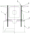
图1为种连续梁挂篮悬臂现浇临时固结施工结构的正视图。Figure 1 is a front view of a continuous beam hanging basket cantilever cast-in-place temporary consolidation construction structure.
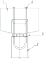
图2为种连续梁挂篮悬臂现浇临时固结施工结构的侧视图。Figure 2 is a side view of a continuous beam hanging basket cantilever cast-in-place temporary consolidation construction structure.
附图中:1-0号块、2-墩身、3-临时支座、4-扁锚、5-钢绞线、6-波纹管。In the attached drawings: 1-0 block, 2-pier body, 3-temporary support, 4-flat anchor, 5-steel strand, 6-corrugated pipe.
具体实施方式Detailed ways
为了使本实用新型的目的、技术方案及优点更加清楚明白,以下结合附图及实施例,对本实用新型进行进一步详细说明。应当理解,此处所描述的具体实施例仅仅用以解释本实用新型,并不用于限定本实用新型。In order to make the purpose, technical solutions and advantages of the present utility model more clearly understood, the present utility model will be further described in detail below with reference to the accompanying drawings and embodiments. It should be understood that the specific embodiments described herein are only used to explain the present invention, and are not intended to limit the present invention.
以下结合具体实施例对本实用新型的具体实现进行详细描述。The specific implementation of the present invention will be described in detail below with reference to specific embodiments.
如图1~2所示,为本实用新型一个实施例提供的一种连续梁挂篮悬臂现浇临时固结施工结构的结构图,包括墩身2、0号块1和临时支座3,所述0号块1内设有预埋管件,所述预埋管件与处于墩身2内的预埋管件连通,所述预埋管件用于容放紧固件,且所述紧固件的两端通过锚固装置与0号块1连接使紧固件张紧使得墩身2和0号块1临时固结;所述临时支座3的数量为若干个,临时支座3设置在所述墩身2和0号块1之间。As shown in Figures 1-2, a structural diagram of a continuous beam hanging basket cantilever cast-in-place temporary consolidation construction structure provided by an embodiment of the present utility model includes a
本实用新型实施例中,0号块1和墩身2在施工时均设有预埋管件,此处的预埋管件保持连通,并用于放置紧固件,紧固件从预埋管件的一端穿入另端穿出,紧固件的两端使用锚固装置张紧后,能实现墩身2和0号块1临时固结,当连续梁施工完成后,紧固件可以取出重复利用,形式简单,安装及拆除便利,与现有技术中采用刚性临时支座的方式,无需进行繁琐切割,且不会出现沉降差异大的问题。In the embodiment of the present utility model, the No. 0
如图1~2所示,作为本实用新型一个优选的实施例,所述预埋管件为波纹管6,0号块1内的波纹管6和墩身2内的波纹管6拼接形成U形结构。As shown in Figures 1-2, as a preferred embodiment of the present utility model, the pre-embedded pipe fitting is a corrugated pipe 6, and the corrugated pipe 6 in the No. 0
本实施例的一种情况中,所述波纹管6为塑料波纹管,而且,墩身2内的波纹管6为U形,并与0号块1内的波纹管6位置相对,本实施例中,使用塑料波纹管作为预埋管件,成本较低。In one case of this embodiment, the corrugated pipe 6 is a plastic corrugated pipe, and the corrugated pipe 6 in the
如图1~2所示,作为本实用新型另一个优选的实施例,所述紧固件为钢绞线5,所述钢绞线5的两端通过锚固装置张紧。As shown in Figures 1-2, as another preferred embodiment of the present invention, the fastener is a
在本实施例的一种情况中,钢绞线5的数量既可以为一根,也可以为多根,可以根据实际施工时的要求强度进行选用,本实施例不对其进行具体的限定。In one case of this embodiment, the number of
如图1~2所示,作为本实用新型另一个优选的实施例,所述锚固装置包括扁锚4和垫板,所述钢绞线5的两端通过扁锚4和垫板牵拉张紧。As shown in Figures 1-2, as another preferred embodiment of the present invention, the anchoring device includes a
本实施例中,通过调整扁锚4的挤压头或者调解螺母等,可以调整钢绞线5的张紧状态,实现张紧或者放张,以满足使用需求,在本实施例的一种情况中,扁锚4的规格可以为M15-N,当然在实际应用时,也可以选用其他形式的预应力锚具,本实施例在此不对其进行具体的限定。In this embodiment, by adjusting the extrusion head of the
如图1~2所示,作为本实用新型另一个优选的实施例,所述临时支座3和0号块1之间通过四氟板密贴。As shown in Figures 1 to 2, as another preferred embodiment of the present invention, the
四氟板具有优良的耐候性、耐腐蚀、机械性质较软等性能,其通过专用胶水密贴在临时支座3和0号块1之间时,不仅能有效防止雨水的侵蚀,同时还具有一定的减震性能。The PTFE board has excellent weather resistance, corrosion resistance, soft mechanical properties and other properties. When it is tightly attached between the
如图1~2所示,本实用新型实施例还提供了一种连续梁挂篮悬臂现浇临时固结施工方法,包括以下步骤:As shown in Figures 1-2, an embodiment of the present invention also provides a continuous beam hanging basket cantilever cast-in-place temporary consolidation construction method, comprising the following steps:
墩身2施工,进行墩身2施工时,在所述墩身2内预埋波纹管6;During the construction of the
0号块1施工时,在0号块1内预埋波纹管6,且墩身2内的波纹管6和0号块1内的波纹管6保持连通,然后进行临时支座3的施工;During construction of No. 0
将钢绞线5穿束通过墩身2及0号块1内的波纹管6,在钢绞线5的两端安装扁锚4和垫板,张拉钢绞线5使其张紧并进行锚固;Pass the
然后进行连续梁悬臂的浇筑,并按照设定要求进行养护。Then the continuous beam cantilever is poured and cured according to the set requirements.
本实施例中,墩身2、0号块1在前期的钢筋捆扎、以及后期的混凝土浇筑、养护等与现有技术相同,为了简化技术方案,在本实施例中均不进行具体的说明,但不影响本申请技术方案的完整性。In this embodiment, the bundling of steel bars in the early stage of the
如图1~2所示,作为本实用新型一个优选的实施例,在进行临时支座3的施工时,还在临时支座3和0号块1之间采用四氟板密贴。As shown in Figures 1-2, as a preferred embodiment of the present utility model, when the
四氟板具有优良的耐候性、耐腐蚀、机械性质较软等性能,其通过专用胶水密贴在临时支座3和0号块1之间时,不仅能有效防止雨水的侵蚀,同时还具有一定的减震性能。The PTFE board has excellent weather resistance, corrosion resistance, soft mechanical properties and other properties. When it is tightly attached between the
如图1~2所示,作为本实用新型另一个优选的实施例,当完成连续梁悬臂的浇筑合龙之后,放张钢绞线5并将钢绞线5抽出,拆除临时支座3顶部的四氟板,以解除整体临时固结状态,然后向墩身2和0号块1内的波纹管6补浆。As shown in Figures 1 to 2, as another preferred embodiment of the present invention, after the continuous beam cantilever is casted and closed, the
在实际应用时,当连续梁悬臂的浇筑合龙完成之后,通过调整扁锚4的挤压头或者调解螺母等,使得钢绞线5呈现放张状态,同步拆除扁锚4以及对钢绞线5抽出回收,然后拆除临时支座3顶部的四氟板,以解除整体临时固结状态,再向墩身2和0号块1内的波纹管6中补浆,补浆操作与现有技术相同,在此也不进行具体的叙述。In practical application, after the casting of the continuous beam cantilever is completed, by adjusting the extrusion head of the
本实用新型上述实施例中,公开了一种连续梁挂篮悬臂现浇临时固结施工结构,并基于该连续梁挂篮悬臂现浇临时固结施工结构提出了一种连续梁挂篮悬臂现浇临时固结施工方法,其在墩身2和0号块1施工时预埋波纹管6,并将钢绞线5置入波纹管6内,通过扁锚4来调整钢绞线5的张紧或放张,以实现墩身2和0号块1的临时固结或临时固结状态的解除,当连续梁施工完成后,紧固件可以取出重复利用,形式简单,安装及拆除便利,经济效益提高,与现有技术中采用刚性临时支座的方式,无需进行繁琐切割,且不会出现沉降差异大的问题。In the above-mentioned embodiments of the present utility model, a continuous beam hanging basket cantilever cantilever cast-in-place temporary consolidation construction structure is disclosed, and based on the continuous beam hanging basket cantilever cast-in-place temporary consolidation construction structure, a continuous beam hanging basket cantilever cast-in-place temporary consolidation construction structure is proposed. The construction method of pouring temporary consolidation, which pre-embeds the corrugated pipe 6 during the construction of the
以上所述仅为本实用新型的较佳实施例而已,并不用以限制本实用新型,凡在本实用新型的精神和原则之内所作的任何修改、等同替换和改进等,均应包含在本实用新型的保护范围之内。The above are only preferred embodiments of the present invention, and are not intended to limit the present invention. Any modifications, equivalent replacements and improvements made within the spirit and principles of the present invention shall be included in the present invention. within the scope of protection of the utility model.
Claims (5)
Priority Applications (1)
| Application Number | Priority Date | Filing Date | Title |
|---|---|---|---|
| CN202020406168.3U CN211948010U (en) | 2020-03-26 | 2020-03-26 | A continuous beam hanging basket cantilever cast-in-place temporary consolidation construction structure |
Applications Claiming Priority (1)
| Application Number | Priority Date | Filing Date | Title |
|---|---|---|---|
| CN202020406168.3U CN211948010U (en) | 2020-03-26 | 2020-03-26 | A continuous beam hanging basket cantilever cast-in-place temporary consolidation construction structure |
Publications (1)
| Publication Number | Publication Date |
|---|---|
| CN211948010U true CN211948010U (en) | 2020-11-17 |
Family
ID=73186086
Family Applications (1)
| Application Number | Title | Priority Date | Filing Date |
|---|---|---|---|
| CN202020406168.3U Active CN211948010U (en) | 2020-03-26 | 2020-03-26 | A continuous beam hanging basket cantilever cast-in-place temporary consolidation construction structure |
Country Status (1)
| Country | Link |
|---|---|
| CN (1) | CN211948010U (en) |
Cited By (1)
| Publication number | Priority date | Publication date | Assignee | Title |
|---|---|---|---|---|
| CN111287097A (en) * | 2020-03-26 | 2020-06-16 | 中铁上海工程局集团有限公司 | Continuous beam hanging basket cantilever cast-in-place temporary consolidation construction structure and method |
-
2020
- 2020-03-26 CN CN202020406168.3U patent/CN211948010U/en active Active
Cited By (1)
| Publication number | Priority date | Publication date | Assignee | Title |
|---|---|---|---|---|
| CN111287097A (en) * | 2020-03-26 | 2020-06-16 | 中铁上海工程局集团有限公司 | Continuous beam hanging basket cantilever cast-in-place temporary consolidation construction structure and method |
Similar Documents
| Publication | Publication Date | Title |
|---|---|---|
| CN102352597B (en) | Prestressed ultrahigh-performance concrete continuous box girder bridge and construction method thereof | |
| CN103321430B (en) | Pre-stressed carbon fiber sheet material is reinforced greatly across the construction method of concrete structure | |
| CN101691742B (en) | Construction method for back cable-balancing single-side cantilever concreted beam bodies of slant-legged rigid frame bridges | |
| CN204491425U (en) | A kind of external prestressing strengthening structure of T-shaped bridge diaphragm | |
| CN108914760A (en) | Consider the box beam and its prestress strengthening method of external prestressing strengthening | |
| CN109137739B (en) | Tower anchor-pier anchor combined rapid construction method of self-anchored suspension bridge | |
| CN104805770B (en) | A kind of it is applicable to the mountain area occasional passage erection method across valley | |
| CN208151833U (en) | A kind of construction of novel RC-masonry combination arch bridge | |
| CN111424555B (en) | Temporary consolidation system for bridge pier beams of continuous beam, continuous beam bridge and construction method | |
| CN108374320A (en) | A kind of construction and construction method of novel RC-masonry combination arch bridge | |
| JP3635004B2 (en) | Bridge cantilever construction method | |
| CN108457195A (en) | A kind of mixed composite beam bridge pre-bending construction method of steel- | |
| CN113062233A (en) | Pre-tensioning method prestressed steel plate-concrete reinforcing method for box girder | |
| CN110905198B (en) | A construction method for reinforcing a steel stranded wire template and a reinforcing anchor device | |
| CN218083367U (en) | A construction device for municipal road and bridge pre-tensioning prestress release | |
| KR101339367B1 (en) | Fabrication and reinforcing method for pre-flex girder | |
| CN201459776U (en) | Rock slope prestressed anchor cable testing and tensioning device | |
| CN111287097A (en) | Continuous beam hanging basket cantilever cast-in-place temporary consolidation construction structure and method | |
| CN109371994B (en) | Civil engineering side slope anchoring device | |
| CN209128886U (en) | A kind of tower beam thrust attachment device for quickly building construction for self-anchored suspension bridge | |
| CN208604499U (en) | Limit the built-in concrete beam bridge steel reinforced concrete anchoring piece of Local Cracking | |
| CN107165059A (en) | A kind of construction method of the anti-bend reinforced device of bridge prestress high-strength steel cord | |
| CN201660850U (en) | Temporary anchoring structure during construction of a self-anchored bridge | |
| CN212404845U (en) | Temporary continuous beam pier beam consolidation system and continuous beam bridge | |
| KR100400189B1 (en) | Method enlarging the thickness of lower part of concrete structure |
Legal Events
| Date | Code | Title | Description |
|---|---|---|---|
| GR01 | Patent grant | ||
| GR01 | Patent grant |