CN211930004U - Convenient block terminal of dismantling change - Google Patents
Convenient block terminal of dismantling change Download PDFInfo
- Publication number
- CN211930004U CN211930004U CN202020715739.1U CN202020715739U CN211930004U CN 211930004 U CN211930004 U CN 211930004U CN 202020715739 U CN202020715739 U CN 202020715739U CN 211930004 U CN211930004 U CN 211930004U
- Authority
- CN
- China
- Prior art keywords
- box
- movable
- plate
- clamping
- convenient
- Prior art date
- Legal status (The legal status is an assumption and is not a legal conclusion. Google has not performed a legal analysis and makes no representation as to the accuracy of the status listed.)
- Expired - Fee Related
Links
- 238000003466 welding Methods 0.000 claims description 4
- 239000000853 adhesive Substances 0.000 claims description 3
- 230000001070 adhesive effect Effects 0.000 claims description 3
- 230000000694 effects Effects 0.000 abstract description 11
- 238000012423 maintenance Methods 0.000 abstract description 11
- 230000006978 adaptation Effects 0.000 abstract 2
- 101100491335 Caenorhabditis elegans mat-2 gene Proteins 0.000 description 3
- 230000002159 abnormal effect Effects 0.000 description 1
- 230000004075 alteration Effects 0.000 description 1
- 230000009286 beneficial effect Effects 0.000 description 1
- 238000011161 development Methods 0.000 description 1
- 238000012986 modification Methods 0.000 description 1
- 230000004048 modification Effects 0.000 description 1
- 238000012544 monitoring process Methods 0.000 description 1
- 238000006467 substitution reaction Methods 0.000 description 1
- 238000010998 test method Methods 0.000 description 1
Images

Landscapes
- Structure Of Telephone Exchanges (AREA)
Abstract
The utility model discloses a block terminal of convenient dismantlement change, including placing the board, the top of placing the board is equipped with the box, the bottom of box is equipped with the cardboard, the fixed slot with cardboard looks adaptation is seted up at the top of placing the board, the draw-in groove has all been seted up to the both sides of box, the both sides of placing the board top all are equipped with the movable box, the inner chamber of movable box is equipped with the movable plate, the spout with the movable plate looks adaptation is all seted up to the top and the bottom of movable box inner chamber, the inboard of movable plate is equipped with the kelly, the inboard of kelly runs through and extends to the surface of movable box, the draw-in groove joint on the inboard of kelly and the box. The utility model discloses a place board, movable box, draw-in groove, cardboard, fixed slot, spring, pull rod, pull ring, spout, movable plate and kelly and mutually support, can play the effect of convenient to detach maintenance to the block terminal when the block terminal is using.
Description
Technical Field
The utility model relates to a block terminal technical field specifically is a convenient block terminal of dismantling and changing.
Background
The power distribution cabinet (box) is a final-stage device of a power distribution system, is a general name of a motor control center and is used in occasions with dispersed loads and less loops; motor control centers are used in load concentration and loop-rich applications, where they distribute the power from a circuit of a higher level of distribution equipment to nearby loads, which provide protection, monitoring and control of the loads.
Along with the progress of the times, the development of science and technology, the block terminal is also widely used by people, and when the block terminal was used for a long time, the situation that the block terminal can appear damaging needs the staff to maintain, but, the current distribution box of present market flow is loaded down with trivial details when dismantling to the staff of not being convenient for dismantles the situation of maintenance.
SUMMERY OF THE UTILITY MODEL
An object of the utility model is to provide a convenient block terminal of dismantling and changing possesses the advantage of playing the convenient to detach maintenance to the block terminal, has solved the loaded down with trivial details problem of flow when dismantling the maintenance of current block terminal.
In order to achieve the above object, the utility model provides a following technical scheme: a distribution box convenient to disassemble and replace comprises a placing plate, a box body is arranged at the top of the placing plate, the bottom of the box body is provided with a clamping plate, the top of the placing plate is provided with a fixing groove matched with the clamping plate, the two sides of the box body are both provided with a clamping groove, the two sides of the top of the placing plate are both provided with a movable box, the inner cavity of the movable box is provided with a movable plate, the top and the bottom of the inner cavity of the movable box are both provided with sliding chutes matched with the movable plate, the inner side of the moving plate is provided with a clamping rod, the inner side of the clamping rod penetrates through and extends to the surface of the movable box, the inner side of the clamping rod is clamped with the clamping groove on the box body, springs are arranged at the joints of the top and the bottom of the outer side of the movable plate and the movable box, the outer side of the moving plate is provided with a pull rod, the outer side of the pull rod penetrates through the outer side of the moving box and extends to the outer side of the moving box, and the outer side of the pull rod is provided with a pull ring.
Preferably, the bottom of the placing plate is provided with a non-slip mat, and the joint of the top of the non-slip mat and the placing plate is fixedly connected through an adhesive.
Preferably, the top of the box body is provided with a rain baffle, and the joint of the bottom of the rain baffle and the box body is fixedly connected in a welding mode.
Preferably, the joint of the inner side of the moving plate and the clamping rod is fixedly connected through a connecting block, and the outer side of the clamping rod is located at the center of the inner side of the moving plate.
Preferably, the number of the sliding grooves is two, and the two sliding grooves are identical in shape and size.
Compared with the prior art, the beneficial effects of the utility model are as follows:
1. the utility model discloses a place board, movable box, draw-in groove, cardboard, fixed slot, spring, pull rod, pull ring, spout, movable plate and kelly and mutually support, can play the effect of convenient to detach maintenance to the block terminal when using, it is loaded down with trivial details to have avoided current distribution case flow when dismantling to the staff of being not convenient for dismantles the situation of maintenance, is fit for using widely.
2. The utility model can fix the clamping rod through the connecting block, so that the clamping rod has better effect when in use, and the situation that the clamping rod is loosened when in use is avoided, thereby leading to the situation that the clamping rod falls off when in use;
the distribution box can be protected from rain through the rain shield, so that the distribution box has a better effect in use, and the condition that rainwater enters the distribution box to cause the distribution box to be incapable of being normally used is avoided;
through the slipmat, can play fixed effect to the block terminal, the block terminal effect is better when using like this, has avoided the block terminal situation that removes to appear when using to lead to the situation that block terminal result of use is not good.
Drawings
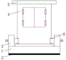
FIG. 1 is a schematic structural view of the present invention;
FIG. 2 is a schematic view of the structure of the inner cavity of the placing plate of the present invention;
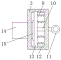
fig. 3 is a schematic view of the structure of the inner cavity of the movable box of the present invention.
In the figure: 1. placing the plate; 2. a non-slip mat; 3. a movable box; 4. a box body; 5. a rain shield; 6. a card slot; 7. clamping a plate; 8. fixing grooves; 9. a spring; 10. a pull rod; 11. a pull ring; 12. a chute; 13. moving the plate; 14. a clamping rod; 15. and (4) connecting the blocks.
Detailed Description
The technical solutions in the embodiments of the present invention will be described clearly and completely with reference to the accompanying drawings in the embodiments of the present invention, and it is obvious that the described embodiments are only some embodiments of the present invention, not all embodiments. Based on the embodiments in the present invention, all other embodiments obtained by a person skilled in the art without creative work belong to the protection scope of the present invention.
In the description of the present invention, it should be noted that the terms "upper", "lower", "inner", "outer", "front end", "rear end", "both ends", "one end", "the other end", and the like indicate orientations or positional relationships based on the orientations or positional relationships shown in the drawings, and are only for convenience of description and simplification of description, but do not indicate or imply that the device or element to be referred must have a specific orientation, be constructed in a specific orientation, and be operated, and thus, should not be construed as limiting the present invention. Furthermore, the terms "first" and "second" are used for descriptive purposes only and are not to be construed as indicating or implying relative importance.
In the description of the present invention, it is to be noted that, unless otherwise explicitly specified or limited, the terms "mounted", "provided", "connected", and the like are to be construed broadly, such as "connected", which may be fixedly connected, detachably connected, or integrally connected; can be mechanically or electrically connected; they may be connected directly or indirectly through intervening media, or they may be interconnected between two elements. The specific meaning of the above terms in the present invention can be understood in specific cases to those skilled in the art.
The standard parts used in the application document can be purchased from the market, and can be customized according to the description of the specification and the description of the attached drawings, the specific connection mode of each part adopts conventional means such as mature bolts, rivets, welding and the like in the prior art, and machines, parts and equipment adopt conventional models in the prior art.
The utility model discloses a place board 1, slipmat 2, movable box 3, box 4, weather shield 5, draw-in groove 6, cardboard 7, fixed slot 8, spring 9, pull rod 10, pull ring 11, spout 12, movable plate 13, kelly 14 and connecting block 15 part and be the parts that general standard or technical personnel in the field know, its structure and principle all are that this technical personnel all can learn through the technical manual or learn through conventional test method.
Referring to fig. 1-3, a distribution box convenient for disassembly and replacement comprises a placing plate 1, wherein the bottom of the placing plate 1 is provided with a non-slip mat 2, the joint of the top of the non-slip mat 2 and the placing plate 1 is fixedly connected through an adhesive, the non-slip mat 2 can fix the distribution box, so that the distribution box has better effect in use, and the distribution box is prevented from moving in use, thereby causing poor use effect of the distribution box, the top of the placing plate 1 is provided with a box body 4, the top of the box body 4 is provided with a rain shield 5, the distribution box can be shielded from rain through the rain shield 5, so that the distribution box has better effect in use, thereby preventing rainwater from entering the distribution box and causing abnormal use, the joint of the bottom of the rain shield 5 and the box body 4 is fixedly connected through a welding mode, the bottom of the box body 4 is provided with a clamping plate 7, the top of the placing plate 1 is provided with a fixed groove 8 matched with the clamping plate 7, the two sides of the box body 4 are provided with clamping grooves 6, the two sides of the top of the placing plate 1 are provided with movable boxes 3, the inner cavity of each movable box 3 is provided with a movable plate 13, the top and the bottom of the inner cavity of each movable box 3 are provided with sliding grooves 12 matched with the movable plates 13, the number of the sliding grooves 12 is two, the shapes and the sizes of the two sliding grooves 12 are consistent, the inner side of each movable plate 13 is provided with a clamping rod 14, the connecting part of the inner side of each movable plate 13 and the clamping rod 14 is fixedly connected through a connecting block 15, the clamping rod 14 can be fixed through the connecting block 15, the clamping rod 14 has a better effect when in use, the situation that the clamping rod 14 is loosened when in use is avoided, so that the clamping rod 14 falls off when in use, the outer side of the clamping rod 14 is positioned at the center of the inner side of the movable plate 13, and the inner, draw-in groove 6 joint on the inboard of kelly 14 and the box 4, the top in the movable plate 13 outside and the junction of bottom and movable box 3 are provided with spring 9, and the outside of movable plate 13 is equipped with pull rod 10, and the outside of pull rod 10 runs through and extends to the outside of movable box 3, and the outside of pull rod 10 is equipped with pull ring 11, the utility model discloses a place board 1, movable box 3, box 4, draw-in groove 6, cardboard 7, fixed slot 8, spring 9, pull rod 10, pull ring 11, spout 12, movable plate 13 and kelly 14 and mutually support, can be when the block terminal uses, can play the effect of convenient to detach maintenance to the block terminal, it is loaded down with trivial details when dismantling to have avoided current distribution box to be not convenient for the staff to dismantle the situation of maintenance, be fit for using widely.
When dismantling the maintenance, pulling pull ring 11, drive pull rod 10 through pull ring 11 and outwards remove, drive movable plate 13 and outwards remove through pull rod 10, spout 12 cooperation movable plate 13 through the movable box 3 removes, drive kelly 14 and outwards remove through movable plate 13, when kelly 14 shifts out draw-in groove 6 on the box 4, cardboard 7 on the box 4 is taken out from placing in the fixed slot 8 on board 1, can dismantle the maintenance to box 4, after the maintenance is accomplished, cardboard 7 on the box 4 is placed in placing fixed slot 8 on board 1, loosen pull ring 11, spring 9's inertia drives the aforesaid simultaneously and resets, can normal use.
Although embodiments of the present invention have been shown and described, it will be appreciated by those skilled in the art that changes, modifications, substitutions and alterations can be made in these embodiments without departing from the principles and spirit of the invention, the scope of which is defined in the appended claims and their equivalents.
Claims (5)
1. The utility model provides a convenient block terminal of dismantling and changing, is including placing board (1), its characterized in that: the top of the placing plate (1) is provided with a box body (4), the bottom of the box body (4) is provided with a clamping plate (7), the top of the placing plate (1) is provided with a fixing groove (8) matched with the clamping plate (7), two sides of the box body (4) are respectively provided with a clamping groove (6), two sides of the top of the placing plate (1) are respectively provided with a movable box (3), an inner cavity of each movable box (3) is provided with a movable plate (13), the top and the bottom of the inner cavity of each movable box (3) are respectively provided with a sliding groove (12) matched with the corresponding movable plate (13), the inner side of each movable plate (13) is provided with a clamping rod (14), the inner side of each clamping rod (14) penetrates through and extends to the surface of each movable box (3), the inner side of each clamping rod (14) is clamped with the clamping groove (6) on the box body (4), and the joints of the top and the bottom of the outer side of each, the outer side of the moving plate (13) is provided with a pull rod (10), the outer side of the pull rod (10) penetrates through and extends to the outer side of the movable box (3), and the outer side of the pull rod (10) is provided with a pull ring (11).
2. The distribution box convenient to disassemble and replace according to claim 1, characterized in that: the bottom of the placing plate (1) is provided with an anti-slip pad (2), and the joint of the top of the anti-slip pad (2) and the placing plate (1) is fixedly connected through an adhesive.
3. The distribution box convenient to disassemble and replace according to claim 1, characterized in that: the top of box (4) is equipped with weather shield (5), the junction of the bottom of weather shield (5) and box (4) is through welding form fixed connection.
4. The distribution box convenient to disassemble and replace according to claim 1, characterized in that: the connection part of the inner side of the moving plate (13) and the clamping rod (14) is fixedly connected through a connecting block (15), and the outer side of the clamping rod (14) is located at the center of the inner side of the moving plate (13).
5. The distribution box convenient to disassemble and replace according to claim 1, characterized in that: the number of the sliding grooves (12) is two, and the shapes and the sizes of the two sliding grooves (12) are consistent.
Priority Applications (1)
| Application Number | Priority Date | Filing Date | Title |
|---|---|---|---|
| CN202020715739.1U CN211930004U (en) | 2020-05-06 | 2020-05-06 | Convenient block terminal of dismantling change |
Applications Claiming Priority (1)
| Application Number | Priority Date | Filing Date | Title |
|---|---|---|---|
| CN202020715739.1U CN211930004U (en) | 2020-05-06 | 2020-05-06 | Convenient block terminal of dismantling change |
Publications (1)
| Publication Number | Publication Date |
|---|---|
| CN211930004U true CN211930004U (en) | 2020-11-13 |
Family
ID=73327853
Family Applications (1)
| Application Number | Title | Priority Date | Filing Date |
|---|---|---|---|
| CN202020715739.1U Expired - Fee Related CN211930004U (en) | 2020-05-06 | 2020-05-06 | Convenient block terminal of dismantling change |
Country Status (1)
| Country | Link |
|---|---|
| CN (1) | CN211930004U (en) |
Cited By (1)
| Publication number | Priority date | Publication date | Assignee | Title |
|---|---|---|---|---|
| CN116711709A (en) * | 2023-06-07 | 2023-09-08 | 湖北集防科技有限公司 | A solar street light bird repelling device |
-
2020
- 2020-05-06 CN CN202020715739.1U patent/CN211930004U/en not_active Expired - Fee Related
Cited By (1)
| Publication number | Priority date | Publication date | Assignee | Title |
|---|---|---|---|---|
| CN116711709A (en) * | 2023-06-07 | 2023-09-08 | 湖北集防科技有限公司 | A solar street light bird repelling device |
Similar Documents
| Publication | Publication Date | Title |
|---|---|---|
| CN202772496U (en) | Tool adapted to mount and dismount bird repeller in electrified state | |
| CN205464289U (en) | Cut mouth of a river equipment | |
| CN210222852U (en) | Office entrance guard equipment convenient to dismantle | |
| CN209896820U (en) | Dust removal motor fan housing | |
| CN211422402U (en) | Security door convenient to maintenance | |
| CN211088791U (en) | Novel power distribution cabinet based on internet of things | |
| CN108945017A (en) | A kind of transport device of the uninterruptible power supply with pooling feature | |
| CN210156463U (en) | Battery module convenient to dismantle | |
| CN207518183U (en) | A kind of novel electric power maintained equipment | |
| CN218182436U (en) | Signal acquisition device for battery module, battery module and power battery pack | |
| CN217036552U (en) | Portable cleaning device for high-altitude electric wires | |
| CN211472273U (en) | Anti-toppling traffic sign mounting bracket | |
| CN108831675A (en) | A kind of power transformer dust guard | |
| CN210608255U (en) | A GIS terminal installation device for training | |
| CN213211888U (en) | Dry-type transformer with heat dissipation function | |
| CN209705569U (en) | A kind of single-lamp controller being easily installed | |
| CN214481670U (en) | High efficiency automation waits to protect and assesses isolated plant | |
| CN218033521U (en) | High-efficient convenient shaded pole machine air-out structure | |
| CN201153195Y (en) | Power adaptor housing easy for mounting and dismounting | |
| CN221509392U (en) | Heat radiation structure of energy storage converter | |
| CN210838520U (en) | Switch board convenient to maintenance | |
| CN213449799U (en) | Road construction dust guard of easy dismouting | |
| CN216291724U (en) | Internet data equipment convenient to maintenance | |
| CN216903895U (en) | Power distribution cabinet convenient to wiring | |
| CN213522485U (en) | Plasma generator |
Legal Events
| Date | Code | Title | Description |
|---|---|---|---|
| GR01 | Patent grant | ||
| GR01 | Patent grant | ||
| CF01 | Termination of patent right due to non-payment of annual fee |
Granted publication date: 20201113 Termination date: 20210506 |
|
| CF01 | Termination of patent right due to non-payment of annual fee |