CN211929592U - Aerogenerator storage battery bearing structure - Google Patents
Aerogenerator storage battery bearing structure Download PDFInfo
- Publication number
- CN211929592U CN211929592U CN202021057722.8U CN202021057722U CN211929592U CN 211929592 U CN211929592 U CN 211929592U CN 202021057722 U CN202021057722 U CN 202021057722U CN 211929592 U CN211929592 U CN 211929592U
- Authority
- CN
- China
- Prior art keywords
- battery
- bottom plate
- battery pack
- plate
- wind turbine
- Prior art date
- Legal status (The legal status is an assumption and is not a legal conclusion. Google has not performed a legal analysis and makes no representation as to the accuracy of the status listed.)
- Expired - Fee Related
Links
Images


Classifications
-
- Y—GENERAL TAGGING OF NEW TECHNOLOGICAL DEVELOPMENTS; GENERAL TAGGING OF CROSS-SECTIONAL TECHNOLOGIES SPANNING OVER SEVERAL SECTIONS OF THE IPC; TECHNICAL SUBJECTS COVERED BY FORMER USPC CROSS-REFERENCE ART COLLECTIONS [XRACs] AND DIGESTS
- Y02—TECHNOLOGIES OR APPLICATIONS FOR MITIGATION OR ADAPTATION AGAINST CLIMATE CHANGE
- Y02E—REDUCTION OF GREENHOUSE GAS [GHG] EMISSIONS, RELATED TO ENERGY GENERATION, TRANSMISSION OR DISTRIBUTION
- Y02E60/00—Enabling technologies; Technologies with a potential or indirect contribution to GHG emissions mitigation
- Y02E60/10—Energy storage using batteries
Landscapes
- Battery Mounting, Suspending (AREA)
Abstract
本实用新型涉及一种风力发电机蓄电池组支撑结构,包括支撑架、设置在支撑架内保护电池的防护装置、固定电池位置的定位装置;支撑架包括底板、垂直于底板设置的侧立板、连接侧立板设置的横连板;底板上设有多个均匀间隔放置蓄电池的电池槽、分隔电池槽的分隔条;防护装置包括支撑蓄电池的垫盒和防护电池连接柱的盖帽;定位装置包括一端铰接在底板上与分隔条处于同一竖直面的铰杆、设置在横连板上拉紧铰杆的拉紧装置。本实用新型结构设计合理,通过支撑架与夹紧机构配合,有效的实现了电池组位置的定位,保证了电池组竖直及水平方向的稳定,在保证减震效果的同时,保证了电池组的稳定性。
The utility model relates to a support structure for a wind turbine battery pack, comprising a support frame, a protective device arranged in the support frame to protect the battery, and a positioning device for fixing the position of the battery; the support frame comprises a bottom plate, side vertical plates arranged perpendicular to the bottom plate, The horizontal connecting plate connected to the side vertical plate; the bottom plate is provided with a plurality of battery slots for placing batteries evenly spaced, and the partition bars for separating the battery slots; the protective device includes a pad box for supporting the battery and a cap for protecting the battery connecting column; the positioning device includes One end of the hinge rod is hinged on the bottom plate and is on the same vertical plane as the dividing strip, and a tensioning device is arranged on the horizontal connecting plate to tighten the hinge rod. The utility model has a reasonable structure design. Through the cooperation between the support frame and the clamping mechanism, the positioning of the battery pack can be effectively realized, the stability of the battery pack in the vertical and horizontal directions is ensured, and the shock absorption effect is ensured while the battery pack is ensured. stability.
Description
技术领域technical field
本实用新型涉及蓄电池支撑结构领域,尤其是一种风力发电机蓄电池组支撑结构。The utility model relates to the field of battery support structures, in particular to a wind power generator battery pack support structure.
背景技术Background technique
风力发电机是将风能转换为机械功,机械功带动转子旋转,最终输出交流电的电力设备。风力发电变桨系统后备电源在风力发电机组掉电的情况下提供紧急后备电源完成桨叶的顺桨以保证机组的安全。授权公告号CN205846049U的中国专利文件公开了一种用于风力发电机蓄电池组的固定架,其特征在于:它包括一底板,在所述底板的周边紧固连接多个形成用于放置蓄电池组的凹槽的立板,在所述底板上靠近所述立板的位置间隔对称设置多个立柱,在每两对称布置的所述立柱的顶端共同可拆卸地连接一横梁,位于所述底板周边中部的所述立柱高于位于所述底板周边两侧的所述立柱。在位于所述凹槽内的所述底板上并排均匀设置多个槽体。在所述底板四周靠近所述立板外侧的位置设置有多个螺纹安装孔,每一所述立柱的底端通过螺纹胶与所述螺纹安装孔紧固连接。本实用新型可以重复利用,节能环保,质量轻且散热效果好。但是现有的发电机蓄电池组大多采用已封装好的蓄电池箱拼装而成,在进行固定电池时,大多采用硬性电池盒进行位置固定,部分电池由于过于细长,且在固定过程中,由于装置的误差,不可避免的产生缝隙,造成蓄电池组在使用过程中的振动。A wind turbine is a power device that converts wind energy into mechanical work, which drives the rotor to rotate, and finally outputs alternating current. The backup power supply of the wind turbine pitch system provides an emergency backup power supply in the event of a power failure of the wind turbine to complete the feathering of the blades to ensure the safety of the unit. The Chinese patent document with the authorization bulletin number CN205846049U discloses a fixing frame for the wind turbine battery pack, which is characterized in that: it includes a bottom plate, and a plurality of brackets for placing the battery pack are fastened and connected around the bottom plate. In the vertical plate of the groove, a plurality of vertical columns are arranged symmetrically at intervals near the vertical plate on the bottom plate, and a beam is detachably connected to the top of each two symmetrically arranged vertical columns, which is located in the middle of the periphery of the bottom plate. The uprights are higher than the uprights located on both sides of the periphery of the bottom plate. A plurality of groove bodies are evenly arranged side by side on the bottom plate located in the groove. A plurality of threaded mounting holes are provided around the bottom plate near the outer side of the vertical plate, and the bottom end of each of the uprights is fastened to the threaded mounting holes through thread glue. The utility model can be reused, has energy saving and environmental protection, light weight and good heat dissipation effect. However, most of the existing generator battery packs are assembled with packaged battery boxes. When fixing batteries, most of them use rigid battery boxes for position fixing. Some batteries are too slender and in the fixing process, due to the device The error will inevitably generate gaps, causing the battery pack to vibrate during use.
实用新型内容Utility model content
本实用新型的目的在于提供一种风力发电机蓄电池组支撑结构,用于解决现有风力发电机蓄电池组固定不稳、容易振动损坏电池的问题。The purpose of the utility model is to provide a support structure for the battery pack of a wind power generator, which is used to solve the problems of unstable fixation of the battery pack of the wind power generator and easy vibration and damage to the battery.
为了解决上述问题,本实用新型提供一种风力发电机蓄电池组支撑结构,包括支撑架、设置在所述支撑架内保护电池的防护装置、固定电池位置的定位装置;所述支撑架包括底板、垂直于所述底板设置的侧立板、连接所述侧立板设置的横连板;所述底板上设有多个均匀间隔放置蓄电池的电池槽、分隔所述电池槽的分隔条;所述防护装置包括支撑蓄电池的垫盒和防护电池连接柱的盖帽;所述定位装置包括一端铰接在所述底板上与所述分隔条处于同一竖直面的铰杆、设置在所述横连板上拉紧所述铰杆的拉紧装置。In order to solve the above problems, the present utility model provides a support structure for a wind turbine battery pack, comprising a support frame, a protective device arranged in the support frame to protect the battery, and a positioning device for fixing the position of the battery; the support frame includes a bottom plate, a side vertical plate arranged perpendicular to the bottom plate, and a horizontal connecting plate connected to the side vertical plate; the bottom plate is provided with a plurality of battery slots for placing batteries at even intervals, and partition bars for separating the battery slots; the The protective device includes a cushion box for supporting the battery and a cap for protecting the connecting column of the battery; the positioning device includes a hinge rod whose one end is hinged on the bottom plate and is in the same vertical plane as the dividing strip, and is arranged on the horizontal connecting plate A tensioning device that tightens the hinge rod.
本实用新型提供的风力发电机蓄电池组支撑结构.还具有以下技术特征:The wind turbine battery pack supporting structure provided by the utility model also has the following technical features:
进一步地,所述侧立板可拆卸的设置在所述底板上;所述底板上设有供所述侧立板滑动的滑道。Further, the side upright plate is detachably arranged on the bottom plate; the bottom plate is provided with a slideway for the side upright plate to slide.
进一步地,所述铰杆远离所述底板的一端设有支撑块、平行于所述底板长度方向设置的挡杆;所述拉紧装置包括平行于所述分隔条设置的螺杆、对向设置在所述横连板两侧的两个拉钩;所述支撑块上设有与所述拉钩相匹配的拉环;所述盖帽平行于所述底板长度方向的侧壁上设有与所述挡杆相匹配的杆槽。Further, the end of the hinge rod away from the bottom plate is provided with a support block and a blocking rod arranged parallel to the length direction of the bottom plate; Two pull hooks on both sides of the horizontal connecting plate; the support block is provided with a pull ring matching the pull hook; the side wall of the cap parallel to the length direction of the bottom plate is provided with the blocking rod Matching rod slots.
进一步地,所述侧立板靠近所述电池槽的一侧设有防护支撑电池的垫块。Further, the side of the side upright plate close to the battery slot is provided with a pad for protecting and supporting the battery.
进一步地,所述支撑块与所述分隔条等厚设置;所述支撑块平行于所述分隔条的两侧设有凹凸摩擦面。Further, the support block and the partition strip are provided with the same thickness; the support block is provided with concave-convex friction surfaces on both sides parallel to the partition strip.
进一步地,所述垫盒和所述盖帽接触电池的一侧设有柔性防震块。Further, a flexible shock-proof block is provided on the side of the cushion box and the cap that contacts the battery.
本实用新型具有如下有益效果:本实用新型结构设计合理、结构简单,通过支撑架与夹紧机构配合的作用,有效的实现了电池组位置的定位,保证了电池组竖直及水平方向的稳定,且柔性防护装置的垫盒及盖帽配合进一步在安装中对防护装置进行一定挤压,在保证减震效果的同时,保证了电池组的一体化。The utility model has the following beneficial effects: the utility model has reasonable structural design and simple structure, and through the cooperation between the support frame and the clamping mechanism, the positioning of the battery pack is effectively realized, and the stability of the battery pack in the vertical and horizontal directions is ensured , and the cushion box and cap of the flexible protective device further squeeze the protective device to a certain extent during installation, which ensures the integration of the battery pack while ensuring the shock absorption effect.
附图说明Description of drawings
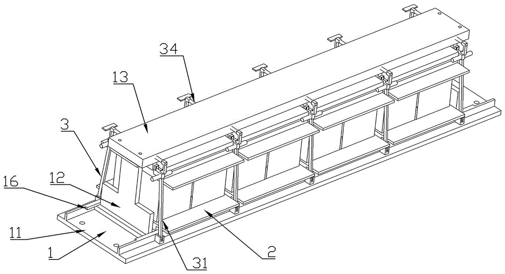
图1为本实用新型实施例的结构示意图;Fig. 1 is the structural representation of the utility model embodiment;
图2为本实用新型实施例的爆炸结构示意图;Fig. 2 is the exploded structure schematic diagram of the embodiment of the present utility model;
图中:1-支撑架,11-底板,12-侧立板,13-横连板,14-电池槽,15-分隔条,16-滑道,2-防护装置,21-垫盒,22-盖帽,221-杆槽,3-定位装置,31-铰杆,32-支撑块,321-拉环,33-挡杆,34-拉紧装置,341-螺杆,342-拉钩。In the figure: 1-support frame, 11-bottom plate, 12-side vertical plate, 13-transverse connecting plate, 14-battery slot, 15-dividing strip, 16-slideway, 2-protection device, 21-pad box, 22 - Cap, 221 - Rod groove, 3 - Positioning device, 31 - Hinge rod, 32 - Support block, 321 - Pull ring, 33 - Stop lever, 34 - Tension device, 341 - Screw rod, 342 - Pull hook.
具体实施方式Detailed ways
下文中将参考附图并结合实施例来详细说明本实用新型。需要说明的是,在不冲突的情况下,本实用新型中的实施例及实施例中的特征可以相互组合。Hereinafter, the present invention will be described in detail with reference to the accompanying drawings and in conjunction with the embodiments. It should be noted that the embodiments of the present invention and the features of the embodiments may be combined with each other under the condition of no conflict.
如图1、图2所示的本实用新型的风力发电机蓄电池组支撑结构的一个实施例中,包括支撑架1、设置在支撑架1内保护电池的防护装置2、固定电池位置的定位装置3;支撑架1包括底板11、垂直于底板11设置的侧立板12、连接侧立板12设置的横连板13;底板11上设有多个均匀间隔放置蓄电池的电池槽14、分隔电池槽14的分隔条15;防护装置2包括支撑蓄电池的垫盒21和防护电池连接柱的盖帽22;定位装置3包括一端铰接在底板11上与分隔条15处于同一竖直面的铰杆31、设置在横连板13上拉紧铰杆31的拉紧装置34。通过设计防护电池的防护装置,在对电池进行固定的同时加设防护层,并通过铰杆与拉紧装置进一步保证装置与现有支撑架的连接稳固度,有效的提高了蓄电池组在使用时的稳定性和防震性能。As shown in Figures 1 and 2, an embodiment of the wind turbine battery pack support structure of the present invention includes a support frame 1, a protective device 2 arranged in the support frame 1 to protect the battery, and a positioning device for fixing the position of the battery 3; the support frame 1 includes a
具体而言,侧立板12可拆卸的设置在底板11上;底板11上设有供侧立板12滑动的滑道16。通过将侧立板滑动设置在底板上,进一步提高支撑架的拆解能力,降低设备搬运过程的空间需求。Specifically, the side
具体而言,铰杆31远离底板11的一端设有支撑块32、平行于底板11长度方向设置的挡杆33;拉紧装置34包括平行于分隔条15设置的螺杆341、对向设置在横连板13两侧的两个拉钩342;支撑块32上设有与拉钩342相匹配的拉环321;盖帽22平行于底板11长度方向的侧壁上设有与挡杆33相匹配的杆槽221。通过在电池组间分隔条的同一竖直面设置支撑块有效的确定了电池组之间的相对位置,且通过挡杆和拉紧装置的配合进一步对电池组进行挤压固定,进一步对电池组顶部水平方向位置进行限定,保证电池组的位置的相对稳定。Specifically, the end of the
具体而言,侧立板12靠近电池槽14的一侧设有防护支撑电池的垫块。通过滑动的侧立板与支撑垫块配合有对水平方向的电池组进行夹持支撑,有效的降低电池组水平方向的位移。Specifically, the side of the side
具体而言,支撑块32与分隔条15等厚设置;支撑块32平行于分隔条15的两侧设有凹凸摩擦面。通过在支撑块两侧设计摩擦面有效的保证支撑块对电池组顶部的位置定位的同时,进一步提高电池组的一体性,保证支撑架的稳定性。Specifically, the
具体而言,垫盒21和盖帽22接触电池的一侧设有柔性防震块。Specifically, the side of the pad box 21 and the
工作原理:使用者将需要的电池组套设垫盒21和盖帽22后,放置在电池槽14内,固定侧立板12且压盖横连板13后,拧紧螺杆341,铰杆31在拉钩342与拉环321的配合作用下进行紧固,挡杆33对杆槽221进行挤压,进一步保证电池组顶部的位置稳定。Working principle: After the user sets the required battery pack in the cushion box 21 and the
最后应说明的是:以上实施例仅用以说明本实用新型的技术方案,而非对其限制;尽管参照前述实施例对本实用新型进行了详细的说明,本领域的普通技术人员应当理解:其依然可以对前述各实施例所记载的技术方案进行修改,或者对其中部分技术特征进行等同替换;而这些修改或者替换,并不使相应技术方案的本质脱离本实用新型各实施例技术方案的精神和范围。Finally, it should be noted that the above embodiments are only used to illustrate the technical solutions of the present utility model, but not to limit them; although the present utility model has been described in detail with reference to the foregoing embodiments, those of ordinary skill in the art should understand that: It is still possible to modify the technical solutions recorded in the foregoing embodiments, or perform equivalent replacements to some of the technical features; and these modifications or replacements do not make the essence of the corresponding technical solutions depart from the spirit of the technical solutions of the embodiments of the present invention and range.
Claims (6)
Priority Applications (1)
| Application Number | Priority Date | Filing Date | Title |
|---|---|---|---|
| CN202021057722.8U CN211929592U (en) | 2020-06-10 | 2020-06-10 | Aerogenerator storage battery bearing structure |
Applications Claiming Priority (1)
| Application Number | Priority Date | Filing Date | Title |
|---|---|---|---|
| CN202021057722.8U CN211929592U (en) | 2020-06-10 | 2020-06-10 | Aerogenerator storage battery bearing structure |
Publications (1)
| Publication Number | Publication Date |
|---|---|
| CN211929592U true CN211929592U (en) | 2020-11-13 |
Family
ID=73321355
Family Applications (1)
| Application Number | Title | Priority Date | Filing Date |
|---|---|---|---|
| CN202021057722.8U Expired - Fee Related CN211929592U (en) | 2020-06-10 | 2020-06-10 | Aerogenerator storage battery bearing structure |
Country Status (1)
| Country | Link |
|---|---|
| CN (1) | CN211929592U (en) |
-
2020
- 2020-06-10 CN CN202021057722.8U patent/CN211929592U/en not_active Expired - Fee Related
Similar Documents
| Publication | Publication Date | Title |
|---|---|---|
| CN211509002U (en) | Combined solar photovoltaic panel | |
| CN211089568U (en) | Connection structure of solar energy aluminium frame subassembly | |
| CN216958375U (en) | Battery module fixing device | |
| CN216850180U (en) | Battery assembly jig | |
| CN222422869U (en) | Integrated structure of distributed energy storage system | |
| CN219393564U (en) | Impact-resistant battery module | |
| CN207968411U (en) | A kind of installation equipment of solar cell module | |
| CN210578415U (en) | Environment-friendly new-energy solar power generation panel convenient to assemble | |
| CN113685323B (en) | Aerogenerator with quick dismantlement overhauls function | |
| CN210622986U (en) | Wind driven generator tower | |
| CN206340583U (en) | A kind of pin-connected panel electrokinetic cell system structure | |
| CN210224158U (en) | Mould a module structure with protection machanism | |
| CN205039194U (en) | Remove combination formula DC power supply | |
| CN212058864U (en) | Cable detection device convenient to deposit | |
| CN213718461U (en) | Portable and movable electrical cabinet for electric power plant | |
| CN213693592U (en) | Split splicing type solar photovoltaic panel | |
| CN209282270U (en) | A kind of high temperature polymer lithium battery shock-proof protector | |
| CN210578395U (en) | Photovoltaic module fixing fastener | |
| CN211929593U (en) | Fixing frame for storage battery pack of wind driven generator | |
| CN221596690U (en) | A lithium battery pack | |
| CN221487318U (en) | Cable supporting device | |
| CN220821752U (en) | External protection board structure of power lithium battery convenient to installation and dismantlement | |
| CN211151530U (en) | Single-way power supply lightning protection box with quick assembling and disassembling function | |
| CN214590744U (en) | A backup power supply component of a dual power supply drive circuit | |
| CN220659704U (en) | Oblique cone tool for wind power rotor room |
Legal Events
| Date | Code | Title | Description |
|---|---|---|---|
| GR01 | Patent grant | ||
| GR01 | Patent grant | ||
| CF01 | Termination of patent right due to non-payment of annual fee | ||
| CF01 | Termination of patent right due to non-payment of annual fee |
Granted publication date: 20201113 |