CN211922820U - Drainage and seepage structure and rainwater collection and utilization system of sponge city - Google Patents
Drainage and seepage structure and rainwater collection and utilization system of sponge city Download PDFInfo
- Publication number
- CN211922820U CN211922820U CN202020314819.6U CN202020314819U CN211922820U CN 211922820 U CN211922820 U CN 211922820U CN 202020314819 U CN202020314819 U CN 202020314819U CN 211922820 U CN211922820 U CN 211922820U
- Authority
- CN
- China
- Prior art keywords
- pipe
- rainwater
- layer
- drainage
- rainwater collection
- Prior art date
- Legal status (The legal status is an assumption and is not a legal conclusion. Google has not performed a legal analysis and makes no representation as to the accuracy of the status listed.)
- Expired - Fee Related
Links
Images


Classifications
-
- Y—GENERAL TAGGING OF NEW TECHNOLOGICAL DEVELOPMENTS; GENERAL TAGGING OF CROSS-SECTIONAL TECHNOLOGIES SPANNING OVER SEVERAL SECTIONS OF THE IPC; TECHNICAL SUBJECTS COVERED BY FORMER USPC CROSS-REFERENCE ART COLLECTIONS [XRACs] AND DIGESTS
- Y02—TECHNOLOGIES OR APPLICATIONS FOR MITIGATION OR ADAPTATION AGAINST CLIMATE CHANGE
- Y02A—TECHNOLOGIES FOR ADAPTATION TO CLIMATE CHANGE
- Y02A20/00—Water conservation; Efficient water supply; Efficient water use
- Y02A20/108—Rainwater harvesting
Landscapes
- Sewage (AREA)
Abstract
本实用新型为一种海绵城市排渗水结构及雨水收集利用系统,包括排渗水结构和雨水收集结构。该系统通过各渗透率高的结构层,雨水容易渗透到天然级配碎石层中的导流管中,经过与之连接的雨水排水管,流入安全分流井,经过弃流控制器预处理进入玻璃钢蓄水池,经过地埋一体机净化,进入玻璃钢清水池,减少铺装面、道路、绿化区域等积水的情况,雨水经过沉淀、净化后可以用于消防、绿化及其他用水,提高了雨水的利用率,节约水资源。
The utility model relates to a sponge city drainage and seepage structure and a rainwater collection and utilization system, comprising a drainage and seepage structure and a rainwater collection structure. The system passes through each structural layer with high permeability, and rainwater easily penetrates into the diversion pipe in the natural graded gravel layer, passes through the rainwater drainage pipe connected with it, flows into the safety diversion well, and enters the safety diversion well after pretreatment by the abandonment controller. The glass fiber reinforced plastic water tank is purified by the integrated machine buried in the ground and enters the glass fiber reinforced plastic clear water tank to reduce the accumulation of water on pavement surfaces, roads and green areas. After precipitation and purification, rainwater can be used for fire fighting, greening and other water use, improving Utilization of rainwater, saving water resources.
Description
技术领域technical field
本实用新型涉及海绵城市技术领域,具体是一种海绵城市排渗水结构及雨水收集利用系统。The utility model relates to the technical field of sponge cities, in particular to a sponge city drainage and seepage structure and a rainwater collection and utilization system.
背景技术Background technique
天然下垫面本身就是一个巨大的海绵体,对降雨具有吸纳、渗透和滞蓄的海绵效应,从而对雨水径流起到了一定的控制作用。当降雨通过下垫面的吸纳、渗透、滞蓄等作用达到饱和后,会通过地表径流自然排泄。城市开发建设后,由于屋面、道路、广场等设施建设导致的下垫面硬化,70%~80%的降雨形成了地表快速径流,仅有20%~30%的雨水能够入渗地下,呈现了与自然相反的水文现象,不仅破坏了自然生态本底,也使自然的“海绵体”像罩了一个罩子,而丧失“海绵效应”,导致“逢雨必涝、雨后即旱”;同时,也带来了水生态恶化、水资源紧缺、水环境污染、水涝灾害频发等一系列问题。海绵城市是指城市能够像海绵一样,在适应环境变化和应对自然灾害等方面具有良好的“弹性”,下雨时吸水、蓄水、渗水、净水,需要时将蓄存的水“释放”并加以利用。雨水就是通过这些海绵体下渗、滞蓄、净化、回用,最后剩余部分径流通过管网、泵站外排;是对传统排水系统的优化。The natural underlying surface itself is a huge sponge body, which has the sponge effect of absorbing, infiltrating and stagnant rainwater, thus playing a certain role in controlling the rainwater runoff. When the rainfall reaches saturation through the absorption, infiltration, stagnation and other effects of the underlying surface, it will be naturally discharged through the surface runoff. After urban development and construction, due to the hardening of the underlying surface caused by the construction of roofs, roads, squares and other facilities, 70% to 80% of the rainfall forms rapid surface runoff, and only 20% to 30% of the rainwater can infiltrate into the ground. The hydrological phenomenon contrary to nature not only destroys the natural ecological background, but also makes the natural "sponge body" like a cover, and loses the "sponge effect", resulting in "waterlogging after rain, and drought after rain"; It has also brought a series of problems such as deterioration of water ecology, shortage of water resources, pollution of water environment, and frequent occurrence of waterlogging disasters. Sponge city refers to a city that, like a sponge, has good "elasticity" in adapting to environmental changes and responding to natural disasters. It absorbs, stores, seeps and purifies water when it rains, and "releases" the stored water when needed. and use it. Rainwater is infiltrated, stored, purified and reused through these sponges, and the remaining part of the runoff is finally discharged through the pipe network and pump station; it is an optimization of the traditional drainage system.
传统铺装、道路、绿化结构主要以排水为主,下雨时铺装面层及下部混凝土、3:7灰土基层不吸水和渗水,绿化带只有少部分雨水下渗;雨水只能依靠设计排水管道排入城市市政管网,大雨、暴雨情况下排水不畅导致面层积水,甚至出现内涝的现象;雨水未能收集利用,按照当前国家提倡绿色建筑、海绵城市建设的总体要求,通过室外景观设计,与建筑雨水系统综合考虑,形成一套完整的雨水下渗、滞留、储蓄、净化、回用、余排系统尤为重要,可从一定程度上缓解当前城市雨水排放面临的严峻问题,强化雨水径流水质、雨水外排控制及雨水资源合理利用的意识,遵循生态优先的原则,达到生态保护的效果。The traditional pavement, road and greening structure are mainly based on drainage. When it rains, the pavement surface and the lower concrete and the 3:7 lime soil base do not absorb and seep water, and only a small amount of rainwater seeps in the green belt; rainwater can only rely on design drainage. The pipeline is discharged into the urban municipal pipeline network. In the case of heavy rain and heavy rain, the drainage is not smooth, resulting in surface water accumulation and even waterlogging. The rainwater cannot be collected and utilized. According to the current national general requirements for green building and sponge city construction, the outdoor Landscape design, considering comprehensively with the building rainwater system, is particularly important to form a complete set of rainwater infiltration, retention, storage, purification, reuse, and residual drainage systems. The awareness of the quality of rainwater runoff, the control of rainwater efflux and the rational utilization of rainwater resources follows the principle of ecological priority to achieve the effect of ecological protection.
发明内容SUMMARY OF THE INVENTION
本实用新型的目的是为了减少场地积水,通过雨水下渗减排和直接集蓄利用,提高雨水的回收利用率,而提供一种海绵城市排渗水结构及雨水收集利用系统。The purpose of the utility model is to provide a sponge city drainage and seepage structure and a rainwater collection and utilization system in order to reduce site water accumulation, improve the recycling rate of rainwater through rainwater infiltration, emission reduction and direct collection and storage utilization.
本实用新型是通过如下技术方案实现的:The utility model is achieved through the following technical solutions:
一种海绵城市排渗水结构及雨水收集利用系统,包括排渗水结构和雨水收集结构;A sponge city drainage and seepage structure and a rainwater collection and utilization system, comprising a drainage and seepage structure and a rainwater collection structure;
排渗水结构包括道路层结构、人行道结构、绿化结构(植草沟)、下凹式绿地结构、花池及树池结构、铺装面结构和屋面;Drainage and seepage structure includes road layer structure, sidewalk structure, greening structure (grass planting ditch), sunken green space structure, flower pond and tree pond structure, pavement surface structure and roof;
道路层结构由上到下依次包括透水沥青混凝土层、防水封层、中粒式沥青混凝土层、水泥稳定碎石基层、天然级配碎石层、素土夯实层;天然级配碎石层内放置有导流管,导流管侧壁开有通孔,导流管的侧壁包有土工布,导流管与雨水排水管连通;The road layer structure includes, from top to bottom, a permeable asphalt concrete layer, a waterproof sealing layer, a medium-grain asphalt concrete layer, a cement-stabilized gravel base, a natural graded gravel layer, and a plain soil compaction layer; A guide pipe is placed, the side wall of the guide pipe is provided with a through hole, the side wall of the guide pipe is covered with geotextile, and the guide pipe is communicated with the rainwater drainage pipe;
人行道结构由上到下依次包括透水路面砖层、干性水泥砂浆层、天然级配碎石层和素土夯实层;天然级配碎石层内放置有导流管,导流管侧壁开有通孔,导流管的侧壁包有土工布,导流管与雨水排水管连通;道路层结构与人行道结构之间设有路缘石,采用透水混凝土座立路缘石;道路两侧隔一定距离设置雨水收集井及开口路缘石,雨水收集井通过雨水收集管道与道路层结构、人行道结构的天然级配碎石层中的导流管相互连通;From top to bottom, the sidewalk structure consists of permeable pavement brick layer, dry cement mortar layer, natural graded gravel layer and plain soil compaction layer; a guide pipe is placed in the natural graded gravel layer, and the side wall of the guide pipe is open. There are through holes, the side wall of the guide pipe is covered with geotextile, and the guide pipe is connected with the rainwater drainage pipe; there is a curb between the road layer structure and the sidewalk structure, and the permeable concrete is used to set the curb; the two sides of the road are separated by a certain amount Rainwater collection wells and open curbs are set at a distance, and the rainwater collection wells are connected with the diversion pipes in the road layer structure and the natural graded gravel layer of the sidewalk structure through the rainwater collection pipeline;
绿化结构和下凹式绿地结构的构造相同,其由上到下依次包括植被层、种植土层、粗砂层、过滤土工布层、天然级配碎石层、防渗土工布层、素土夯实层;天然级配碎石层内放置有导流管,导流管侧壁开有通孔,导流管的侧壁包有土工布,导流管与雨水排水管连通;绿化结构和下凹式绿地结构均设置有环保溢流口,环保溢流口与导流管及雨水排水管相互连通;The structure of the greening structure and the concave green space structure is the same. From top to bottom, it includes a vegetation layer, a planting soil layer, a coarse sand layer, a filter geotextile layer, a natural graded gravel layer, an impermeable geotextile layer, and plain soil. The rammed layer; a guide pipe is placed in the natural graded gravel layer, the side wall of the guide pipe is opened with through holes, the side wall of the guide pipe is covered with geotextile, and the guide pipe is connected with the rainwater drainage pipe; the greening structure and the lower The concave green space structure is provided with an environmental protection overflow port, and the environmental protection overflow port is connected with the diversion pipe and the rainwater drainage pipe;
花池及树池结构采用钢筋混凝土结构,在距底600mm的位置设置第一溢流管,第一溢流管外包过滤网,且在其周边铺设200mm的鹅卵石,第一溢流管与雨水排水管连通;The structure of flower pond and tree pond adopts reinforced concrete structure. The first overflow pipe is set at a position of 600mm from the bottom. The first overflow pipe is covered with a filter screen, and 200mm of pebbles are laid around it. The first overflow pipe and rainwater drainage pipe connected;
铺装面结构由上到下依次包括透水铺装面层、干性水泥砂浆层、天然级配碎石层、雨水收集系统;雨水收集系统由高分子排水异型片、虹吸排水槽、观察井、集水井组成,高分子排水异型片上铺设过滤土工布层,并按一定间距布设虹吸排水槽,观察井、集水井及雨水排水管依次连通;The pavement surface structure from top to bottom includes permeable pavement surface layer, dry cement mortar layer, natural graded gravel layer, rainwater collection system; rainwater collection system consists of polymer drainage special-shaped sheet, siphon drainage groove, observation well, The water collecting well is composed of a filter geotextile layer on the polymer drainage special-shaped sheet, and a siphon drainage groove is arranged at a certain interval, and the observation well, the water collecting well and the rainwater drainage pipe are connected in sequence;
屋面上设置有屋面雨水管,屋面雨水管与雨水排水管连通;A roof rainwater pipe is arranged on the roof, and the roof rainwater pipe is connected with the rainwater drainage pipe;
雨水收集结构包括安全分流井、弃流控制器、玻璃钢蓄水池、地埋一体机、玻璃钢清水池;Rainwater collection structure includes safety diversion well, abandoned flow controller, glass fiber reinforced plastic storage tank, underground integrated machine, glass fiber reinforced plastic clear water tank;
雨水排水管的终端与安全分流井连接,安全分流井的侧壁上设置有第二溢流管,安全分流井通过进水管与玻璃钢蓄水池连通,弃流控制器设置在进水管上,弃流控制器由弃流控制柜控制;玻璃钢蓄水池内的入口处下端设有泵坑,泵坑内放置有排污泵,排污泵一端与市政排污管连通,玻璃钢蓄水池内的出口处下端设有泵坑,泵坑内放置有提升泵,提升泵一端连接有雨水提升进管,雨水提升进管的另一端与地埋一体机连通,地埋一体机的另一端连接有雨水提升出管,雨水提升出管的另一端与玻璃钢清水池连通;提升泵上还连接有自来水补水进管、自来水补水出管、泄压回水管和设备排污管,自来水补水出管的另一端与玻璃钢清水池连通,泄压回水管的另一端与玻璃钢蓄水池连接;玻璃钢清水池内设置有供水变频泵,供水变频泵一端连接雨水回用管。The terminal of the rainwater drainage pipe is connected with the safety diversion well. The side wall of the safety diversion well is provided with a second overflow pipe. The safety diversion well is communicated with the FRP reservoir through the water inlet pipe. The flow controller is controlled by the abandoned flow control cabinet; a pump pit is arranged at the lower end of the inlet in the FRP reservoir, and a sewage pump is placed in the pump pit. The pit, a lift pump is placed in the pump pit, one end of the lift pump is connected with a rainwater lifting inlet pipe, the other end of the rainwater lifting inlet pipe is connected with the underground integrated machine, and the other end of the buried integrated machine is connected with a rainwater lifting outlet pipe, and the rainwater is lifted out. The other end of the pipe is connected with the FRP clear water tank; the lift pump is also connected with a tap water replenishment inlet pipe, a tap water replenishment outlet pipe, a pressure relief return pipe and an equipment sewage pipe, and the other end of the tap water replenishment outlet pipe is connected with the FRP clear water tank for pressure relief. The other end of the water return pipe is connected to the FRP water tank; the FRP clear water tank is provided with a water supply frequency conversion pump, and one end of the water supply frequency conversion pump is connected to the rainwater recycling pipe.
本实用新型为一种海绵城市排渗水结构及雨水收集利用系统,该系统通过各渗透率高的结构层,雨水容易渗透到天然级配碎石层中的导流管中,经过与之连接的雨水排水管,流入安全分流井,经过弃流控制器预处理进入玻璃钢蓄水池,经过地埋一体机净化,进入玻璃钢清水池,减少铺装面、道路、绿化区域等积水的情况,雨水经过沉淀、净化后可以用于消防、绿化及其他用水,提高了雨水的利用率,节约水资源。The utility model relates to a sponge city drainage and seepage structure and a rainwater collection and utilization system. The system passes through each structural layer with high permeability, and the rainwater easily penetrates into the diversion pipe in the natural graded gravel layer, and passes through a drainage pipe connected with it. The rainwater drainage pipe flows into the safety diversion well, and is pretreated by the waste flow controller into the glass fiber reinforced plastic storage tank. After precipitation and purification, it can be used for fire protection, greening and other water use, which improves the utilization rate of rainwater and saves water resources.
作为优选的技术方案,天然级配碎石层以级配碎石作为骨料,碎石的最大粒径不大于40mm。As a preferred technical solution, the natural graded crushed stone layer uses graded crushed stone as the aggregate, and the maximum particle size of the crushed stone is not greater than 40mm.
作为优选的技术方案,导流管的管径不大于100mm。As a preferred technical solution, the diameter of the guide tube is not greater than 100mm.
作为优选的技术方案,自来水补水进管上设置有倒流防止器。As a preferred technical solution, a backflow preventer is provided on the tap water replenishment inlet pipe.
作为优选的技术方案,玻璃钢蓄水池和玻璃钢清水池均设置有上人孔。As a preferred technical solution, both the FRP water tank and the FRP clear water tank are provided with manholes.
本实用新型系统整体渗排水结构设计合理,渗透率高,雨水容易渗透到导流管处,经导流管汇入雨水排水总管进入蓄水池,进而有效减少铺装面、道路等积水的情况。绿化带内的雨水,经过碎石层过滤渗入导流管,经过导流管汇入雨水排水总管进入蓄水池,减少绿化区域积水的情况。该系统兼顾雨水的预处理、储存、净化、回用、节能的各个方面。该系统采用独特的雨水控制系统对整个系统进行控制,可以做到对各水池液位进行监控,对水泵及净化设备的控制,同时监控供水、排水、补水等情况。The overall seepage and drainage structure of the utility model system has reasonable design, high permeability, rainwater easily penetrates into the diversion pipe, and enters the rainwater drainage main pipe through the diversion pipe to enter the reservoir, thereby effectively reducing the accumulation of water on pavement surfaces, roads, etc. Happening. The rainwater in the green belt is filtered and infiltrated into the diversion pipe through the gravel layer, and then enters the rainwater drainage main pipe through the diversion pipe and enters the reservoir to reduce the accumulation of water in the greening area. The system takes into account all aspects of rainwater pretreatment, storage, purification, reuse and energy saving. The system uses a unique rainwater control system to control the entire system, which can monitor the liquid level of each pool, control the water pump and purification equipment, and monitor water supply, drainage, and replenishment.
本实用新型系统采用了渗排水结构设计及雨水回用工艺,在保护生态环境的前提下,最大限度实现了雨水的回收再利用,为使用单位节省了用水成本。本实用新型系统工艺完整、合理、科学,系统具有节约水资源、雨水利用率高、处理工艺简单可靠、运行费用少等优点。The system of the utility model adopts the design of the seepage and drainage structure and the rainwater reuse process, and under the premise of protecting the ecological environment, the recovery and reuse of the rainwater is realized to the maximum extent, and the water cost is saved for the user unit. The system technology of the utility model is complete, reasonable and scientific, and the system has the advantages of saving water resources, high utilization rate of rainwater, simple and reliable processing technology, low operating costs and the like.
附图说明Description of drawings
此处的附图用来提供对本实用新型的进一步说明,构成本申请的一部分,本实用新型的示意性实施例及其说明用来解释本实用新型,并不构成对本实用新型的不当限定。The accompanying drawings here are used to provide further descriptions of the present invention and constitute a part of the present application. The schematic embodiments and descriptions of the present invention are used to explain the present invention and do not constitute an improper limitation of the present invention.
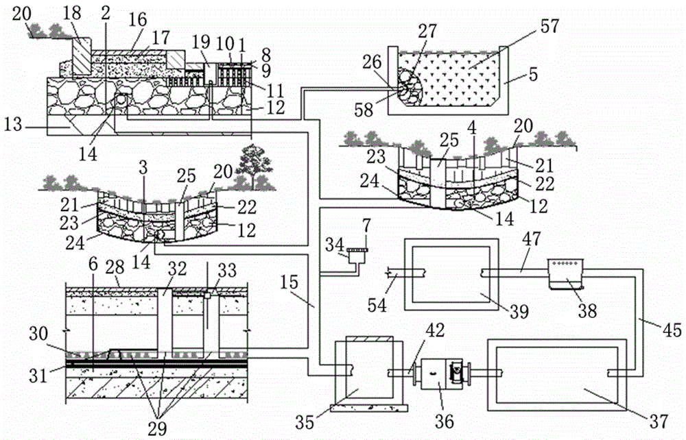
图1为本实用新型系统的结构示意图。FIG. 1 is a schematic structural diagram of the system of the present invention.
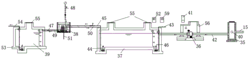
图2为本实用新型系统中雨水收集结构的平面布置图。FIG. 2 is a plan view of the rainwater collection structure in the system of the present invention.
图3为本实用新型系统中雨水收集结构的工艺流程图。3 is a process flow diagram of the rainwater collection structure in the system of the present invention.
图中:1-道路层结构、2-人行道结构、3-绿化结构、4-下凹式绿地结构、5-花池及树池结构、6-铺装面结构、7-屋面、8-透水沥青混凝土层、9-防水封层、10-中粒式沥青混凝土层、11-水泥稳定碎石基层、12-天然级配碎石层、13-素土夯实层、14-导流管、15-雨水排水管、16-透水路面砖层、17-干性水泥砂浆层、18-路缘石、19-雨水收集井、20-植被层、21-种植土层、22-粗砂层、23-过滤土工布层、24-防渗土工布层、25-环保溢流口、26-第一溢流管、27-鹅卵石、28-透水铺装面层、29- 雨水收集系统、30-高分子排水异型片、31-虹吸排水槽、32-观察井、33-集水井、34-屋面雨水管、35-安全分流井、36-弃流控制器、37-玻璃钢蓄水池、38-地埋一体机、39-玻璃钢清水池、40-第二溢流管、41-弃流控制柜、42-进水管、43-市政排污管、44-提升泵、45-雨水提升进管、46-排污泵、47-雨水提升出管、48-自来水补水进管、49-自来水补水出管、50-泄压回水管、51-设备排污管、52-雨水控制柜、53-供水变频泵、54-雨水回用管、55-上人孔、56-弃流控制器检查井、57-花池树池土、58-过滤网、59-变频控制柜。In the picture: 1- Road layer structure, 2- Sidewalk structure, 3- Green structure, 4- Sunken green space structure, 5- Flower pond and tree pond structure, 6- Pavement structure, 7- Roof, 8- Permeable asphalt Concrete layer, 9-Waterproof sealing layer, 10-Medium-grain asphalt concrete layer, 11-Cement stabilized gravel base, 12-Natural graded gravel layer, 13-Plain soil compaction layer, 14-Drain pipe, 15- Rainwater drainage pipe, 16-permeable pavement brick layer, 17-dry cement mortar layer, 18-curbstone, 19-rainwater collection well, 20-vegetation layer, 21-planting soil layer, 22-coarse sand layer, 23-filtration Geotextile layer, 24-impermeable geotextile layer, 25-environmental overflow, 26-first overflow pipe, 27-pebble, 28-permeable pavement surface, 29-rainwater collection system, 30-polymer drainage Special-shaped sheet, 31-siphon drainage groove, 32-observation well, 33-water collection well, 34-roof rainwater pipe, 35-safety diversion well, 36-abandoned flow controller, 37-glass fiber reinforced plastics reservoir, 38-ground integrated machine , 39-glass fiber reinforced plastic clear water tank, 40-second overflow pipe, 41-abandoned flow control cabinet, 42-water inlet pipe, 43-municipal sewage pipe, 44-lift pump, 45-rainwater lifting inlet pipe, 46-sewage pump, 47-Rainwater lift out pipe, 48-Tap water supply water inlet pipe, 49-Tap water supply water outlet pipe, 50-Pressure relief return pipe, 51-Equipment sewage pipe, 52-Rainwater control cabinet, 53-Water supply frequency conversion pump, 54-Rainwater return pipe Use pipe, 55-upper manhole, 56-abandoned flow controller inspection well, 57-flower pond tree pond soil, 58-filter screen, 59-frequency conversion control cabinet.
具体实施方式Detailed ways
为了使本领域技术人员更好的理解本实用新型,以下结合参考附图并结合实施例对本实用新型作进一步清楚、完整的说明。需要说明的是,在不冲突的情况下,本申请中的实施例及实施例中的特征可以相互组合。In order to make those skilled in the art better understand the present utility model, the present utility model will be further clearly and completely described below with reference to the accompanying drawings and the embodiments. It should be noted that the embodiments in the present application and the features of the embodiments may be combined with each other in the case of no conflict.
如图1至图3所示,一种海绵城市排渗水结构及雨水收集利用系统,包括排渗水结构和雨水收集结构。As shown in Figures 1 to 3, a sponge city drainage structure and a rainwater collection and utilization system, including a drainage structure and a rainwater collection structure.
排渗水结构包括道路层结构1、人行道结构2、绿化结构3、下凹式绿地结构4、花池及树池结构5、铺装面结构6和屋面7。The drainage structure includes road layer structure 1 ,
道路层结构1由上到下依次包括透水沥青混凝土层8、防水封层9、中粒式沥青混凝土层10、水泥稳定碎石基层11、天然级配碎石层12、素土夯实层13;天然级配碎石层12以级配碎石作为骨料,碎石的最大粒径不大于40mm,天然级配碎石层12内放置有导流管14,导流管14的管径不大于100mm,导流管14侧壁开有通孔,导流管14的侧壁包有土工布,导流管14与雨水排水管15连通,导流管14周围的碎石块无法通过土工布进入管内,这样能避免碎石块堵塞通孔,影响雨水收集;透水沥青混凝土层8的渗透率高,雨水容易渗透到天然级配碎石层12中,再进过导流管14流入雨水排水管15。The road layer structure 1 includes, from top to bottom, a permeable asphalt concrete layer 8, a
人行道结构2由上到下依次包括透水路面砖层16、干性水泥砂浆层17、天然级配碎石层12和素土夯实层13;天然级配碎石层12以级配碎石作为骨料,碎石的最大粒径不大于40mm,天然级配碎石层12内放置有导流管14,导流管14的管径不大于100mm,导流管14侧壁开有通孔,导流管14的侧壁包有土工布,导流管14与雨水排水管15连通;道路层结构1与人行道结构2之间设有路缘石18,采用透水混凝土座立路缘石18;道路两侧隔一定距离设置雨水收集井19及开口路缘石18,雨水收集井19通过雨水收集管道与道路层结构1、人行道结构2的天然级配碎石层12中的导流管14相互连通。The
绿化结构3和下凹式绿地结构4的构造相同,其由上到下依次包括植被层20、种植土层21、粗砂层22、过滤土工布层23、天然级配碎石层12、防渗土工布层24、素土夯实层13;天然级配碎石层12以级配碎石作为骨料,碎石的最大粒径不大于40mm,天然级配碎石层12内放置有导流管14,导流管14的管径不大于100mm,导流管14侧壁开有通孔,导流管14的侧壁包有土工布,导流管14与雨水排水管15连通;绿化结构3和下凹式绿地结构4均设置有环保溢流口25,环保溢流口25与导流管14及雨水排水管15相互连通;当绿化结构3和下凹式绿地结构4内的积水过多时,雨水从环保溢流口25进入导流管14排走,减少因积水过多使细菌大量繁殖令植物根部受到细菌的感染而导致腐根的情况。The green structure 3 and the concave green space structure 4 have the same structure, which sequentially includes a vegetation layer 20, a planting soil layer 21, a coarse sand layer 22, a filter geotextile layer 23, a natural graded gravel layer 12, a The infiltration geotextile layer 24, the plain soil compaction layer 13; the natural graded crushed stone layer 12 uses graded crushed stone as aggregate, the maximum particle size of the crushed stone is not more than 40mm, and a diversion is placed in the natural graded crushed stone layer 12 Pipe 14, the diameter of the guide pipe 14 is not more than 100mm, the side wall of the guide pipe 14 is provided with a through hole, the side wall of the guide pipe 14 is covered with geotextile, and the guide pipe 14 is communicated with the rainwater drainage pipe 15; greening structure 3 and the concave green space structure 4 are both provided with an environmental protection overflow port 25, and the environmental protection overflow port 25 is communicated with the guide pipe 14 and the rainwater drainage pipe 15; When there is too much rainwater, the rainwater enters the diversion pipe 14 from the environmental protection overflow port 25 and is drained away, so as to reduce the situation that the roots of the plants are infected by bacteria due to the excessive accumulation of water, which causes the root rot.
花池及树池结构5采用钢筋混凝土结构,钢筋混凝土结构内填设有花池树池土57,在距底600mm的位置设置第一溢流管26,第一溢流管26外包过滤网58,且在其周边铺设200mm的鹅卵石27,第一溢流管26与雨水排水管15连通。The flower pond and the tree pond structure 5 adopt a reinforced concrete structure, the reinforced concrete structure is filled with flower pond
铺装面结构6由上到下依次包括透水铺装面层28、干性水泥砂浆层17、天然级配碎石层12、雨水收集系统29;雨水收集系统29优选PDS雨水收集系统,其由高分子排水异型片30、虹吸排水槽31、观察井32、集水井33组成,高分子排水异型片30上铺设过滤土工布层23,并按一定间距布设虹吸排水槽31,观察井32、集水井33及雨水排水管15依次连通。The pavement surface structure 6 includes, from top to bottom, a permeable
屋面7上设置有屋面雨水管34,屋面雨水管34与雨水排水管15连通。The
雨水收集结构包括安全分流井35、弃流控制器36、玻璃钢蓄水池37、地埋一体机38、玻璃钢清水池39。The rainwater collection structure includes a safety diversion well 35 , an abandoned
雨水排水管15的终端与安全分流井35连接,安全分流井35的侧壁上设置有第二溢流管40,当降雨量大时,雨水可从第二溢流管40排入与市政污水管连通的管道;安全分流井35通过进水管42与玻璃钢蓄水池37连通,弃流控制器36设置在进水管42上,弃流控制器36由弃流控制柜41控制;进入玻璃钢蓄水池37的雨水须经过弃流控制器36进行截污、弃流、过滤,通过采集的降雨量多模参数,精确控制雨水弃流量和雨水收集量,有效减少雨水杂质流入,降低后续处理装置负荷;玻璃钢蓄水池37的顶部设置有两个上人孔55,便于对玻璃钢蓄水池37内进行清理作业;弃流雨水流入下游雨水管道,弃流后洁净雨水流入玻璃钢蓄水池37,余量雨水溢流至下游管段;玻璃钢蓄水池37内的入口处下端设有泵坑,泵坑内放置有排污泵46,排污泵46一端与市政排污管43连通,玻璃钢蓄水池37内的出口处下端设有泵坑,泵坑内放置有提升泵44,提升泵44一端连接有雨水提升进管45,雨水提升进管45的另一端与地埋一体机38连通,地埋一体机38的另一端连接有雨水提升出管47,雨水提升出管47的另一端与玻璃钢清水池39连通;地埋一体机38上还连接有自来水补水进管48、自来水补水出管49、泄压回水管50和设备排污管51,自来水补水出管49的另一端与玻璃钢清水池39连通,泄压回水管50的另一端与玻璃钢蓄水池37连接,自来水补水进管48上设置有倒流防止器,以防污染自来水;雨水经地埋一体机38处理后直接提升至玻璃钢清水池39,不足时采用自来水补给;玻璃钢清水池39的顶部设置有一个上人孔55,便于对玻璃钢清水池39内进行清理作业;玻璃钢清水池39内设置有供水变频泵53,供水变频泵53一端连接雨水回用管54,采用供水变频泵53通过雨水回用管54输出至各用水点;玻璃钢清水池39内还设置有排污泵46,排污泵46一端与市政排污管43连通。The terminal of the
上述海绵城市排渗水结构及雨水收集利用系统的使用方法如下:The usage methods of the above-mentioned sponge city drainage structure and rainwater collection and utilization system are as follows:
步骤一:部分雨水从道路层结构1、人行道结构2、绿化结构3、下凹式绿地结构4、花池及树池结构5、铺装面结构6渗透下来,通过导流管14排入雨水排水管15;Step 1: Part of the rainwater penetrates from the road layer structure 1, the
步骤二:部分雨水通过雨水收集井19、环保溢流口25排入雨水排水管15,经雨水排水管15再排至安全分流井35;Step 2: Part of the rainwater is discharged into the
步骤三:通过安全分流井35对雨水进行分流,一部分雨水通过弃流控制器36并经进水管42进入玻璃钢蓄水池37,一部分雨水通过第二溢流管40进入到与市政排污管43连接的管道内排走;弃流控制器检查井56顶部设置检查口,采用弃流控制柜41进行智能控制;Step 3: The rainwater is diverted through the safety diversion well 35, a part of the rainwater enters the
步骤四:玻璃钢蓄水池37入口端下方设置排污泵46,排污泵46与市政排污管43连通,出口端下方设置提升泵44,提升泵44与雨水提升进管45连接,雨水提升进管45与地埋一体机38连通,在地面设置雨水控制柜52、变频控制柜59对雨水进行监控供水、排水、补水等情况;地埋一体机38通过雨水提升出管47与玻璃钢清水池39连通;雨水经地埋一体机38过滤后,引入玻璃钢清水池39储存备用,玻璃钢清水池39中水通过雨水回用管54用于绿化、消防、其他用水。Step 4: A
实施例仅仅是本实用新型一部分实施例,而不是全部的实施例。基于本实用新型中的实施例,本领域普通技术人员在没有作出创造性劳动前提下所获得的所有其它实施例,都属于本实用新型保护的范围。The embodiments are only some of the embodiments of the present invention, but not all of the embodiments. Based on the embodiments of the present invention, all other embodiments obtained by those of ordinary skill in the art without creative work fall within the protection scope of the present invention.
Claims (5)
Priority Applications (1)
| Application Number | Priority Date | Filing Date | Title |
|---|---|---|---|
| CN202020314819.6U CN211922820U (en) | 2020-03-14 | 2020-03-14 | Drainage and seepage structure and rainwater collection and utilization system of sponge city |
Applications Claiming Priority (1)
| Application Number | Priority Date | Filing Date | Title |
|---|---|---|---|
| CN202020314819.6U CN211922820U (en) | 2020-03-14 | 2020-03-14 | Drainage and seepage structure and rainwater collection and utilization system of sponge city |
Publications (1)
| Publication Number | Publication Date |
|---|---|
| CN211922820U true CN211922820U (en) | 2020-11-13 |
Family
ID=73347394
Family Applications (1)
| Application Number | Title | Priority Date | Filing Date |
|---|---|---|---|
| CN202020314819.6U Expired - Fee Related CN211922820U (en) | 2020-03-14 | 2020-03-14 | Drainage and seepage structure and rainwater collection and utilization system of sponge city |
Country Status (1)
| Country | Link |
|---|---|
| CN (1) | CN211922820U (en) |
Cited By (2)
| Publication number | Priority date | Publication date | Assignee | Title |
|---|---|---|---|---|
| CN111255011A (en) * | 2020-03-14 | 2020-06-09 | 山西四建集团有限公司 | Sponge urban drainage and seepage structure, rainwater collection and utilization system and working method thereof |
| CN120683928A (en) * | 2025-07-18 | 2025-09-23 | 中铁二十五局集团第二工程有限公司 | A sponge city drainage circulation system and construction method thereof |
-
2020
- 2020-03-14 CN CN202020314819.6U patent/CN211922820U/en not_active Expired - Fee Related
Cited By (2)
| Publication number | Priority date | Publication date | Assignee | Title |
|---|---|---|---|---|
| CN111255011A (en) * | 2020-03-14 | 2020-06-09 | 山西四建集团有限公司 | Sponge urban drainage and seepage structure, rainwater collection and utilization system and working method thereof |
| CN120683928A (en) * | 2025-07-18 | 2025-09-23 | 中铁二十五局集团第二工程有限公司 | A sponge city drainage circulation system and construction method thereof |
Similar Documents
| Publication | Publication Date | Title |
|---|---|---|
| CN111255011A (en) | Sponge urban drainage and seepage structure, rainwater collection and utilization system and working method thereof | |
| CN104480994B (en) | A kind of square, urban green space rainwater-collecting reutilization system | |
| CN202374807U (en) | Solar rainwater irrigation device for green belts | |
| CN105089302B (en) | A kind of Rain Garden system for the shunting of community's rainwater, peak clipping and ecological purification | |
| CN106193259B (en) | A rainwater collection and utilization system and construction method for sponge city | |
| CN106400648B (en) | Sponge City Water Collection and Purification Ecological Road | |
| CN209686564U (en) | A kind of small sponge urban ecology rainwater storage cell system | |
| CN104196277A (en) | Functional rainwater garden suitable for interior of urban community grassy area in Shanghai | |
| CN105133692B (en) | A landscape-type ecological roof rainwater source combined pollution reduction and waterlogging prevention system | |
| CN211112989U (en) | Intelligent water collecting and draining system applied to sponge city | |
| CN201972229U (en) | Residential rainwater comprehensive utilization system device | |
| CN206844282U (en) | The collection and purification of town road rainfall runoff utilize system | |
| CN207032427U (en) | A kind of Rainwater collection system suitable for old cell | |
| CN108625453A (en) | Skyscraper sponge City complex system | |
| CN201284492Y (en) | Simple and practical overhead road rainwater utilization system | |
| CN201817851U (en) | Rainwater ecological utilization system | |
| CN111285503A (en) | Outdoor courtyard rainwater resource recycling integrated system and rainwater purification method | |
| CN207633496U (en) | Integrated rainwater recycling system for sponge cities in super-large square | |
| CN106245736A (en) | A kind of double water source tree pond rainwater utilization system | |
| CN206545257U (en) | A kind of novel greening band water storage structure | |
| CN110016849B (en) | Full-penetration asphalt pavement system capable of effectively controlling pavement rainwater runoff pollution | |
| CN111501948A (en) | Rainwater collecting and processing system for roof of residential building | |
| CN207469030U (en) | A kind of urban road filtration, purification and collection drainage systems | |
| CN206793216U (en) | A kind of urban road rainwater-collecting, the shunting for conserving vegetation are regulated and stored system | |
| CN211999203U (en) | A kind of natural purification rainwater recycling treatment and utilization system |
Legal Events
| Date | Code | Title | Description |
|---|---|---|---|
| GR01 | Patent grant | ||
| GR01 | Patent grant | ||
| CF01 | Termination of patent right due to non-payment of annual fee |
Granted publication date: 20201113 |
|
| CF01 | Termination of patent right due to non-payment of annual fee |