CN211902639U - LED street lamp with high heat dissipation performance - Google Patents
LED street lamp with high heat dissipation performance Download PDFInfo
- Publication number
- CN211902639U CN211902639U CN202020925727.1U CN202020925727U CN211902639U CN 211902639 U CN211902639 U CN 211902639U CN 202020925727 U CN202020925727 U CN 202020925727U CN 211902639 U CN211902639 U CN 211902639U
- Authority
- CN
- China
- Prior art keywords
- heat dissipation
- lamp
- groove
- head
- fins
- Prior art date
- Legal status (The legal status is an assumption and is not a legal conclusion. Google has not performed a legal analysis and makes no representation as to the accuracy of the status listed.)
- Expired - Fee Related
Links
Images


Landscapes
- Arrangement Of Elements, Cooling, Sealing, Or The Like Of Lighting Devices (AREA)
Abstract
The utility model discloses an LED street lamp with high heat dissipation performance, which comprises a long strip-shaped mounting plate, the top surface of the mounting plate is provided with a heat dissipation groove which is arranged coaxially with the mounting plate, a radiator is arranged in the radiating groove, the section of the radiator is arranged in a T shape, a radiating head is formed at the top of the radiator, a plurality of radiating fins are arranged on the radiating head, a gap is formed between every two adjacent radiating fins, a power supply device is fixed on the heat dissipation head, a support plate is connected below the heat dissipation head, the bottom of the support plate passes through the heat dissipation groove and then extends downwards, a lamp housing is fixed at the bottom of the supporting plate, an LED lamp is fixed in the lamp housing, short fins for heat dissipation are formed on the top surface of the lamp housing, and the length of the short fins is smaller than that of the heat dissipation fins; a connection groove is formed at an end of the mounting plate, and a slider is slidably connected to the connection groove.
Description
Technical Field
The utility model relates to a LED street lamp technical field especially relates to a LED street lamp with high heat dispersion.
Background
An LED, also called a light emitting diode, is a solid state semiconductor device that can convert electrical energy into visible light, and can directly convert electricity into light.
The LED lamp has the advantages of small volume and high luminous efficiency, but light rays emitted by the LED lamp have strong directivity, the directivity is caused by the special structure of the LED lamp, namely the LED lamp is provided with a semiconductor substrate, so that the LED lamp can not emit light from two sides, generally only can emit light in one direction, and a plurality of high-power LEDs are assembled with a lens, so that the LED lamp can only emit light forwards, the angle is limited, the structure limits can not illuminate all sides when the LED lamp emits light, and light rays at one corner can not reach all the time, namely the directivity of the LED light source. The light emission angle of the LED is about 120 degrees. The illumination angle of the energy-saving lamp can be almost all-sided, and the illumination angle can be approximately considered to be 360 degrees.
Therefore, the lighting brightness and the lighting range of a single LED lamp are smaller than those of an energy-saving lamp with the same power due to the lighting directivity, and in order to improve the lighting brightness and the lighting range, a plurality of LED lamps are arranged to form an LED lamp array so as to enhance the lighting brightness and enlarge the lighting range.
SUMMERY OF THE UTILITY MODEL
The utility model aims to solve the technical problem that to above-mentioned technical current situation and provide a LED street lamp with high heat dispersion.
In order to achieve the above purpose, the utility model provides a following technical scheme:
an LED street lamp with high heat dissipation performance comprises an elongated mounting plate, a heat dissipation groove is formed in the top surface of the mounting plate, the heat dissipation groove and the mounting plate are arranged in the same axial direction, a radiator is arranged in the heat dissipation groove, the cross section of the radiator is arranged in a T shape, a heat dissipation head is formed at the top of the radiator, a plurality of heat dissipation fins are arranged on the heat dissipation head, the heat dissipation fins are symmetrically arranged on two sides of the heat dissipation head, each heat dissipation fin is vertically connected to the heat dissipation head, a gap is formed between every two adjacent heat dissipation fins, a power supply device is fixed on the heat dissipation head, a support plate is connected below the heat dissipation head, the bottom of the support plate penetrates through the heat dissipation groove and then extends downwards, a lamp housing is fixed at the bottom of the support plate, and an LED lamp is fixed in the lamp housing, short fins for heat dissipation are formed on the top surface of the lamp shell, and the length of the short fins is smaller than that of the heat dissipation fins; a connection groove is formed at an end of the mounting plate, and a slider is slidably connected to the connection groove. Through the structure, the heat dissipation area of the heat radiator can be obviously increased, and the heat dissipation efficiency is improved.
As the utility model discloses an improvement, power supply unit is including power installation panel and power support the bottom of power installation panel is formed with first recess be formed with the second recess on the power support, power installation panel with the power support each other lock together and pass through bolt fastening, the notch of first recess with the notch of second recess is just right, works as the power installation panel with behind the power support lock, first recess with the second recess has formed an inclosed installation cavity, the radiating head is located in the installation cavity. Through this kind of structure on the one hand can fix the radiator and carry on spacingly to the radiating head, on the other hand can utilize the electric conduction of contact to further promote the radiating efficiency, enlarges heat radiating area, can also dispel the heat to the power simultaneously.
As the utility model discloses a preferred, be formed with the light trough in the lamp body, the notch of light trough is seted up on the bottom surface of lamp body set up the location spout has been seted up on the relative two-sided cell wall of light trough, the both ends difference sliding connection of LED lamps and lanterns is in the location spout. The structure is favorable for the installation and the disassembly of the LED lamp, the LED lamp belongs to a quick-wear part under the condition of high luminous intensity, and the LED lamp is convenient to replace through a sliding installation mode.
As a specific technical scheme of the utility model two locating holes have been seted up to the tank bottom of spread groove, two locating holes be located same height wear to be equipped with the locating pin in the locating hole the guide way has been seted up on the slider, the tip of locating pin is worn to establish in the guide way. The setting of slider can be done the axial position adjustment of limited range to whole LED lamp on the one hand, and on the other hand can carry on supplementary heat dissipation mechanisms such as miniature fan on the slider and promote air circulation, promotes the radiating efficiency
Compared with the prior art, the utility model has the advantages of: the heat dissipation structure is arranged in the LED lamp and consists of a heat dissipation head, a support plate and short fins for heat dissipation on the lamp shell, an air convection space is formed between the short fins for heat dissipation and the mounting plate, the first air convection heat dissipation can be directly carried out above the lamp shell after the lamp is heated, then the rest part of heat is upwards conducted through the support plate made of metal, in the process of conduction, part of heat is continuously subjected to heat exchange with air for heat dissipation, part of heat transferred to the top of the support plate is dissipated through the heat dissipation head, in order to improve the heat dissipation efficiency, the heat dissipation head is provided with a plurality of heat dissipation fins, the heat dissipation fins increase the contact area between the heat dissipation head and the air, meanwhile, a power supply is fixed on the heat dissipation head, a hollow mounting cavity is formed at the bottom of the power supply, the heat dissipation head is positioned in the mounting cavity, and the end parts of the heat dissipation fins are in contact with, according to the structure, on one hand, a second air convection space is formed in the mounting cavity, secondary air convection heat dissipation of heat can be performed in the mounting cavity, meanwhile, heat generated by the power supply can be transferred to the heat dissipation head for heat dissipation, the LED lamp and the power supply of the LED lamp can be simultaneously dissipated by using the same heat dissipation device, and the LED lamp and the power supply of the LED lamp have high heat dissipation efficiency.
Drawings
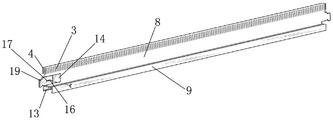
Fig. 1 is a schematic overall structure diagram of an LED street lamp with high heat dissipation performance in an embodiment of the present invention;
FIG. 2 is a partially enlarged structural view of FIG. 1;
FIG. 3 is a side view of FIG. 1;
fig. 4 is an assembly view of the power supply device of fig. 3 after assembly.
Detailed Description
The present invention will be described in further detail with reference to the following embodiments.
As shown in the accompanying drawings, the present embodiment is an LED street lamp with high heat dissipation performance, which includes a long strip-shaped mounting plate 1, a heat sink 2 has been opened on the top surface of the mounting plate, the heat sink and the mounting plate are arranged in the same axial direction, a heat sink is arranged in the heat sink, the cross section of the heat sink is in a T-shape, a heat sink 3 is formed on the top of the heat sink, a plurality of heat dissipation fins 4 are arranged on the heat sink, the heat dissipation fins are symmetrically arranged on two sides of the heat sink, and each heat dissipation fin is vertically connected to the heat sink.
Be formed with the clearance between two adjacent heat radiation fins the last power supply unit that is fixed of radiator, power supply unit is including power installation panel 5 and power support 6, is fixing power 18 on power installation panel, is formed with first recess 51 in the bottom of power installation panel be formed with second recess 61 on the power support, power installation panel and power support can be each other the lock and be in the same place and fixed through bolt 7, the notch of first recess is just right each other with the notch of second recess, and the groove width of first recess equals with the groove width of second recess, after power installation panel and power support lock, first recess with the second recess forms a inclosed installation cavity, and aforementioned radiator just is arranged in this installation cavity.
A support plate 8 is connected below the heat dissipation head, the bottom of the support plate passes through the heat dissipation groove and then extends downwards, a lamp shell 9 is fixed at the bottom of the support plate, the lamp shell is square, on one hand, the processing and the assembly of the reflector 20 are convenient, on the other hand, the contact area with air can be enlarged, an LED lamp 10 is fixed in the lamp shell, a short fin 11 for heat dissipation is formed on the top surface of the lamp shell, the length of the short fin is smaller than that of the heat dissipation fin, two long fins 12 are formed on two edges of the top surface of the lamp shell, the length of the long fin is larger than that of the short fin but smaller than that of the heat dissipation fin, the long fin can be supported on the bottom surface of the mounting plate, so that a space is formed between the short fin and the bottom surface of the mounting plate, namely, an air convection space is formed between the short fin and the mounting plate, and the first air convection heat dissipation can, the remaining part of the heat is then conducted upwards through the metal support plate. The LED lamp generates heat after the light is emitted, the heat is transferred to the lamp shell and is radiated upwards, so that the temperature rise of a space between the short fins and the bottom surface of the mounting plate is increased, the air pressure is increased, hot air can flow outwards along the heat dissipation grooves due to the arrangement of the heat dissipation grooves on the mounting plate, and meanwhile, external air can be circularly supplemented into the space for heat dissipation and cooling.
Part of the rest heat is upwards transferred along the metal support plate, the plate body of the metal support plate is longer, and in the process that the heat is transferred to the heat dissipation head positioned at the top of the metal support plate, part of the heat is subjected to heat exchange with air on the plate body, and the heat transferred to the heat dissipation head is dissipated through the heat dissipation fins. The heat dissipation fins can dissipate heat generated by the power supply besides dissipating heat transferred upwards by the lamp housing.
The lamp body is internally provided with the lamp groove, the notch of the lamp groove is arranged on the bottom surface of the lamp body, the two opposite groove walls of the lamp groove are provided with the positioning sliding grooves 13, and two ends of the LED lamp 10 are respectively connected in the positioning sliding grooves in a sliding manner.
In addition, a coupling groove 14, in which a slider 19 is slidably coupled, is formed at an end of the mounting plate. Two positioning holes are formed in the bottom of the connecting groove, the two positioning holes are located at the same height, a positioning pin 16 penetrates through the positioning holes, a guide groove 17 is formed in the sliding block, and the end portion of the positioning pin penetrates through the guide groove. The setting of this kind of slider makes can carry out the axial position adjustment of limited range to the mounting panel through the slider that slides, in addition, gives the slider through the setting, can fix a miniature fan or other external heat abstractor on the slider, further accelerates air circulation speed, promotes the radiating efficiency.
The assembly process of the LED street lamp in the embodiment is as follows: the method comprises the steps of firstly manufacturing a mounting plate by utilizing a stamping forming process and a metal cutting process, manufacturing a lamp shell, a power supply mounting panel, a power supply support and a support plate, then welding the support plate on the top surface of the lamp shell by argon arc welding, and because a radiating fin only plays a radiating role, the support plate can be fixed on two sides of a radiating head in a bonding mode, then buckling the power supply mounting panel and the power supply support together in a welding or clamping mode, then fixing a reflector 20 on the lamp shell, forming a lamp groove at the bottom of the lamp shell, then putting an LED lamp into the lamp groove from the side, then sliding the LED lamp to a specified position along a positioning sliding groove for positioning and fixing, and then sequentially putting other LED lamps until all the LED lamps are assembled. And finally, covering the side surface of the lamp groove by using a cover plate, and hoisting the whole LED lamp to the specified position at the top of the street lamp pole for installation, thereby completing the whole installation process.
It is above only the utility model discloses a preferred embodiment, the utility model discloses a scope of protection does not only confine above-mentioned embodiment, the all belongs to the utility model discloses a technical scheme under the thinking all belongs to the utility model discloses a scope of protection. It should be noted that, for those skilled in the art, various modifications and decorations can be made without departing from the principle of the present invention, and these modifications and decorations should also be regarded as the protection scope of the present invention.
Claims (4)
1. The utility model provides a LED street lamp with high heat dissipating ability which characterized in that: the LED lamp comprises a long strip-shaped mounting plate, wherein a heat dissipation groove is formed in the top surface of the mounting plate, the heat dissipation groove and the mounting plate are coaxially arranged, a radiator is arranged in the heat dissipation groove, the cross section of the radiator is arranged in a T shape, a heat dissipation head is formed at the top of the radiator, a plurality of heat dissipation fins are arranged on the heat dissipation head, the heat dissipation fins are symmetrically arranged on two sides of the heat dissipation head, each heat dissipation fin is vertically connected to the heat dissipation head, a gap is formed between every two adjacent heat dissipation fins, a power supply device is fixed to the heat dissipation head, a support plate is connected below the heat dissipation head, the bottom of the support plate penetrates through the heat dissipation groove and then extends downwards, a lamp housing is fixed to the bottom of the support plate, an LED lamp is fixed to the lamp housing, and short fins for heat dissipation are formed on the top surface of the lamp housing, the length of the short fins is smaller than that of the heat dissipation fins; a connection groove is formed at an end of the mounting plate, and a slider is slidably connected to the connection groove.
2. The LED street lamp with high heat dissipation performance as set forth in claim 1, wherein: power supply unit is including power installation panel and power support the bottom of power installation panel is formed with first recess be formed with the second recess on the power support, the power installation panel with the power support each other the lock be in the same place and through the bolt fastening, the notch of first recess with the notch of second recess is just right, works as the power installation panel with behind the power support lock, first recess with the second recess has formed an inclosed installation cavity, the radiator head is located in the installation cavity.
3. The LED street lamp with high heat dissipation performance as set forth in claim 1, wherein: the LED lamp comprises a lamp housing, a lamp groove is formed in the lamp housing, a notch of the lamp groove is formed in the bottom surface of the lamp housing, positioning sliding grooves are formed in two opposite groove walls of the lamp groove, and two ends of the LED lamp are connected in the positioning sliding grooves in a sliding mode.
4. The LED street lamp with high heat dissipation performance as set forth in claim 1, wherein: two positioning holes are formed in the bottom of the connecting groove, the two positioning holes are located at the same height, positioning pins penetrate through the positioning holes, guide grooves are formed in the sliding block, and the end portions of the positioning pins penetrate through the guide grooves.
Priority Applications (1)
| Application Number | Priority Date | Filing Date | Title |
|---|---|---|---|
| CN202020925727.1U CN211902639U (en) | 2020-05-28 | 2020-05-28 | LED street lamp with high heat dissipation performance |
Applications Claiming Priority (1)
| Application Number | Priority Date | Filing Date | Title |
|---|---|---|---|
| CN202020925727.1U CN211902639U (en) | 2020-05-28 | 2020-05-28 | LED street lamp with high heat dissipation performance |
Publications (1)
| Publication Number | Publication Date |
|---|---|
| CN211902639U true CN211902639U (en) | 2020-11-10 |
Family
ID=73270334
Family Applications (1)
| Application Number | Title | Priority Date | Filing Date |
|---|---|---|---|
| CN202020925727.1U Expired - Fee Related CN211902639U (en) | 2020-05-28 | 2020-05-28 | LED street lamp with high heat dissipation performance |
Country Status (1)
| Country | Link |
|---|---|
| CN (1) | CN211902639U (en) |
-
2020
- 2020-05-28 CN CN202020925727.1U patent/CN211902639U/en not_active Expired - Fee Related
Similar Documents
| Publication | Publication Date | Title |
|---|---|---|
| CN101900271A (en) | Light-emitting diode lamps with better heat dissipation effect | |
| KR101034482B1 (en) | Luminaire | |
| CN101576241B (en) | Heat dissipation method of LED radiator and radiator implementing the method | |
| KR100966599B1 (en) | Led lighting lamp | |
| KR101231658B1 (en) | LED lamp provided an improved capability of discharging heat | |
| CN101576242B (en) | Heat dissipation method of high-power LED radiator and radiator implementing the method | |
| CN203656762U (en) | Rear fog lamp used for automobile | |
| CN102889524B (en) | Honeycomb-convection heat-superconducting LED (light emitting diode) reflector lamp | |
| CN219177539U (en) | Automobile LED headlight with good heat dissipation effect | |
| KR200466198Y1 (en) | A radial shape type radiate heat | |
| KR101039556B1 (en) | Socket type LED lighting device having double cooling fin structure | |
| US11022294B2 (en) | Lighting module and a luminaire comprising the lighting modulespe | |
| CN102287644A (en) | High-power light-emitting diode (LED) lamp with double radiating mechanisms of heat conduction and convectional radiating | |
| CN223076880U (en) | LED shot-light convenient to heat dissipation | |
| CN220870681U (en) | High heat dissipation automobile LED headlight | |
| CN222164551U (en) | Energy-saving industrial and mining lamp with good heat dissipation effect | |
| CN218001348U (en) | Car lamp capable of efficiently dissipating heat and condensing light | |
| CN220119336U (en) | LED industrial and mining lamp | |
| CN211952697U (en) | Radiator for lamp | |
| CN220323690U (en) | Light source structure of photographic lamp | |
| CN221375615U (en) | Heat radiation structure of stage lamp module | |
| CN216976752U (en) | Waterproof LED projection lamp, LED water wave lamp, laser lamp machine case and radiator integrated heat radiation structure | |
| CN202546466U (en) | Novel rapid heat radiation integral LED industrial and mining lamp | |
| CN221402953U (en) | Single-ended LED light-emitting device | |
| CN223105880U (en) | High heat dissipation headlights |
Legal Events
| Date | Code | Title | Description |
|---|---|---|---|
| GR01 | Patent grant | ||
| GR01 | Patent grant | ||
| CF01 | Termination of patent right due to non-payment of annual fee |
Granted publication date: 20201110 |