CN211875322U - An extrusion-resistant multi-layer composite pipe - Google Patents
An extrusion-resistant multi-layer composite pipe Download PDFInfo
- Publication number
- CN211875322U CN211875322U CN202020370750.9U CN202020370750U CN211875322U CN 211875322 U CN211875322 U CN 211875322U CN 202020370750 U CN202020370750 U CN 202020370750U CN 211875322 U CN211875322 U CN 211875322U
- Authority
- CN
- China
- Prior art keywords
- pipe
- pvc outer
- puigging
- heat preservation
- outside
- Prior art date
- Legal status (The legal status is an assumption and is not a legal conclusion. Google has not performed a legal analysis and makes no representation as to the accuracy of the status listed.)
- Expired - Fee Related
Links
- 239000002131 composite material Substances 0.000 title claims abstract description 17
- 238000001125 extrusion Methods 0.000 title claims abstract description 10
- 239000004698 Polyethylene Substances 0.000 claims abstract description 25
- -1 polyethylene Polymers 0.000 claims abstract description 25
- 229920000573 polyethylene Polymers 0.000 claims abstract description 25
- 229910000831 Steel Inorganic materials 0.000 claims abstract description 19
- 239000011490 mineral wool Substances 0.000 claims abstract description 19
- 239000010959 steel Substances 0.000 claims abstract description 19
- 238000004321 preservation Methods 0.000 claims abstract description 11
- 239000011435 rock Substances 0.000 claims abstract 4
- 239000004831 Hot glue Substances 0.000 claims description 6
- 229920000742 Cotton Polymers 0.000 claims 2
- 238000004026 adhesive bonding Methods 0.000 claims 2
- 150000001875 compounds Chemical class 0.000 claims 1
- 230000000694 effects Effects 0.000 abstract description 3
- 230000001681 protective effect Effects 0.000 abstract 1
- 238000009413 insulation Methods 0.000 description 34
- 238000007789 sealing Methods 0.000 description 4
- 238000010586 diagram Methods 0.000 description 3
- 239000012530 fluid Substances 0.000 description 3
- 239000007789 gas Substances 0.000 description 2
- 238000009434 installation Methods 0.000 description 2
- VNWKTOKETHGBQD-UHFFFAOYSA-N methane Chemical compound C VNWKTOKETHGBQD-UHFFFAOYSA-N 0.000 description 2
- 238000000034 method Methods 0.000 description 2
- 238000012986 modification Methods 0.000 description 2
- 230000004048 modification Effects 0.000 description 2
- 230000009286 beneficial effect Effects 0.000 description 1
- 238000005336 cracking Methods 0.000 description 1
- 238000007710 freezing Methods 0.000 description 1
- 230000005484 gravity Effects 0.000 description 1
- 238000010438 heat treatment Methods 0.000 description 1
- 230000002262 irrigation Effects 0.000 description 1
- 238000003973 irrigation Methods 0.000 description 1
- 239000007788 liquid Substances 0.000 description 1
- 239000003345 natural gas Substances 0.000 description 1
- 239000002245 particle Substances 0.000 description 1
- 239000007787 solid Substances 0.000 description 1
- XLYOFNOQVPJJNP-UHFFFAOYSA-N water Substances O XLYOFNOQVPJJNP-UHFFFAOYSA-N 0.000 description 1
Images


Landscapes
- Thermal Insulation (AREA)
Abstract
Description
技术领域technical field
本实用新型属于复合管技术领域,具体涉及一种耐挤压的多层复合管。The utility model belongs to the technical field of composite pipes, in particular to an extrusion-resistant multi-layer composite pipe.
背景技术Background technique
管道是用管子、管子联接件和阀门等联接成的用于输送气体、液体或带固体颗粒的流体的装置。通常,流体经鼓风机、压缩机、泵和锅炉等增压后,从管道的高压处流向低压处,也可利用流体自身的压力或重力输送。管道的用途很广泛,主要用在给水、排水、供热、供煤气、长距离输送石油和天然气、农业灌溉、水力工程和各种工业装置中,现在的这些管道结构较为简单,功能单一,无法适用于不同的环境下。A pipeline is a device for conveying gas, liquid or fluid with solid particles connected by pipes, pipe joints and valves. Usually, after the fluid is pressurized by blowers, compressors, pumps and boilers, it flows from the high pressure of the pipeline to the low pressure, and the fluid can also be transported by its own pressure or gravity. Pipelines are widely used, mainly used in water supply, drainage, heating, gas supply, long-distance transportation of oil and natural gas, agricultural irrigation, hydraulic engineering and various industrial installations. Suitable for different environments.
实用新型内容Utility model content
本实用新型的目的在于提供一种耐挤压的多层复合管,以解决上述背景技术中提出的问题。The purpose of the present invention is to provide an extrusion-resistant multi-layer composite pipe to solve the above-mentioned problems in the background art.
为实现上述目的,本实用新型提供如下技术方案:一种耐挤压的多层复合管,包括钢管体,所述钢管体的外侧固定设置有聚乙烯保温层,所述聚乙烯保温层的外侧固定设置有岩棉管隔音层,所述岩棉管隔音层的外侧设置有PVC外管套,所述PVC外管套的内部固定设置有一层连接网,所述钢管体的一端设置有延伸环,所述延伸环延伸至PVC外管套的端部边缘处,且延伸环与聚乙烯保温层、岩棉管隔音层和PVC外管套均贴合。In order to achieve the above purpose, the present invention provides the following technical solutions: an extrusion-resistant multi-layer composite pipe, comprising a steel pipe body, the outer side of the steel pipe body is fixedly provided with a polyethylene insulation layer, and the outer side of the polyethylene insulation layer is The rock wool pipe sound insulation layer is fixedly arranged, the outer side of the rock wool pipe sound insulation layer is provided with a PVC outer pipe sleeve, the interior of the PVC outer pipe sleeve is fixedly provided with a layer of connecting net, and one end of the steel pipe body is provided with an extension ring The extension ring extends to the edge of the end of the PVC outer pipe sleeve, and the extension ring is fitted with the polyethylene thermal insulation layer, the rock wool pipe sound insulation layer and the PVC outer pipe sleeve.
优选的,所述钢管体的外表面设置有波浪槽,所述聚乙烯保温层的外表面与波浪槽相互贴合。Preferably, the outer surface of the steel pipe body is provided with a wave groove, and the outer surface of the polyethylene thermal insulation layer and the wave groove are attached to each other.
优选的,所述PVC外管套与岩棉管隔音层通过热熔胶粘合连接,所述岩棉管隔音层与聚乙烯保温层之间也通过热熔胶粘合连接。Preferably, the PVC outer pipe sleeve and the rock wool pipe sound insulation layer are bonded and connected by hot melt adhesive, and the rock wool pipe sound insulation layer and the polyethylene insulation layer are also bonded and connected by hot melt adhesive.
优选的,所述连接网为一体式的圆环状结构,且PVC外管套与连接网一体成型。Preferably, the connecting net is an integral annular structure, and the PVC outer tube sleeve and the connecting net are integrally formed.
优选的,所述延伸环的端部表面与PVC外管套的端部表面齐平。Preferably, the end surface of the extension ring is flush with the end surface of the PVC outer sleeve.
与现有技术相比,本实用新型的有益效果是:在本实用新型中设计了多层的复合管,通过在外侧PVC外管套内设计了连接网可以起到防止PVC外管套长期暴漏在外部容易开裂的问题;另外在本实用新型中的复合管内层设计了岩棉管隔音层和聚乙烯保温层,能够能好的起到保温和隔音的效果,并且钢管体端部设计了延伸环,延伸环延伸至PVC外管套边缘,将连接网、岩棉管隔音层和聚乙烯保温层的端部边缘密封起来,起到密封和防护的作用。Compared with the prior art, the beneficial effect of the present utility model is as follows: a multi-layer composite pipe is designed in the utility model, and a connecting net is designed in the outer PVC outer pipe casing to prevent the PVC outer pipe casing from being exposed for a long time. In addition, the inner layer of the composite pipe in the utility model is designed with a rock wool pipe sound insulation layer and a polyethylene thermal insulation layer, which can effectively achieve the effect of heat preservation and sound insulation, and the end of the steel pipe body is designed with a sound insulation layer and a polyethylene insulation layer. The extension ring extends to the edge of the PVC outer pipe sleeve, and seals the end edge of the connecting net, the sound insulation layer of the rock wool pipe and the polyethylene insulation layer, and plays the role of sealing and protection.
附图说明Description of drawings
图1为本实用新型的正视结构示意图;Fig. 1 is the front view structure schematic diagram of the present utility model;
图2为本实用新型的端部剖视结构示意图;Fig. 2 is the end sectional structure schematic diagram of the utility model;
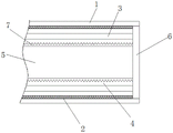
图3为本实用新型的正视剖视结构示意图;Fig. 3 is the front sectional structure schematic diagram of the utility model;
图中:1、PVC外管套;2、连接网;3、岩棉管隔音层;4、聚乙烯保温层;5、钢管体;6、延伸环;7、波浪槽。In the picture: 1. PVC outer pipe sleeve; 2. Connection net; 3. Rock wool pipe sound insulation layer; 4. Polyethylene insulation layer; 5. Steel pipe body; 6. Extension ring; 7. Wave groove.
具体实施方式Detailed ways
下面将结合本实用新型实施例中的附图,对本实用新型实施例中的技术方案进行清楚、完整地描述,显然,所描述的实施例仅仅是本实用新型一部分实施例,而不是全部的实施例。基于本实用新型中的实施例,本领域普通技术人员在没有做出创造性劳动前提下所获得的所有其他实施例,都属于本实用新型保护的范围。The technical solutions in the embodiments of the present utility model will be clearly and completely described below with reference to the accompanying drawings in the embodiments of the present utility model. Obviously, the described embodiments are only a part of the embodiments of the present utility model, rather than all the implementations. example. Based on the embodiments of the present invention, all other embodiments obtained by those of ordinary skill in the art without creative work fall within the protection scope of the present invention.
实施例1Example 1
请参阅图1至图3,本实用新型提供一种技术方案:一种耐挤压的多层复合管,包括钢管体5,钢管体5的外侧固定设置有聚乙烯保温层4,起到保温防冻的作用,聚乙烯保温层4的外侧固定设置有岩棉管隔音层3,起到隔音的作用,岩棉管隔音层3的外侧设置有PVC外管套1,PVC外管套1的内部固定设置有一层连接网2防止PVC外管套1开裂,钢管体5的一端设置有延伸环6,延伸环6延伸至PVC外管套1的端部边缘处,且延伸环6与聚乙烯保温层4、岩棉管隔音层3和PVC外管套1均贴合,起到密封作用。Please refer to FIGS. 1 to 3, the present utility model provides a technical solution: an extrusion-resistant multi-layer composite pipe, comprising a
本实施例中,优选的,钢管体5的外表面设置有波浪槽7,聚乙烯保温层4的外表面与波浪槽7相互贴合,保证粘合紧固。In this embodiment, preferably, the outer surface of the
本实施例中,优选的,PVC外管套1与岩棉管隔音层3通过热熔胶粘合连接,岩棉管隔音层3与聚乙烯保温层4之间也通过热熔胶粘合连接,为了保证连接牢固,保证整体性。In this embodiment, preferably, the PVC
本实施例中,优选的,连接网2为一体式的圆环状结构,且PVC外管套1与连接网2一体成型,为了保证连接牢固。In this embodiment, preferably, the connecting
本实施例中,优选的,延伸环6的端部表面与PVC外管套1的端部表面齐平,为了起到密封的作用,同时齐平便于安装。In this embodiment, preferably, the end surface of the
本实用新型的工作原理及使用流程:在本实用新型的复合管通过在外侧PVC外管套1内设计了连接网2可以起到防止PVC外管套1长期暴露在外部容易开裂的问题;另外在本实用新型中的复合管内层设计的岩棉管隔音层3和聚乙烯保温层4能够能好的起到保温和隔音的效果,并且钢管体5端部设计了延伸环6,延伸环6延伸至PVC外管套2边缘,将连接网2、岩棉管隔音层3和聚乙烯保温层4的端部边缘密封起来,起到密封和防护的作用。The working principle and use process of the present utility model: in the composite pipe of the present utility model, the connecting
尽管已经示出和描述了本实用新型的实施例,对于本领域的普通技术人员而言,可以理解在不脱离本实用新型的原理和精神的情况下可以对这些实施例进行多种变化、修改、替换和变型,本实用新型的范围由所附权利要求及其等同物限定。Although the embodiments of the present invention have been shown and described, it will be understood by those skilled in the art that various changes and modifications can be made to these embodiments without departing from the principles and spirit of the present invention , alternatives and modifications, the scope of the present invention is defined by the appended claims and their equivalents.
Claims (5)
Priority Applications (1)
| Application Number | Priority Date | Filing Date | Title |
|---|---|---|---|
| CN202020370750.9U CN211875322U (en) | 2020-03-23 | 2020-03-23 | An extrusion-resistant multi-layer composite pipe |
Applications Claiming Priority (1)
| Application Number | Priority Date | Filing Date | Title |
|---|---|---|---|
| CN202020370750.9U CN211875322U (en) | 2020-03-23 | 2020-03-23 | An extrusion-resistant multi-layer composite pipe |
Publications (1)
| Publication Number | Publication Date |
|---|---|
| CN211875322U true CN211875322U (en) | 2020-11-06 |
Family
ID=73255987
Family Applications (1)
| Application Number | Title | Priority Date | Filing Date |
|---|---|---|---|
| CN202020370750.9U Expired - Fee Related CN211875322U (en) | 2020-03-23 | 2020-03-23 | An extrusion-resistant multi-layer composite pipe |
Country Status (1)
| Country | Link |
|---|---|
| CN (1) | CN211875322U (en) |
-
2020
- 2020-03-23 CN CN202020370750.9U patent/CN211875322U/en not_active Expired - Fee Related
Similar Documents
| Publication | Publication Date | Title |
|---|---|---|
| JP2010539405A5 (en) | ||
| CN204664650U (en) | For connecting the liner sliding sleeve of two straight tube ends | |
| CN209762471U (en) | High-pressure conveying flexible polyethylene composite pipe | |
| CN204005033U (en) | A kind of thermal insulation pipe | |
| CN207961772U (en) | A kind of direct-buried heat insulation pipe | |
| CN2911362Y (en) | Single layer thermal insulation pipeline structure for offshore transportation of petroleum, natural gas, water and/or oil-gas mixed transportation | |
| CN115468040A (en) | Assembled biodegradable ventilation pipeline | |
| CN204554199U (en) | Socket joint jointing type elbow | |
| CN210978986U (en) | Polyurethane prefabricated direct-buried insulating pipe | |
| CN215060158U (en) | Gas transmission pipeline convenient to clearance | |
| CN209115887U (en) | An insulating high temperature resistant flame retardant Teflon sleeve | |
| CN213685822U (en) | A container thermal insulation structure | |
| CN206770802U (en) | A kind of building water supply and drainage pipeline crosses building conduit | |
| CN206386596U (en) | One kind carries metal reinforcing ring bending rubber joint | |
| CN218208210U (en) | A kind of multi-layer composite pipe | |
| CN215721335U (en) | Petroleum pipeline with compression-resistant effect | |
| CN206191123U (en) | Anti negative pressure flexible rubber joint | |
| CN218845392U (en) | A new type of environmentally friendly pipe | |
| CN221974565U (en) | High-strength multilayer gas pipe | |
| CN202612886U (en) | Polyethylene-aluminum composite pipe | |
| CN217762447U (en) | Petroleum pipeline with high weather resistance and good compression resistance effect | |
| CN221839110U (en) | A high temperature resistant flame retardant PVC pipe | |
| CN110848471A (en) | Novel corrosion-resistant conveying pipe | |
| CN208871215U (en) | A kind of novel environment-friendly tubing | |
| CN204512723U (en) | A kind of rubber lined pipe and end face of flange linkage structure |
Legal Events
| Date | Code | Title | Description |
|---|---|---|---|
| GR01 | Patent grant | ||
| GR01 | Patent grant | ||
| CF01 | Termination of patent right due to non-payment of annual fee |
Granted publication date: 20201106 |
|
| CF01 | Termination of patent right due to non-payment of annual fee |