CN211873476U - Horizontal locking type fully-hidden frame glass curtain wall connecting structure - Google Patents
Horizontal locking type fully-hidden frame glass curtain wall connecting structure Download PDFInfo
- Publication number
- CN211873476U CN211873476U CN202020498530.4U CN202020498530U CN211873476U CN 211873476 U CN211873476 U CN 211873476U CN 202020498530 U CN202020498530 U CN 202020498530U CN 211873476 U CN211873476 U CN 211873476U
- Authority
- CN
- China
- Prior art keywords
- shaped
- glass
- strip
- plate
- transverse
- Prior art date
- Legal status (The legal status is an assumption and is not a legal conclusion. Google has not performed a legal analysis and makes no representation as to the accuracy of the status listed.)
- Expired - Fee Related
Links
- 239000011521 glass Substances 0.000 title claims abstract description 108
- 239000006260 foam Substances 0.000 claims abstract description 7
- 239000000565 sealant Substances 0.000 claims abstract description 7
- 239000002390 adhesive tape Substances 0.000 claims description 7
- 238000009434 installation Methods 0.000 abstract description 16
- 238000010276 construction Methods 0.000 abstract description 5
- 230000009286 beneficial effect Effects 0.000 abstract description 3
- 238000007789 sealing Methods 0.000 abstract description 2
- 239000000853 adhesive Substances 0.000 description 9
- XAGFODPZIPBFFR-UHFFFAOYSA-N aluminium Chemical compound [Al] XAGFODPZIPBFFR-UHFFFAOYSA-N 0.000 description 9
- 229910052782 aluminium Inorganic materials 0.000 description 9
- 230000001070 adhesive effect Effects 0.000 description 8
- 239000010935 stainless steel Substances 0.000 description 7
- 229910001220 stainless steel Inorganic materials 0.000 description 7
- 229910000838 Al alloy Inorganic materials 0.000 description 5
- 239000002808 molecular sieve Substances 0.000 description 2
- 229920001296 polysiloxane Polymers 0.000 description 2
- 238000005553 drilling Methods 0.000 description 1
- 230000000694 effects Effects 0.000 description 1
- 238000006056 electrooxidation reaction Methods 0.000 description 1
- 239000011229 interlayer Substances 0.000 description 1
- 230000035939 shock Effects 0.000 description 1
- URGAHOPLAPQHLN-UHFFFAOYSA-N sodium aluminosilicate Chemical compound [Na+].[Al+3].[O-][Si]([O-])=O.[O-][Si]([O-])=O URGAHOPLAPQHLN-UHFFFAOYSA-N 0.000 description 1
- 238000006467 substitution reaction Methods 0.000 description 1
Images





Landscapes
- Load-Bearing And Curtain Walls (AREA)
Abstract
The utility model discloses a transverse locking type fully-hidden frame glass curtain wall connecting structure, which comprises a group of upright posts, crossbeams vertically connected with two sides of the same vertical plane of the upright posts, glass connected with the outer sides of the upright posts, a pressing plate connected between the glass and the upright posts, and an upper attached frame and a lower attached frame connected between the glass and the crossbeams, wherein the pressing plate is detachably connected with the upright posts through connecting pieces, and the pressing plate is spliced with the glass through the attached frame; the outer end part of the connecting piece is arranged between the glass and the upright post. The utility model is convenient for pre-positioning and accurate installation by arranging the L-shaped hook on the side surface of the beam and matching the upper attached frame and the lower attached frame which are bonded on the inner side of the glass; the arrangement of the auxiliary frame, the connecting piece and the pressing plate is beneficial to clamping and convenient for positioning and accurate installation; the upright posts and the cross beams are connected through the corner pieces, so that the on-site construction and the adjustment and installation are facilitated; the arrangement of the foam rod and the sealant ensures the sealing and connection of the installation splicing seams of the adjacent glass.
Description
Technical Field
The utility model belongs to curtain installation and construction field, in particular to horizontal lock formula hides frame glass curtain wall connection structure entirely.
Background
The curtain wall is an outer wall enclosure of a building and is a light wall with decorative effect commonly used in modern large and high-rise buildings. The building envelope structure consists of a structural frame and an embedded plate, and does not bear the load and the action of a main structure. The main structure of the existing glass curtain wall mostly adopts aluminum alloy upright posts and cross beams, and the cross beams are fixed on the upright posts through angle codes by fixing screws to form a latticed curtain wall framework.
The existing glass curtain wall main body structure is made of aluminum profiles, hollow glass of a structural adhesive sheet is bonded on a glass auxiliary frame through structural adhesive, and is fixed on a vertical column and a cross beam through a pressing plate and stainless steel screws. The structure has the following problems that firstly, the glass curtain wall plate is fixed only by the stainless steel screw, the stainless steel screw and the aluminum profile are in close contact with each other for a long time to generate electrochemical corrosion, aluminum profile screw threads are corroded, the stainless steel screw is loosened and fails, and the glass curtain wall plate can fall off integrally under the action of wind suction force of the curtain wall to generate serious potential safety hazard to the society as a result; secondly, because the strength of the aluminum alloy section is low, the aluminum alloy section is very easily influenced by the positive difference of the diameters of drill bits and the precision of a drilling machine when the aluminum alloy section upright post and the cross beam are tapped by the rotary holes, so that the aluminum alloy upright post and the cross beam are easily loosened when being connected with stainless steel screws; thirdly, when the glass plate of the curtain wall is fixed by the pressing plate and the stainless steel screws, the mounting position can be accurately guaranteed by multiple times of adjustment, labor is wasted, the labor intensity of a mounting worker is greatly improved when the grid of the glass curtain wall is large, the mounting efficiency is low, and the mounting quality is difficult to guarantee.
SUMMERY OF THE UTILITY MODEL
The utility model provides a horizontal lock formula is hidden frame glass curtain wall connection structure entirely for convenient installation when solving the installation of glass curtain wall, multiple fixed and technical problem such as accurate location.
In order to achieve the above purpose, the utility model adopts the following technical scheme:
a transverse locking type fully-hidden frame glass curtain wall connecting structure comprises a group of upright posts, cross beams vertically connected to two sides of the same vertical plane of the upright posts, glass connected to the outer sides of the upright posts, a pressing plate connected between the glass and the upright posts, and an upper auxiliary frame and a lower auxiliary frame connected between the glass and the cross beams;
the pressing plate is detachably connected with the upright post through a connecting piece, and the pressing plate is inserted into the glass through the auxiliary frame; the outer end part of the connecting piece is arranged between the glass and the upright post;
the cross beam comprises a U-shaped part, a group of L-shaped hooks connected to the outer side of one vertical edge of the U-shaped part, a transverse plate connected to the inside of the U-shaped part and a buckle cover connected to the top end of the U-shaped part, the outer end of the transverse part of each L-shaped hook is vertically connected with the vertical edge of the U-shaped part, and the L-shaped hooks are connected with the glass through upper and lower auxiliary frames;
the splicing seams of the adjacent glass are filled and sealed by a foam rod and sealant; the vertical splicing seams of the adjacent glass are arranged at the upright posts, and the transverse splicing seams of the adjacent glass are arranged at the transverse beams.
Furthermore, the cross beam is detachably connected with the upright column, an angle piece is connected between the cross beam and the upright column, and the angle piece is fixedly connected with the upright column and the transverse plate inside the cross beam through connecting bolts respectively.
Furthermore, the buckle cover is a strip-shaped plate, the lower parts of the two transverse ends of the buckle cover are connected with vertical hooks, and the vertical hooks are connected with vertical edges at the tops of U-shaped pieces in the corresponding cross beam in a clamping mode.
Furthermore, the upper auxiliary frame comprises a strip-shaped plate and an L-shaped piece connected to the strip-shaped plate, the vertical part of the L-shaped piece is vertically connected with the strip-shaped plate, the transverse part of the L-shaped piece is parallel to the strip-shaped plate, and the inner side of the outer end of the transverse part is provided with a T-shaped notch; an adhesive tape is connected between the T-shaped notch and the L-shaped hook of the cross beam.
Furthermore, it connects in the vertical upper end inboard of glass to attach the frame on, attaches in the frame strip board not connect L shape one side parallel connection in glass vertical direction, L shape and strip shape connection opening part are downward.
Furthermore, the lower auxiliary frame comprises a strip-shaped plate, a baffle vertically connected to one end of the strip-shaped plate and an L-shaped piece connected to one side of the strip-shaped plate, which is not connected with the baffle, wherein the vertical part of the L-shaped piece is vertically connected with the strip-shaped plate, the transverse part of the L-shaped piece is parallel to the strip-shaped plate, and a T-shaped notch is formed in the inner side of the outer end of the transverse part; an adhesive tape is connected between the T-shaped notch and the L-shaped hook of the cross beam.
Further, attach the frame down and connect in the vertical lower extreme inboard of glass, attach the baffle in the frame down and connect in the vertical lower tip of glass, strip shaped plate parallel connection is inboard in the vertical of glass, and the opening one side that the L shape and strip shaped plate connection formed is downward.
Further, the clamp plate is the bar shaped plate, and the clamp plate is provided with the arc arch to both ends short-cut and closes on stand one side, and the interval is provided with the bar briquetting between two arc archs.
Furthermore, the auxiliary frame is connected to two sides of a splicing seam of adjacent glass at the upright post, and the auxiliary frame is arranged in the vertical direction of the glass in a through manner; the auxiliary frame is a T-shaped piece, and the openings of two adjacent T-shaped pieces are oppositely arranged; one vertical edge of the T-shaped part is connected with the glass in parallel, and the other vertical edge is connected between the upright post and the pressing plate.
Furthermore, the connecting piece is a rod piece, the connecting piece can be disassembled and connected with the pressing plate and the stand column, and the connecting piece penetrates from the outer side of the pressing plate and is connected to the inner part of the stand column.
The beneficial effects of the utility model are embodied in:
1) the utility model can realize the hanging connection of glass during installation by arranging the L-shaped hook on the side surface of the beam and matching with the upper attached frame and the lower attached frame which are bonded on the inner side of the glass, and is convenient for pre-positioning and accurate installation;
2) the utility model is beneficial to realizing the clamping at the upright post when the glass is installed and is convenient for pre-positioning and accurate installation by arranging the auxiliary frame, the connecting piece and the pressing plate; through the combined application of hanging connection and clamping connection, fixation, shock resistance and accurate installation during glass installation are guaranteed;
3) the utility model connects the upright post and the cross beam through the corner fitting, which is convenient for site construction and adjustment and installation; the arrangement of the foam rod and the sealant ensures the sealing and connection of the installation splicing seams of the adjacent glass;
in addition, no matter the glass curtain wall is hung or clamped, the connecting part is hidden inside the glass, and the attractiveness of the glass curtain wall is not affected; the related frameworks can be prefabricated and produced, so that the construction is convenient and fast, and the working hours are saved; additional features and advantages of the invention will be set forth in the description which follows, and in part will be obvious from the description, or may be learned by practice of the invention; the primary objects and other advantages of the invention may be realized and attained by the structure particularly pointed out in the written description.
Drawings
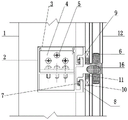
FIG. 1 is a vertical sectional view of a transverse locking type full hidden frame glass curtain wall connecting structure;
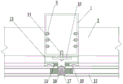
FIG. 2 is a cross sectional view of a cross locking type fully hidden frame glass curtain wall connecting structure;
FIG. 3 is a schematic cross-sectional view of a column;
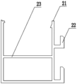
FIG. 4 is a schematic view of a beam construction;
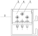
FIG. 5 is a schematic view of a beam connection structure;
FIG. 6 is a schematic view of a buckle cover structure;
FIG. 7 is a schematic view of a corner fitting;
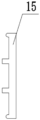
FIG. 8 is a schematic view of a platen configuration;
FIG. 9 is a schematic view of a frame structure;
FIG. 10 is a schematic view of the structure of the upper attached frame;
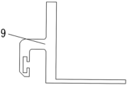
fig. 11 is a schematic view of the structure of the lower attached frame.
Reference numerals: 1-upright column, 2-cross beam, 21-U-shaped piece, 22-L-shaped hook, 23-transverse plate, 3-buckle cover, 4-corner piece, 5-connecting bolt, 6-molecular sieve, 7-adhesive tape, 8-upper attached frame, 9-lower attached frame, 10-adhesive piece, 11-structural adhesive, 12-glass, 13-attached frame, 14-connecting piece, 15-pressing plate, 16-foam rod and 17-sealant.
Detailed Description
Taking a certain hollow glass curtain wall as an example, as shown in fig. 1 and 2, glass 12 is hollow glass, a structural adhesive 11 and a molecular sieve 6 are connected in an interlayer of the glass 12, and a splicing seam between adjacent glass 12 is filled and sealed by a foam rod 16 with the diameter of 20mm and a silicone weather-resistant sealant; the vertical splicing seams of the adjacent glass 12 are arranged at the upright posts 1, and the transverse splicing seams of the adjacent glass 12 are arranged at the cross beams 2.
In this embodiment, the transverse locking type glass curtain wall connecting structure with the fully hidden frame comprises a group of upright posts 1, cross beams 2 vertically connected to two sides of the same vertical plane of the upright posts 1, glass 12 connected to the outer sides of the upright posts 1, a pressing plate 15 connected between the glass 12 and the upright posts 1, and an upper attached frame 8 and a lower attached frame 9 connected between the glass 12 and the cross beams 2.
In this embodiment, the upright columns 1 and the cross beams 2 are made of aluminum sections, the upright columns 1 and the cross beams 2 are arranged in a grid shape or in a net shape according to design requirements, and the upright columns 1 and the cross beams 2 form a frame structure for hanging the glass 12. As shown in fig. 3 and 4, the cross section of the upright post 1 is a square pipe fitting which is prefabricated according to the design height of the glass curtain wall; the cross beam 2 comprises a U-shaped part 21, two L-shaped hooks 22 connected to the outer side of one vertical edge of the U-shaped part 21 and a transverse plate 23 connected to the inner part of the U-shaped part 21, wherein the U-shaped part 21, the L-shaped hooks 22 and the transverse plate 23 in the cross beam 2 are integrally manufactured or are separately manufactured and then welded into a whole. Wherein, the outer end of the horizontal part of the L-shaped hook 22 is vertically connected with the vertical edge of the U-shaped part 21 and the opening is upward, and the L-shaped hook 22 is hooked with the glass 12 through the upper attached frame 8 and the lower attached frame 9.
As shown in fig. 5 and 6, the inside of the top end of the U-shaped member 21 of the cross member 2 is provided with a protrusion; buckle closure 3 is the strip shaped plate, and its horizontal both ends sub-unit connection has the vertical hook, and the vertical hook corresponds the protruding joint in 21 top vertical edges of U-shaped piece in crossbeam 2.
In this embodiment, the cross beam 2 is detachably connected with the upright post 1, and an angle piece 4 is connected between the cross beam 2 and the upright post 1. As shown in fig. 7, the corner fitting 4 is fixedly connected to the vertical column 1 and the cross plate 23 inside the cross beam 2 by the connecting bolt 5. The corner fittings 4 are aluminum corner connectors and are fixed on the upright posts 1 and the cross beams 2 through stainless steel bolts of M5x20mm, so that the upright posts 1 and the cross beams 2 form a complete structural system.
In the embodiment, the pressing plate 15 is detachably connected with the upright post 1 through the connecting piece 14, and the pressing plate 15 is inserted into the glass 12 through the auxiliary frame 13; the outer end part of the connecting piece 14 is arranged between the glass 12 and the upright post 1; as shown in fig. 8, the pressing plate 15 is an aluminum strip-shaped plate, the two ends of the pressing plate 15 in the short direction are close to one side of the upright post 1 and are provided with arc-shaped protrusions, and two strip-shaped pressing blocks are arranged between the two arc-shaped protrusions at intervals. Wherein, connecting piece 14 is the screw rod, and connecting piece 14 threaded connection clamp plate 15 and stand 1, connecting piece 14 penetrate from the clamp plate 15 outside and connect in the inside of stand 1.
In this embodiment, the attached frames 13 are connected to two sides of the splicing seam of the adjacent glass 12 at the upright post 1, and the attached frames 13 are arranged in a full length manner in the vertical direction of the glass 12. As shown in fig. 9, the auxiliary frame 13 is a T-shaped aluminum member, and openings of two adjacent T-shaped members are oppositely arranged; one vertical edge of the T-shaped piece is connected with the glass 12 in parallel, and the other vertical edge is connected between the upright post 1 and the pressing plate 15. The thickness of the two sides of the attached frame 13 is determined according to the distance between the pressure plate 15 and the upright post 1, and the length of the two sides of the attached frame 13 is determined according to the length required by clamping.
As shown in fig. 10, the upper frame 8 is an aluminum profile made integrally, the upper frame 8 includes a strip-shaped plate and an L-shaped member connected to the strip-shaped plate, a vertical portion of the L-shaped member is vertically connected to the strip-shaped plate, a horizontal portion is parallel to the strip-shaped plate, and a T-shaped notch is formed in an inner side of an outer end of the horizontal portion; an adhesive tape 7 is connected between the T-shaped notch and the L-shaped hook 22 of the cross beam 2. Go up and attach frame 8 and connect in the vertical upper end inboard of glass 12, go up and attach frame 8 in the strip board not connect L shape one side parallel connection in glass 12 vertical, L shape and strip board connection opening part are downward.
As shown in fig. 11, the lower attached frame 9 is an aluminum profile, the lower attached frame 9 includes a strip-shaped plate, a baffle plate vertically connected to one end of the strip-shaped plate, and an L-shaped member connected to one side of the strip-shaped plate, the vertical portion of the L-shaped member is vertically connected to the strip-shaped plate, the horizontal portion is parallel to the strip-shaped plate, and a T-shaped notch is formed in the inner side of the outer end of the horizontal portion; an adhesive tape 7 is connected between the T-shaped notch and the L-shaped hook 22 of the cross beam 2. It is inboard that attaches frame 9 down to connect in the vertical lower extreme of glass 12, attaches the baffle in the frame 9 down and connect in the vertical lower tip of glass 12, and strip shaped plate parallel connection is inboard in the vertical of glass 12, and the opening one side that the L shape piece and strip shaped plate connection formed is downward. The glass 12 is respectively connected with the upper attached frame 8, the lower attached frame 9 and the attached frame 13 through the structural adhesive 11 and the adhesive 10, wherein the adhesive 10 is double-faced adhesive.
When the glass is installed and applied, the upright posts 1 and the cross beams 2 are connected through the corner pieces 4 to form a designed net shape or a designed Chinese character 'tian', wherein the L-shaped hooks 22 on the cross beams 2 are determined according to the installation and hanging number of the designed glass 12, and the inner sides of the glass 12 are provided with the auxiliary frames 13, the upper auxiliary frames 8 and the lower auxiliary frames 9 which are numbered and arranged according to the installation sequence; when the glass 12 is installed, a connecting mode of transverse hanging and vertical inserting is adopted to form a full-hidden glass curtain wall, and the assembling seams of the adjacent glass 12 are filled and sealed by a foam rod 16 with the diameter of 20mm and silicone weather-resistant sealant.
The above description is only for the preferred embodiment of the present invention, but the protection scope of the present invention is not limited thereto, and any changes or substitutions that can be considered by those skilled in the art within the technical scope of the present invention should be covered by the protection scope of the present invention.
Claims (10)
1. A transverse locking type fully-hidden frame glass curtain wall connecting structure is characterized by comprising a group of upright posts (1), cross beams (2) vertically connected to two sides of the same vertical plane of the upright posts (1), glass (12) connected to the outer sides of the upright posts (1), a pressing plate (15) connected between the glass (12) and the upright posts (1), and an upper auxiliary frame (8) and a lower auxiliary frame (9) connected between the glass (12) and the cross beams (2);
the pressing plate (15) is detachably connected with the upright post (1) through a connecting piece (14), and the pressing plate (15) is inserted into the glass through an attached frame (13); the outer end part of the connecting piece (14) is arranged between the glass (12) and the upright post (1);
the cross beam (2) comprises a U-shaped part (21), a group of L-shaped hooks (22) connected to the outer side of one vertical edge of the U-shaped part (21), a transverse plate (23) connected to the inside of the U-shaped part (21) and a buckle cover (3) connected to the top end of the U-shaped part (21), the outer end of the transverse part of each L-shaped hook (22) is vertically connected with the vertical edge of the U-shaped part (21), and the L-shaped hooks (22) are connected with the glass (12) in a hanging mode through an upper auxiliary frame (8) and a lower auxiliary frame (9);
the splicing seams of the adjacent glass (12) are filled and sealed by a foam rod (16) and a sealant (17); vertical splicing seams of adjacent glass (12) are arranged at the upright columns (1), and transverse splicing seams of the adjacent glass (12) are arranged at the cross beams (2).
2. The connecting structure of the transverse locking type fully hidden frame glass curtain wall as claimed in claim 1, wherein the transverse beam (2) is detachably connected with the upright post (1), an angle piece (4) is connected between the transverse beam (2) and the upright post (1), and the angle piece (4) is fixedly connected with the upright post (1) and the transverse plate (23) inside the transverse beam (2) respectively through a connecting bolt (5).
3. The connecting structure of the horizontal locking type fully hidden frame glass curtain wall as claimed in claim 2, wherein the buckle cover (3) is a strip-shaped plate, the lower parts of the two horizontal ends of the buckle cover are connected with vertical hooks, and the vertical hooks are clamped and connected with the vertical edges of the tops of the U-shaped pieces (21) in the cross beam (2).
4. The connecting structure of the transverse locking type fully hidden frame glass curtain wall as claimed in claim 1, wherein the upper auxiliary frame (8) comprises a strip-shaped plate and an L-shaped part connected to the strip-shaped plate, the vertical part of the L-shaped part is vertically connected with the strip-shaped plate, the transverse part is parallel to the strip-shaped plate, and the inner side of the outer end of the transverse part is provided with a T-shaped notch; an adhesive tape (7) is connected between the T-shaped notch and the L-shaped hook (22) of the cross beam (2).
5. The connecting structure of the horizontal locking type fully hidden frame glass curtain wall as claimed in claim 4, wherein the upper auxiliary frame (8) is connected to the inner side of the vertical upper end of the glass (12), one side of the upper auxiliary frame (8) which is not connected with the L-shaped piece is connected in parallel with the vertical direction of the glass (12), and the connecting opening of the L-shaped piece and the strip-shaped piece is downward.
6. The connecting structure of the transverse locking type fully hidden frame glass curtain wall as claimed in claim 5, wherein the lower auxiliary frame (9) comprises a strip-shaped plate, a baffle plate vertically connected to one end of the strip-shaped plate and an L-shaped part connected to one side of the strip-shaped plate, the vertical part of the L-shaped part is vertically connected with the strip-shaped plate, the transverse part is parallel to the strip-shaped plate, and the inner side of the outer end of the transverse part is provided with a T-shaped notch; an adhesive tape (7) is connected between the T-shaped notch and the L-shaped hook (22) of the cross beam (2).
7. The connecting structure of the horizontal locking type hidden frame glass curtain wall as claimed in claim 6, wherein the lower auxiliary frame (9) is connected to the inner side of the lower vertical end of the glass (12), the baffle plate in the lower auxiliary frame (9) is connected to the lower vertical end of the glass (12), the strip-shaped plate is connected to the inner side of the glass (12) in parallel, and the L-shaped part is connected with the strip-shaped plate to form an opening with a downward side.
8. The connecting structure of the horizontal locking type fully hidden frame glass curtain wall as claimed in claim 1, wherein the pressing plate (15) is a strip-shaped plate, the side of the pressing plate (15) near the upright post (1) is provided with arc-shaped protrusions at both ends in the short direction, and strip-shaped pressing blocks are arranged between the two arc-shaped protrusions at intervals.
9. The connecting structure of the transverse locking type fully hidden frame glass curtain wall as claimed in claim 8, wherein the auxiliary frames (13) are connected to two sides of the splicing seam of the adjacent glass (12) at the upright post (1), and the auxiliary frames (13) are arranged in a full length mode in the vertical direction of the glass (12); the auxiliary frame (13) is a T-shaped piece, and the openings of two adjacent T-shaped pieces are oppositely arranged; one vertical edge of the T-shaped part is connected with the glass (12) in parallel, and the other vertical edge is connected between the upright post (1) and the pressing plate (15).
10. The connecting structure of the horizontal locking type hidden frame glass curtain wall as claimed in claim 9, wherein the connecting member (14) is a rod member, the connecting member (14) is detachably connected with the pressing plate (15) and the upright post (1), and the connecting member (14) penetrates from the outer side of the pressing plate (15) and is connected with the inside of the upright post (1).
Priority Applications (1)
| Application Number | Priority Date | Filing Date | Title |
|---|---|---|---|
| CN202020498530.4U CN211873476U (en) | 2020-04-08 | 2020-04-08 | Horizontal locking type fully-hidden frame glass curtain wall connecting structure |
Applications Claiming Priority (1)
| Application Number | Priority Date | Filing Date | Title |
|---|---|---|---|
| CN202020498530.4U CN211873476U (en) | 2020-04-08 | 2020-04-08 | Horizontal locking type fully-hidden frame glass curtain wall connecting structure |
Publications (1)
| Publication Number | Publication Date |
|---|---|
| CN211873476U true CN211873476U (en) | 2020-11-06 |
Family
ID=73251197
Family Applications (1)
| Application Number | Title | Priority Date | Filing Date |
|---|---|---|---|
| CN202020498530.4U Expired - Fee Related CN211873476U (en) | 2020-04-08 | 2020-04-08 | Horizontal locking type fully-hidden frame glass curtain wall connecting structure |
Country Status (1)
| Country | Link |
|---|---|
| CN (1) | CN211873476U (en) |
Cited By (1)
| Publication number | Priority date | Publication date | Assignee | Title |
|---|---|---|---|---|
| CN114687557A (en) * | 2022-03-29 | 2022-07-01 | 中建深圳装饰有限公司 | Construction method of ultra-wide and ultra-thick structural adhesive for glass curtain wall |
-
2020
- 2020-04-08 CN CN202020498530.4U patent/CN211873476U/en not_active Expired - Fee Related
Cited By (1)
| Publication number | Priority date | Publication date | Assignee | Title |
|---|---|---|---|---|
| CN114687557A (en) * | 2022-03-29 | 2022-07-01 | 中建深圳装饰有限公司 | Construction method of ultra-wide and ultra-thick structural adhesive for glass curtain wall |
Similar Documents
| Publication | Publication Date | Title |
|---|---|---|
| CN212743079U (en) | Frame type curtain wall | |
| CN106368345A (en) | Assembled non-bearing wall and construction method thereof | |
| CN105971169B (en) | A kind of construction method of assemble net rack shape of the mouth as one speaks aluminum facade system | |
| CN211873477U (en) | Horizontal locking type exposed frame glass curtain wall connecting structure | |
| CN215166952U (en) | Curtain wall with adjustable need not welding and connection structure | |
| CN219863560U (en) | Building curtain wall aluminum veneer of high-efficient installation | |
| CN219491417U (en) | Sealing construction node for outer curtain wall and inner curtain wall at top end part of canopy | |
| CN210194991U (en) | Mounting structure of aluminum plate curtain wall | |
| CN209835337U (en) | Household elevator shaft with glass outer seal and simple and convenient to install | |
| CN215213013U (en) | Hook type curtain wall window | |
| CN213477479U (en) | Novel aluminum plate close-splicing mounting structure | |
| CN216664640U (en) | Non-rib full glass curtain wall upright post combined structure | |
| CN219431123U (en) | Terrazzo face curtain wall construction node | |
| CN216380162U (en) | Novel exposed frame curtain wall structure | |
| CN206143954U (en) | Assembled non -bearing wall body | |
| CN216109256U (en) | Novel waterproof system for curtain wall daylighting roof | |
| CN212129613U (en) | Horizontal-locking type aluminum frame profile horizontal-exposed-vertical-hidden glass curtain wall | |
| CN215331078U (en) | Outdoor open aluminum plate package post system | |
| CN114232850A (en) | Completely-assembled stone, glass and metal curtain wall | |
| CN215166945U (en) | Curtain wall supporting mechanism and curtain wall system | |
| CN219365089U (en) | Closing-in structure of canopy curtain wall below skylight edge | |
| CN111851775A (en) | Waterproof structure of receiving limit of steel construction factory building concrete wall and compound sandwich panel wall handing-over department | |
| CN219753626U (en) | Curtain wall node system | |
| CN221168301U (en) | Transverse large-span grid energy-saving aluminum-clad steel curtain wall structure | |
| CN212715571U (en) | Closing-in structure for curtain wall |
Legal Events
| Date | Code | Title | Description |
|---|---|---|---|
| GR01 | Patent grant | ||
| GR01 | Patent grant | ||
| CF01 | Termination of patent right due to non-payment of annual fee | ||
| CF01 | Termination of patent right due to non-payment of annual fee |
Granted publication date: 20201106 Termination date: 20210408 |