CN211868245U - Automatic glass tube cutting machine - Google Patents
Automatic glass tube cutting machine Download PDFInfo
- Publication number
- CN211868245U CN211868245U CN202020179209.XU CN202020179209U CN211868245U CN 211868245 U CN211868245 U CN 211868245U CN 202020179209 U CN202020179209 U CN 202020179209U CN 211868245 U CN211868245 U CN 211868245U
- Authority
- CN
- China
- Prior art keywords
- plate
- glass tube
- cutting
- rack
- cutting machine
- Prior art date
- Legal status (The legal status is an assumption and is not a legal conclusion. Google has not performed a legal analysis and makes no representation as to the accuracy of the status listed.)
- Expired - Fee Related
Links
- 238000005520 cutting process Methods 0.000 title claims abstract description 74
- 239000011521 glass Substances 0.000 title claims abstract description 67
- 238000003825 pressing Methods 0.000 claims abstract description 28
- 230000005540 biological transmission Effects 0.000 claims description 14
- 210000003811 finger Anatomy 0.000 claims 1
- 210000003813 thumb Anatomy 0.000 claims 1
- 238000004519 manufacturing process Methods 0.000 abstract description 4
- 238000000034 method Methods 0.000 description 4
- 241001391944 Commicarpus scandens Species 0.000 description 1
- 208000027418 Wounds and injury Diseases 0.000 description 1
- 239000004566 building material Substances 0.000 description 1
- 230000006378 damage Effects 0.000 description 1
- 238000010586 diagram Methods 0.000 description 1
- 230000005611 electricity Effects 0.000 description 1
- 230000007613 environmental effect Effects 0.000 description 1
- 208000014674 injury Diseases 0.000 description 1
- 239000000463 material Substances 0.000 description 1
- 238000005272 metallurgy Methods 0.000 description 1
- 230000003287 optical effect Effects 0.000 description 1
- 239000004065 semiconductor Substances 0.000 description 1
- 238000003466 welding Methods 0.000 description 1
Images



Landscapes
- Re-Forming, After-Treatment, Cutting And Transporting Of Glass Products (AREA)
Abstract
本实用新型公开了全自动玻璃管切割机,包括机架,在机架上依次设置放置板、切割装置和掰断装置,切割装置与掰断装置对应设置,在放置板的两侧均设置第一滑轨,第一滑轨设置在所述机架上,在滑轨上滑动连接推动装置,推动装置与所述放置板对应设置,在放置板的一侧对应设置所述切割装置。本实用新型的优点:本装置能够在放置板上放置一组玻璃管,通过推动装置将一组玻璃管推向切割装置,在切割装置进行切割前,通过压紧装置将一组玻璃管压紧,然后对一组玻璃管进行切割,切割后通过玻璃管掰断装置将切割后的玻璃管掰断,掰断后的玻璃管通过横向输送装置下料,本装置实现了同时对多个玻璃管的全自动切割、掰断和下料,提高了玻璃管的生产效率。
The utility model discloses an automatic glass tube cutting machine, which comprises a frame. A placing plate, a cutting device and a breaking device are arranged in sequence on the frame. The cutting device and the breaking device are arranged correspondingly. A sliding rail, the first sliding rail is arranged on the frame, and a pushing device is slidably connected to the sliding rail, the pushing device is arranged corresponding to the placing plate, and the cutting device is correspondingly arranged on one side of the placing plate. The advantages of the utility model: the device can place a group of glass tubes on the placing plate, push a group of glass tubes to the cutting device through the pushing device, and compress a group of glass tubes through the pressing device before cutting by the cutting device. , and then cut a group of glass tubes. After cutting, the cut glass tubes are broken by the glass tube breaking device, and the broken glass tubes are unloaded through the transverse conveying device. Fully automatic cutting, breaking and blanking improves the production efficiency of glass tubes.
Description
技术领域technical field
本实用新型涉及玻璃管生产设备技术领域,尤其涉及全自动玻璃管切割机。The utility model relates to the technical field of glass tube production equipment, in particular to an automatic glass tube cutting machine.
背景技术Background technique
在社会生产生活中,玻璃管的应用非常广泛,它可应用于电光源、半导体、光通信、军工、冶金、建材、化学、机械、电力、环保等各个领域,在现有的玻璃管的加工过程中,通常需要把较长的玻璃管按照规定要求切割成一定的长度,在现有技术中,人们通常是采用玻璃刀人工手动切割玻璃管的,切割玻璃管时,通常会因玻璃刀的切割压力过大而导致玻璃管破碎,不仅浪费了材料,同时还可能造成操作人员手部受伤,采用手工切割的方法不仅效率低下,而且玻璃管在手动切割过后还需手动掰断,工序繁杂,自动化程度低,导致工作效率低下。In social production and life, glass tubes are widely used in various fields such as electric light sources, semiconductors, optical communications, military industry, metallurgy, building materials, chemistry, machinery, electricity, and environmental protection. In the process, it is usually necessary to cut a long glass tube into a certain length according to the specified requirements. In the prior art, people usually use a glass knife to manually cut the glass tube manually. The glass tube is broken due to excessive cutting pressure, which not only wastes materials, but also may cause operator injury to the hands. The manual cutting method is not only inefficient, but also the glass tube needs to be manually broken after manual cutting, and the process is complicated. Low degree of automation leads to low work efficiency.
实用新型内容Utility model content
本实用新型的目的是为了解决现有技术中存在的缺点,而提出的全自动玻璃管切割机。The purpose of the utility model is to propose a fully automatic glass tube cutting machine in order to solve the shortcomings existing in the prior art.
为了实现上述目的,本实用新型采用了如下技术方案:In order to achieve the above-mentioned purpose, the utility model adopts the following technical solutions:
全自动玻璃管切割机,包括机架,在机架上依次设置放置板、切割装置和掰断装置,切割装置与所述掰断装置对应设置,在放置板的两侧均设置第一滑轨,第一滑轨设置在所述机架上,在第一滑轨上滑动连接推动装置,推动装置与所述放置板对应设置,在放置板的一侧对应设置所述切割装置;A fully automatic glass tube cutting machine, including a frame, a placing plate, a cutting device and a breaking device are arranged in sequence on the frame, the cutting device is arranged corresponding to the breaking device, and first slide rails are arranged on both sides of the placing plate , the first sliding rail is arranged on the frame, the first sliding rail is slidably connected to a pushing device, the pushing device is arranged corresponding to the placing plate, and the cutting device is correspondingly arranged on one side of the placing plate;
所述切割装置包括支架,支架连接在所述机架上,在支架上滑动连接移动板,在移动板上连接平板,在平板上设置用于驱动所述移动板的第一驱动装置,在移动板的侧面滑动连接刀盒,在刀盒的下方连接切割刀,切割刀对应设置在所述放置板的一侧上方;The cutting device includes a bracket, the bracket is connected to the frame, the bracket is slidably connected to a moving plate, the moving plate is connected to a flat plate, a first driving device for driving the moving plate is arranged on the flat plate, and the moving plate is The side of the board is slidably connected to the knife box, and the cutting knife is connected to the lower part of the knife box, and the cutting knife is correspondingly arranged above one side of the placing board;
所述掰断装置包括两个固定架,两个固定架均连接在所述机架上,在两个固定架之间转动连接转动架,在转动架上连接掰断压板,掰断压板对应设置在所述放置板的一侧上方,在两个固定架之间还设置第一驱动件,第一驱动件连接在所述机架的侧面上,第一驱动件用于驱动连接所述转动架。The breaking device includes two fixing frames, both of which are connected to the frame, a turret is rotatably connected between the two fixing frames, a breaking pressure plate is connected to the turret, and the breaking pressure plate is correspondingly arranged. Above one side of the placing plate, a first driving member is further arranged between the two fixing frames, the first driving member is connected to the side of the frame, and the first driving member is used for drivingly connecting the turret .
所述推动装置包括滑动架,在滑动架上设有第二驱动装置,第二驱动装置用于驱动所述滑动架,在滑动架上设置第二驱动件,第二驱动件驱动连接压板,压板设置在所述放置板的上方。The pushing device includes a sliding frame, a second driving device is arranged on the sliding frame, the second driving device is used to drive the sliding frame, a second driving member is arranged on the sliding frame, and the second driving member drives the connection pressing plate, the pressing plate set above the placement plate.
优选地,在所述机架上设置横向输送装置,横向输送装置对应设置在所述放置板的一侧,在机架内设置第三驱动装置,第三驱动装置通过皮带皮带轮驱动所述横向输送装置,横向输送装置的输送方向与所述推动装置的推动方向垂直设置。Preferably, a transverse conveying device is arranged on the frame, the transverse conveying device is correspondingly arranged on one side of the placing plate, and a third driving device is arranged in the frame, and the third driving device drives the transverse conveying through a belt pulley The conveying direction of the transverse conveying device is perpendicular to the pushing direction of the pushing device.
优选地,所述第一驱动装置包括第一电机,第一电机的输出轴向下穿过所述平板,在第一电机的输出轴上连接第一齿轮,与第一齿轮啮合的第一齿条板连接在所述支架上。Preferably, the first driving device includes a first motor, the output shaft of the first motor passes downward through the flat plate, the output shaft of the first motor is connected with a first gear, and the first gear meshes with the first gear. A strip is attached to the bracket.
优选地,在所述刀盒的侧面连接滑块,在所述移动板的侧面连接第二滑轨,在第二滑轨上滑动连接所述滑块,在所述平板上设有用于调节所述滑块高度的调节机构。Preferably, a sliding block is connected to the side of the knife box, a second sliding rail is connected to the side of the moving plate, and the sliding block is slidably connected to the second sliding rail. The adjustment mechanism for the height of the slider.
优选地,所述转动架包括两个转动杆,在两个转动杆之间的一端连接连接板,另一端连接所述掰断压板,所述第一驱动件驱动连接连接板,在两个转动杆相对的侧面上均连接转动轴,每个传动轴均插接轴承座,每个轴承座均连接在相应额所述固定架上。Preferably, the rotating frame includes two rotating rods, one end between the two rotating rods is connected to the connecting plate, and the other end is connected to the breaking pressure plate, the first driving member drives the connecting connecting plate, and the two rotating rods are connected to the connecting plate at the other end. The opposite sides of the rod are connected with rotating shafts, each transmission shaft is inserted into a bearing seat, and each bearing seat is connected with the corresponding fixing frame.
优选地,所述滑动架包括支撑板,在支撑板上连接所述第二驱动件,在支撑板的两端均连接L型板,在每个L型板的下方均连接导轨滑块,导轨滑块在相应的所述第一滑轨上滑动连接,在其中一个L型板的水平面上设置所述第二驱动装置。Preferably, the sliding frame includes a support plate, the second drive member is connected to the support plate, L-shaped plates are connected to both ends of the support plate, and rail sliders are connected to the bottom of each L-shaped plate. The sliding blocks are slidably connected on the corresponding first sliding rails, and the second driving device is arranged on the horizontal plane of one of the L-shaped plates.
优选地,在所述支撑板的下方连接竖板,在竖板的侧面下方连接推板,推板用于推动玻璃管。Preferably, a vertical plate is connected below the support plate, and a push plate is connected below the side surface of the vertical plate, and the push plate is used to push the glass tube.
优选地,所述第二驱动装置包括第二电机,第二电机的输出轴向下穿过相应的所述L型板的水平面,在第二电机的输出轴上连接第二齿轮,与第二齿轮啮合的第二齿条连接在所述机架上。Preferably, the second driving device includes a second motor, the output shaft of the second motor passes downward through the corresponding horizontal plane of the L-shaped plate, and the output shaft of the second motor is connected with a second gear, which is connected with the second motor. A second rack in gear engagement is connected to the frame.
优选地,在所述机架上还设置压紧装置,压紧装置对应设置在所述放置板的一侧,所述压紧装置包括两个底板,两个底板分别设置在所述放置板的两侧,在每个底板的上方均连接立柱,在两个立柱之间连接第一顶板,在第一顶板上连接第三驱动件,第三驱动件驱动连接上压料板,在两个底板之间还连接下压料板,下压料板设置在所述上压料板的下方。Preferably, a pressing device is further provided on the frame, the pressing device is correspondingly arranged on one side of the placing plate, the pressing device includes two bottom plates, and the two bottom plates are respectively arranged on the side of the placing plate. On both sides, a column is connected above each bottom plate, a first top plate is connected between the two columns, a third driving member is connected to the first top plate, and the third driving member is drivingly connected to the upper pressing plate, and between the two bottom plates A lower pressing plate is also connected therebetween, and the lower pressing plate is arranged below the upper pressing plate.
优选地,在每个所述底板的上方还设置支撑板,在两个支撑板之间连接切割平台轴,切割平台轴的上方圆弧面与所述下压料板的上方侧面平齐,切割平台轴设置在切割刀的下方。Preferably, a support plate is further arranged above each of the bottom plates, a cutting platform shaft is connected between the two support plates, and the upper arc surface of the cutting platform shaft is flush with the upper side surface of the lower pressing plate, and the cutting The platform axis is arranged below the cutting knife.
本实用新型的优点在于:本实用新型所提供的全自动玻璃管切割机能够在放置板上放置一组玻璃管,通过推动装置将一组玻璃管推向切割装置,在切割装置进行切割前,通过压紧装置将一组玻璃管压紧,然后对一组玻璃管进行切割,切割后通过玻璃管掰断装置将切割后的玻璃管掰断,掰断后的玻璃管通过横向输送装置下料,本装置实现了同时对多个玻璃管的全自动切割、掰断和下料,提高了玻璃管的生产效率。The advantage of the utility model is that the automatic glass tube cutting machine provided by the utility model can place a group of glass pipes on the placing plate, and push the group of glass pipes to the cutting device through the pushing device. Before the cutting device cuts, A group of glass tubes is compressed by a pressing device, and then a group of glass tubes is cut. After cutting, the cut glass tubes are broken by a glass tube breaking device, and the broken glass tubes are unloaded through a transverse conveying device. The device realizes automatic cutting, breaking and unloading of multiple glass tubes at the same time, and improves the production efficiency of the glass tubes.
附图说明Description of drawings
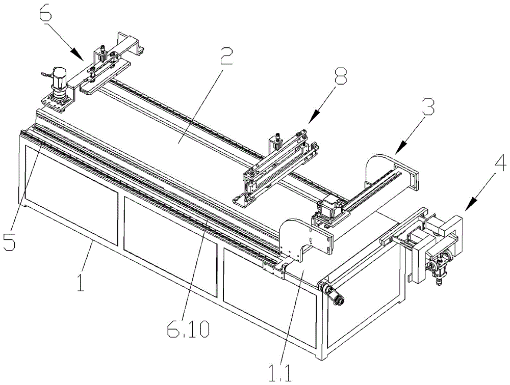
图1是本实用新型所提供的全自动玻璃管切割机的原理结构示意图;Fig. 1 is the principle structure schematic diagram of the automatic glass tube cutting machine provided by the utility model;
图2是切割装置的结构示意图;Fig. 2 is the structural representation of cutting device;
图3是图2的A部放大图;Fig. 3 is the enlarged view of A part of Fig. 2;
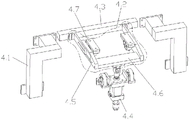
图4是掰断装置的结构示意图;Fig. 4 is the structural representation of breaking device;
图5是推动装置的结构示意图;Fig. 5 is the structural representation of pushing device;
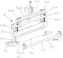
图6是压紧装置的结构示意图。FIG. 6 is a schematic view of the structure of the pressing device.
具体实施方式Detailed ways
为了使本实用新型的目的、技术方案及优点更加清楚明白,以下结合附图及实施例,对本实用新型进行进一步详细说明。应当理解,此处所描述的具体实施例仅仅用以解释本实用新型,并不用于限定本实用新型。In order to make the purpose, technical solutions and advantages of the present utility model more clearly understood, the present utility model will be further described in detail below with reference to the accompanying drawings and embodiments. It should be understood that the specific embodiments described herein are only used to explain the present invention, and are not intended to limit the present invention.
如图1所示,本实用新型提供的全自动玻璃管切割机,包括机架1,在机架1上通过角板焊接放置板2,放置板2用于放置玻璃管,放置板2可以为平面板、弧形板和波浪形板,在本实施例中放置板2采用平面板,在放置板2上放置一排玻璃管。As shown in FIG. 1 , the fully automatic glass tube cutting machine provided by the present invention includes a frame 1, and a
在放置板2的两侧均焊接第一滑轨5,第一滑轨5与放置板2平行设置,第一滑轨5设置在所述机架1上,在第一滑轨5上滑动连接推动装置6,推动装置6与所述放置板2对应设置。The first sliding rails 5 are welded on both sides of the placing
如图5所示,所述推动装置6包括滑动架6.1,所述滑动架6.1包括支撑板6.4,在支撑板6.4的两端均焊接L型板6.5,在每个L型板6.5的下方均焊接导轨滑块6.6,导轨滑块6.6在相应的所述第一滑轨5上滑动连接,在其中一个L型板6.5的水平面上设置所述第二驱动装置,第二驱动装置可以采用蜗轮蜗杆传动、螺杆螺母传动、皮带皮带轮传动或者齿轮齿条传动等多种方式,在本实施例中优选为齿轮齿条传动,即第二驱动装置包括第二电机6.9,第二电机6.9通过螺栓固定在其中一个L型板6.5的水平面上,在第二电机6.9的输出轴向下穿过相应的所述L型板6.5的水平面,在第二电机6.9的输出轴上焊接第二齿轮,与第二齿轮啮合的第二齿条6.10焊接在所述机架1上,通过第二电机6.9带动第二齿轮转动,第二齿轮与第二齿条6.10啮合传动,从而带动滑动架6.1在第一滑轨5上滑动。As shown in FIG. 5 , the pushing device 6 includes a sliding frame 6.1, and the sliding frame 6.1 includes a supporting plate 6.4. L-shaped plates 6.5 are welded on both ends of the supporting plate 6.4, and L-shaped plates 6.5 are welded under each L-shaped plate 6.5. Weld the guide rail slider 6.6, the guide rail slider 6.6 is slidably connected on the corresponding first slide rail 5, and the second drive device is arranged on the horizontal plane of one of the L-shaped plates 6.5, and the second drive device can be a worm gear and worm. Transmission, screw and nut transmission, belt pulley transmission or rack and pinion transmission, etc., in this embodiment, it is preferably a rack and pinion transmission, that is, the second driving device includes a second motor 6.9, and the second motor 6.9 is fixed on the On the horizontal plane of one of the L-shaped plates 6.5, the output shaft of the second motor 6.9 passes downward through the horizontal plane of the corresponding L-shaped plate 6.5, and a second gear is welded on the output shaft of the second motor 6.9, which is connected with the second gear. The second gear rack 6.10 meshed with gears is welded on the frame 1, and the second gear is driven to rotate by the second motor 6.9, and the second gear meshes with the second rack 6.10, thereby driving the sliding frame 6.1 on the first slide rail. 5 swipe up.
在支撑板6.4上连接第二驱动件6.2,第二驱动件6.2可以为气缸或者油缸,在本实施例中第二驱动件6.2为第二气缸,第二气缸竖直向下设置,第二驱动件6.2通过螺栓固定在气缸底座上,气缸底座焊接在支撑板6.4上,在第二驱动件6.2的活塞杆上连接压板6.3,压板6.3用于压紧玻璃管,为了防止压坏玻璃管,在压板6.3的侧面通过螺栓固定橡胶压条6.14。A second driving member 6.2 is connected to the support plate 6.4. The second driving member 6.2 can be an air cylinder or an oil cylinder. In this embodiment, the second driving member 6.2 is a second air cylinder. The second air cylinder is arranged vertically downward. Part 6.2 is fixed on the cylinder base by bolts, the cylinder base is welded on the support plate 6.4, and the pressure plate 6.3 is connected to the piston rod of the second driving part 6.2, and the pressure plate 6.3 is used to compress the glass tube. The side of the pressure plate 6.3 is bolted to the rubber pressure strip 6.14.
为了第二驱动件6.2在带动压板6.3上下移动时,能够更顺畅,压板6.3不会晃动,在本实施例中,在支撑板6.4的侧面通过螺栓固定导向板6.11,在导向板6.11上开设两个导向孔,在每个导向孔内均插接导向轴,两个导向轴的下端均焊接在压板6.3的上方,两个导向轴的上端均焊接第二顶板6.12,在第二顶板6.12上焊接第二驱动件6.2的活塞杆,在每个导向轴上均套接第一导向套6.13,第一导向套6.13设置在导向板6.10与第二顶板6.1之间。In this embodiment, the guide plate 6.11 is fixed by bolts on the side of the support plate 6.4, and two guide plates 6.11 are provided on the guide plate 6.11 so that the second driving member 6.2 can drive the pressure plate 6.3 to move up and down more smoothly. A guide hole is inserted into each guide hole, the lower ends of the two guide shafts are welded above the pressing plate 6.3, and the upper ends of the two guide shafts are welded to the second top plate 6.12, which is welded on the second top plate 6.12 The piston rod of the second driving member 6.2 is sleeved with a first guide sleeve 6.13 on each guide shaft, and the first guide sleeve 6.13 is arranged between the guide plate 6.10 and the second top plate 6.1.
在支撑板6.4的下方焊接竖板6.7,在竖板6.7的侧面下方焊接推板6.8,推板6.8用于推动玻璃管。A vertical plate 6.7 is welded under the support plate 6.4, and a push plate 6.8 is welded under the side surface of the vertical plate 6.7, and the push plate 6.8 is used to push the glass tube.
如图1和图2所示,在机架1上还设置切割装置3和掰断装置4,切割装置3与所述掰断装置4对应设置,在放置板2的一侧对应设置所述切割装置3,所述切割装置3包括支架3.1,支架3.1为现有的,即包括两个横梁固定板3.11,两个横梁固定板3.11分别通过螺栓固定在机架1的两侧,在两个横梁固定板3.11之间焊接横梁3.12,在横梁3.12的侧面焊接两个第三滑轨3.13,在每个第三滑轨3.13上均滑动连接第三滑轨滑块3.14,在两个第三滑轨滑块3.14的侧面焊接移动板3.2,在移动板3.2上焊接平板3.3,在平板3.3上设置用于驱动所述移动板3.2的第一驱动装置。As shown in FIGS. 1 and 2 , a
第一驱动装置可以采用蜗轮蜗杆传动、螺杆螺母传动、皮带皮带轮传动或者齿轮齿条传动等多种方式,在本实施例中优选为齿轮齿条传动,即所述第一驱动装置包括第一电机3.5,第一电机3.5通过螺栓固定在平板3.3上,第一电机3.5的输出轴向下穿过所述平板3.3,在第一电机3.5的输出轴上焊接第一齿轮3.6,与第一齿轮3.6啮合的第一齿条板3.7焊接在横梁3.12上。The first driving device can adopt various modes such as worm gear drive, screw nut drive, belt pulley drive, or rack and pinion drive. In this embodiment, it is preferably a rack and pinion drive, that is, the first drive device includes a first motor. 3.5, the first motor 3.5 is fixed on the flat plate 3.3 by bolts, the output shaft of the first motor 3.5 passes downward through the flat plate 3.3, the first gear 3.6 is welded on the output shaft of the first motor 3.5, and the first gear 3.6 The meshed first rack plate 3.7 is welded to the beam 3.12.
在移动板3.2的侧面滑动连接刀盒3.4,在所述刀盒3.4的侧面焊接滑块3.8,在所述移动板3.2的侧面焊接第二滑轨3.9,在第二滑轨3.9上滑动连接所述滑块3.8,在所述平板3.3上设有用于调节所述滑块3.8高度的调节机构3.10,调节机构3.10可以采用气缸、油缸或者螺纹螺孔的传动方式,在本实施例中调节机构10采用螺纹螺孔的传动方式,如图3所示,即调节机构3.10包括调节螺杆3.15,在调节螺杆3.15的上端焊接旋钮3.16,在滑块3.8上设有与调节螺杆3.15螺纹连接的螺孔,在平板3.3上焊接限位板3.17,在限位板3.17上设有用于穿过调节螺杆3.15的通孔,通过旋钮3.16带动调节螺杆3.15转动,调节螺杆3.15带动滑块3.8移动,从而调节刀盒3.4的高度。Slide and connect the knife box 3.4 on the side of the moving plate 3.2, weld the slider 3.8 on the side of the knife box 3.4, weld the second slide rail 3.9 on the side of the moving plate 3.2, and slide on the second slide rail 3.9 to connect the The slider 3.8 is provided with an adjustment mechanism 3.10 for adjusting the height of the slider 3.8 on the flat plate 3.3. The adjustment mechanism 3.10 can be driven by a cylinder, an oil cylinder or a threaded screw hole. In this embodiment, the
在刀盒3.4的下方连接切割刀7,切割刀7对应设置在所述放置板2的一侧上方,通过第一电机3.5能够带动第一齿轮3.6转动,第一齿轮3.6与第一齿条板3.7啮合,从而带动切割刀7进行移动切割。A cutting knife 7 is connected below the knife box 3.4. The cutting knife 7 is correspondingly arranged above one side of the placing
如图4所示,所述掰断装置4包括两个固定架4.1,两个固定架4.1均焊接在所述机架1上,在两个固定架4.1之间转动连接转动架4.2,所述转动架4.2包括两个转动杆4.5,在两个转动杆4.5之间的一端焊接连接板4.6,另一端焊接掰断压板4.3,转动杆4.5为伸缩杆,通过伸缩杆能够调整长度,便于掰断压板4.3掰断玻璃管。As shown in FIG. 4 , the breaking device 4 includes two fixing frames 4.1, both of which are welded on the frame 1, and a rotating frame 4.2 is rotatably connected between the two fixing frames 4.1. The turret 4.2 includes two rotating rods 4.5. One end of the two rotating rods 4.5 is welded with a connecting plate 4.6, and the other end is welded and broken off the pressure plate 4.3. The rotating rod 4.5 is a telescopic rod, and the length can be adjusted through the telescopic rod, which is easy to break. Press plate 4.3 to break the glass tube.
在两个固定架4.1之间还设置第一驱动件4.4,第一驱动件4.4可以为气缸或者油缸,在本实施例中为第一驱动件4.4为第一气缸,第一气缸通过气缸座焊接在机架1上,第一驱动件4.4的活塞杆铰接驱动连接板4.6,在两个转动杆4.5相对的侧面上均焊接转动轴,每个传动轴均插接轴承座4.7,每个轴承座4.7均焊接在相应的所述固定架4.1上,通过第一驱动件4.4带动连接板4.6向上移动,转动杆4.5以轴承座4.7为转动点,带动掰断压板4.3向下移动掰断玻璃管。A first driving member 4.4 is also arranged between the two fixing frames 4.1. The first driving member 4.4 can be a cylinder or an oil cylinder. In this embodiment, the first driving member 4.4 is a first cylinder, and the first cylinder is welded by the cylinder seat. On the frame 1, the piston rod of the first driving member 4.4 is hinged to drive the connecting plate 4.6, the rotating shafts are welded on the opposite sides of the two rotating rods 4.5, and each transmission shaft is inserted into the bearing seat 4.7, each bearing seat 4.7 4.7 are welded on the corresponding fixing frame 4.1, the connecting plate 4.6 is driven upward by the first driving member 4.4, and the rotating rod 4.5 takes the bearing seat 4.7 as the rotation point, and drives the breaking pressure plate 4.3 to move downward to break the glass tube.
如图6所示,为了防止玻璃管在切割和掰断时发生移动,在机架1上还设置压紧装置8,压紧装置8对应设置在所述放置板2的一侧,所述压紧装置8包括两个底板8.1,两个底板8.1焊接在机架1的上方,两个底板8.1分别设置在所述放置板2的两侧,在每个底板8.1的上方均焊接立柱8.2,在两个立柱8.2之间的上方焊接第一顶板8.3,在第一顶板8.3上连接第三驱动件8.4,第三驱动件8.4可以为气缸或者油缸,在本实施例中第三驱动件8.4为第三气缸,第三气缸通过螺栓固定在气缸座上,气缸座通过螺栓固定在第一顶板8.3上,在第三驱动件8.4的活塞杆上连接上压料板8.5,即在第三驱动件8.4的活塞杆的下方焊接拉升板8.12,在拉升板8.12上设有两个第一螺纹通孔,在每个第一螺纹通孔内均螺纹连接导向螺杆8.13,在导向螺杆8.13向下依次穿过第一顶板8.3,在导向螺杆8.13的下端连接所述上压料板8.5,即在上压料板8.5上设有用于螺纹连接导向螺杆8.13的螺纹盲孔。As shown in FIG. 6 , in order to prevent the glass tube from moving during cutting and breaking, a
在两个底板8.1之间还焊接下压料板8.6,下压料板8.6设置在所述上压料板8.5的下方,通过上压料板8.5向下移动,使上压料板8.5与下压料板8.6之间压紧玻璃管。A lower pressing plate 8.6 is also welded between the two bottom plates 8.1. The lower pressing plate 8.6 is arranged below the upper pressing plate 8.5. Press the glass tube between the pressing plates 8.6.
为了使上压料板8.5在移动时不会发生晃动,在本实施例中,在上压料板8.5的侧面焊接两个导向滑轨8.9,在每个导向滑轨8.9上均滑动连接导向块8.10,每个导向块8.10均焊接在相应的立柱8.2上,在第一顶板8.3上设有两个第二螺纹通孔,在每个第二螺纹通孔内均螺纹连接固定螺栓8.11,在每个固定螺栓8.11上均设有导向通孔,在每个导向通孔内均所述导向螺杆8.13,在每个第二螺纹通孔的一侧均设有安装孔,在每个安装孔内均通孔螺栓固定第二导向套8.14,在每个第二导向套8.14内均插接导向杆8.15,每个导向杆8.15均通过接头固定在拉升板8.12上。In order to prevent the upper pressing plate 8.5 from shaking when moving, in this embodiment, two guide rails 8.9 are welded on the side of the upper pressing plate 8.5, and guide blocks are slidably connected to each guide rail 8.9. 8.10, each guide block 8.10 is welded on the corresponding column 8.2, two second threaded through holes are provided on the first top plate 8.3, and the fixing bolts 8.11 are threaded in each second threaded through hole, and each Each of the fixing bolts 8.11 is provided with guide through holes, the guide screws 8.13 are located in each guide through hole, and a mounting hole is provided on one side of each second threaded through hole, and each mounting hole is provided with a mounting hole. The second guide sleeves 8.14 are fixed with through-hole bolts, and guide rods 8.15 are inserted into each of the second guide sleeves 8.14, and each guide rod 8.15 is fixed on the pulling plate 8.12 through a joint.
在每个底板8.1的上方还焊接支撑板8.7,在两个支撑板8.7之间焊接切割平台轴8.8,切割平台轴8.8的上方圆弧面与所述下压料板8.6的上方侧面平齐,切割平台轴8.8设置在切割刀的下方,使玻璃管处于切割平台轴8.8上,然后切割刀切割玻璃管。A support plate 8.7 is also welded above each bottom plate 8.1, a cutting platform shaft 8.8 is welded between the two support plates 8.7, and the upper arc surface of the cutting platform shaft 8.8 is flush with the upper side of the lower pressing plate 8.6, The cutting platform axis 8.8 is arranged below the cutting knife, so that the glass tube is on the cutting platform axis 8.8, and then the cutting knife cuts the glass tube.
在玻璃管切割掰断后为了更方便的下料,在所述机架1上还设置横向输送装置1.1,横向输送装置1.1对应设置在所述放置板2的一侧,横向输送装置1.1的输送方向与所述推动装置的推动方向垂直设置,横向输送装置1.1为输送带,输送带包括主动轮。从动轮和皮带,在机架1上通过螺栓固定两组轴承座,每组轴承座为两个,在一组轴承座之间转动主动轮,在另一端轴承座之间转动从动轮。After the glass tube is cut and broken, a transverse conveying device 1.1 is also provided on the frame 1, and the transverse conveying device 1.1 is correspondingly arranged on one side of the placing
在机架1内设置第三驱动装置,第三驱动装置可以采用蜗轮蜗杆传动、螺杆螺母传动、皮带皮带轮传动或者齿轮齿条传动等多种方式,在本实施例中第三驱动装置采用皮带皮带轮传动,即第三驱动装置包括第三电机,第三电机通过螺栓固定在机架1内,在第三电机的输出轴穿过机架1的侧壁,在第三电机的输出轴上焊接第一皮带轮,在主动轮的一端焊接第二皮带轮,在第一皮带轮和第二皮带轮之间套接皮带,通过第三电机带动第一皮带轮转动,第一皮带轮带动第二皮带轮转动,第二皮带轮带动主动轮转动,主动轮带动输送带,从输送掰断后的玻璃管。A third driving device is arranged in the frame 1. The third driving device can adopt various modes such as worm gear transmission, screw nut transmission, belt pulley transmission or rack and pinion transmission. In this embodiment, the third driving device adopts a belt pulley. Transmission, that is, the third drive device includes a third motor, the third motor is fixed in the frame 1 by bolts, the output shaft of the third motor passes through the side wall of the frame 1, and the output shaft of the third motor is welded. A pulley, a second pulley is welded to one end of the driving pulley, a belt is sleeved between the first pulley and the second pulley, the first pulley is driven to rotate by the third motor, the first pulley drives the second pulley to rotate, and the second pulley drives The driving wheel rotates, and the driving wheel drives the conveyor belt to transport the broken glass tube.
工作原理:首先将一排玻璃管放置在放置板2上,使一排玻璃管的一端抵在推板6.8的侧面,启动第二驱动件6.2带动压板6.3向下移动从而压紧玻璃管,然后启动第二电机6.9,通过第二电机6.9带动第二齿轮转动,第二齿轮与第二齿条6.10啮合传动,从而带动玻璃管向玻璃切割装置3移动,在移动一定距离后,使玻璃管的切割线处于切割平台轴8.8上,启动第三驱动件8.4带动上压料板8.5向下移动,使上压料板8.5与下压料板8.6之间压紧玻璃管,根据玻璃管的直径,通过调节机构10调节切割刀的高度,接着启动第一电机3.5带动切割刀对玻璃管进行切割,再启动第一驱动件4.4带动连接板4.6向上移动,转动杆4.5以轴承座4.7为转动点,带动掰断压板4.3向下移动掰断玻璃管,掰断后的玻璃管落在横向输送装置1.1上进行下料。Working principle: first place a row of glass tubes on the placing
Claims (10)
Priority Applications (1)
| Application Number | Priority Date | Filing Date | Title |
|---|---|---|---|
| CN202020179209.XU CN211868245U (en) | 2020-02-18 | 2020-02-18 | Automatic glass tube cutting machine |
Applications Claiming Priority (1)
| Application Number | Priority Date | Filing Date | Title |
|---|---|---|---|
| CN202020179209.XU CN211868245U (en) | 2020-02-18 | 2020-02-18 | Automatic glass tube cutting machine |
Publications (1)
| Publication Number | Publication Date |
|---|---|
| CN211868245U true CN211868245U (en) | 2020-11-06 |
Family
ID=73253078
Family Applications (1)
| Application Number | Title | Priority Date | Filing Date |
|---|---|---|---|
| CN202020179209.XU Expired - Fee Related CN211868245U (en) | 2020-02-18 | 2020-02-18 | Automatic glass tube cutting machine |
Country Status (1)
| Country | Link |
|---|---|
| CN (1) | CN211868245U (en) |
Cited By (2)
| Publication number | Priority date | Publication date | Assignee | Title |
|---|---|---|---|---|
| CN111136806A (en) * | 2020-02-18 | 2020-05-12 | 安徽瑞龙玻璃机械股份有限公司 | Full-automatic glass tube cutting machine |
| CN113320029A (en) * | 2021-06-18 | 2021-08-31 | 浙江长兴诺万特克玻璃有限公司 | Continuous production equipment and method for microcrystalline glass |
-
2020
- 2020-02-18 CN CN202020179209.XU patent/CN211868245U/en not_active Expired - Fee Related
Cited By (3)
| Publication number | Priority date | Publication date | Assignee | Title |
|---|---|---|---|---|
| CN111136806A (en) * | 2020-02-18 | 2020-05-12 | 安徽瑞龙玻璃机械股份有限公司 | Full-automatic glass tube cutting machine |
| CN111136806B (en) * | 2020-02-18 | 2024-09-06 | 安徽瑞龙玻璃机械股份有限公司 | Full-automatic glass tube cutting machine |
| CN113320029A (en) * | 2021-06-18 | 2021-08-31 | 浙江长兴诺万特克玻璃有限公司 | Continuous production equipment and method for microcrystalline glass |
Similar Documents
| Publication | Publication Date | Title |
|---|---|---|
| CN111136806B (en) | Full-automatic glass tube cutting machine | |
| CN207787843U (en) | Seamless steel tube production cutter device | |
| CN215880134U (en) | High-precision aluminum product cutting machine | |
| CN108748423A (en) | A kind of plate shearing machine | |
| CN109702268B (en) | Automatic metal pipe clamping and cutting mechanism with material receiving groove body | |
| CN111136805A (en) | Cutting device of full-automatic glass tube cutting machine | |
| CN115415607A (en) | Cutting device for sheet metal part machining | |
| CN115533182A (en) | Movable column type gantry machining center shearing device | |
| CN211762633U (en) | Cutting device of full-automatic glass tube cutting machine | |
| CN212823017U (en) | Alloy pipe cutting device | |
| CN221695466U (en) | Synchronous cutting machine | |
| CN221494870U (en) | PCBA board paster welding set | |
| CN218946501U (en) | Metal cutting processing device | |
| CN218745221U (en) | Improved generation slitting saw device of panel production | |
| CN217707766U (en) | Turning device for steel plate processing | |
| CN216229931U (en) | Continuous punching device for fireproof composite board | |
| CN220006270U (en) | Nut thread rolling machine with high shock absorption | |
| CN114535683A (en) | Automatic intelligent shearing mechanism of panel | |
| CN207900643U (en) | A kind of glass window profile preprocess system | |
| CN220297250U (en) | Cutting device for processing dynamic fatigue-resistant rubber backing plate | |
| CN221184878U (en) | Cutting device is used in crossbeam processing | |
| CN219402576U (en) | A double-station cutting device for metal bar processing | |
| CN220388619U (en) | Abnormal-shaped section panel establishment equipment | |
| CN214044705U (en) | A dust-removable cutting device for the production of power distribution cabinets | |
| CN218983347U (en) | Pipe cutting device |
Legal Events
| Date | Code | Title | Description |
|---|---|---|---|
| GR01 | Patent grant | ||
| GR01 | Patent grant | ||
| CF01 | Termination of patent right due to non-payment of annual fee | ||
| CF01 | Termination of patent right due to non-payment of annual fee |
Granted publication date: 20201106 |