CN211867523U - Semi-automatic material spreading machine - Google Patents
Semi-automatic material spreading machine Download PDFInfo
- Publication number
- CN211867523U CN211867523U CN201922348894.4U CN201922348894U CN211867523U CN 211867523 U CN211867523 U CN 211867523U CN 201922348894 U CN201922348894 U CN 201922348894U CN 211867523 U CN211867523 U CN 211867523U
- Authority
- CN
- China
- Prior art keywords
- centering
- pressing
- lifting
- movable
- plate
- Prior art date
- Legal status (The legal status is an assumption and is not a legal conclusion. Google has not performed a legal analysis and makes no representation as to the accuracy of the status listed.)
- Expired - Fee Related
Links
Images

Landscapes
- Devices For Post-Treatments, Processing, Supply, Discharge, And Other Processes (AREA)
Abstract
本实用新型提供了一种半自动摊料机,所述移动滑块与移动底座滑动配合,在移动滑块一侧设有升降装置,所述升降装置一侧固定连接升降平台,所述升降平台上设有下料机构,下料机构的下料支盘与升降平台固定连接,所述升降平台远离升降装置的一端滑动连接下压机构,所述下压机构远离升降平台的一侧设有下压支撑柱,所述下压支撑柱与升降平台滑动连接,在下料机构的下端设有转动机构,转动机构的转动平台上方放置模具,在转动平台周侧设有对中机构,本实用新型能够砂轮的摊料通过对中机构对模具的定心,通过转动机构对模具进行旋转,下料机构进行下料、下压机构进行压制,从而解决人工摊料不均匀以及减少摊料时间从而减少了工厂的效益降低。

The utility model provides a semi-automatic spreader, wherein the moving slider is slidingly matched with a moving base, a lifting device is arranged on one side of the moving slider, one side of the lifting device is fixedly connected to a lifting platform, and the lifting platform is on the lifting platform. There is a feeding mechanism, the feeding support plate of the feeding mechanism is fixedly connected with the lifting platform, the end of the lifting platform away from the lifting device is slidably connected to the pressing mechanism, and the side of the pressing mechanism away from the lifting platform is provided with a pressing mechanism The support column is slidingly connected with the lifting platform, the lower end of the unloading mechanism is provided with a rotating mechanism, the mold is placed on the rotating platform of the rotating mechanism, and the centering mechanism is arranged on the peripheral side of the rotating platform. The spread material is centered on the mold by the centering mechanism, the mold is rotated by the rotating mechanism, the material is cut by the blanking mechanism, and the pressing mechanism is pressed, so as to solve the uneven artificial spread and reduce the spread time, thereby reducing the factory. benefit is reduced.
Description
技术领域technical field
本实用新型涉及砂轮制造技术领域,具体涉及一种半自动摊料机。The utility model relates to the technical field of grinding wheel manufacturing, in particular to a semi-automatic spreader.
背景技术Background technique
在生产砂轮的过程中人工进行摊料,由于人工摊料造成砂轮原料损失多以及摊料不均匀造成最终砂轮的质量,人工在摊料的时间比较长造成公司的效益降低,因此需要设计一台砂轮自动摊料机以至于来减少摊料时间以及解决摊料不均匀的问题。In the process of grinding wheel production, the material is spread manually. Due to the large loss of raw materials of the grinding wheel and the uneven spread of the material, the quality of the final grinding wheel is caused by the artificial spread. The automatic grinding wheel spreader is used to reduce the spread time and solve the problem of uneven spread.
实用新型内容Utility model content
本实用新型要解决的技术问题是人工摊料不均匀以及减少摊料时间,为解决上述问题,本实用新型提供一种半自动摊料机。The technical problems to be solved by the utility model are the unevenness of artificial spreading and the reduction of the spreading time. In order to solve the above problems, the utility model provides a semi-automatic spreading machine.
本实用新型的目的是以下述方式实现的:The purpose of this utility model is to realize in the following way:
一种半自动摊料机,包括机架,所述机架上方设有移动底座,所述移动底座上方设有移动滑块,所述移动滑块与移动底座滑动配合,在移动滑块一侧设有升降装置,所述升降装置一侧固定连接升降平台,所述升降平台上设有下料机构,下料机构的下料支盘与升降平台固定连接,所述升降平台远离升降装置的一端滑动连接下压机构,所述下压机构远离升降平台的一侧设有下压支撑柱,所述下压支撑柱与升降平台滑动连接,在下料机构的下端设有转动机构,转动机构的转动平台上方放置模具,在转动平台周侧设有对中机构。A semi-automatic spreader includes a frame, a movable base is arranged above the frame, a movable slider is arranged above the movable base, the movable slider is slidably matched with the movable base, and a side of the movable slider is arranged. There is a lifting device, one side of the lifting device is fixedly connected to the lifting platform, the lifting platform is provided with a blanking mechanism, the blanking support plate of the blanking mechanism is fixedly connected to the lifting platform, and the lifting platform slides away from one end of the lifting device Connect the pressing mechanism, the side of the pressing mechanism away from the lifting platform is provided with a pressing support column, the pressing support column is slidingly connected with the lifting platform, and a rotating mechanism is arranged at the lower end of the unloading mechanism. A mold is placed above, and a centering mechanism is arranged on the peripheral side of the rotating platform.
所述在移动底座上设有移动滑轨,移动滑块与移动滑轨滑动连接,所述移动滑轨中部设有移动螺杆,所述移动螺杆与移动滑轨铰接,在移动螺杆一端设有移动转盘,移动转盘与移动螺杆固定连接,所述移动滑块通过螺纹连接移动螺杆,移动螺杆带动移动滑块在移动滑轨上移动。The movable base is provided with a movable sliding rail, the movable sliding block is slidably connected with the movable sliding rail, a movable screw rod is arranged in the middle of the movable sliding rail, the movable screw rod is hinged with the movable sliding rail, and one end of the movable screw rod is provided with a movable sliding rail. The turntable, the moving turntable is fixedly connected with the moving screw rod, the moving slider is connected to the moving screw rod through the screw thread, and the moving screw rod drives the moving slider to move on the moving slide rail.
所述下料机构还包括搅拌电机、下料联轴器、仓盖、料仓和绞龙,所述仓盖与下料支盘铰接,在下料支盘上端中部通过下料连接法兰固定连接搅拌电机,下料支盘下端固定连接料仓,料仓内部安置绞龙,所述搅拌电机通过下料联轴器连接绞龙,在料仓的外壁设有振动电机,所述第一振动电机通过第一振动底座固定连接料仓,在料仓下方的出口端通过连接板固定连接环形料仓,所述环形料仓的外壁设有第二振动电机,所述第二振动电机通过第二振动底座连接环形料仓。The feeding mechanism also includes a stirring motor, a feeding coupling, a bin cover, a bin and an auger. The bin cover is hinged with the feeding support plate, and is fixedly connected at the middle of the upper end of the feeding support plate through a feeding connecting flange. The stirring motor, the lower end of the unloading support plate is fixedly connected to the silo, the auger is arranged inside the silo, the stirring motor is connected to the auger through the unloading coupling, and the outer wall of the silo is provided with a vibration motor, the first vibration motor The silo is fixedly connected through the first vibration base, and the annular silo is fixedly connected to the outlet end below the silo through the connecting plate. The outer wall of the annular silo is provided with a second vibration motor, and the second vibration motor is vibrated by the second vibration The base is connected to the annular silo.
所述环形料仓的横截面为Y型,环形料仓下方的出口端与模具配合使用。The cross section of the annular silo is Y-shaped, and the outlet end below the annular silo is used in cooperation with the mold.
下压机构还包括下压电机、偏心轮和缓冲组件,所述下压支板上端安置下压电机,下压电机的工作端连接偏心轮,在下压支板的下端设有下压连接板,所述下压连接板一端铰接偏心轮,下压连接板另一端铰接缓冲组件,所述缓冲组件下端铰接下压滑动板,所述下压滑动板下端铰接压块,所述下压连接板一侧设有下压固定板,所述下压固定板通过螺栓固定在下压支板的下端,在下压固定板一侧设有固定滑块,下压滑动板上设有滑动滑轨,所述下压滑动板通过滑动滑轨与下压固定板滑动连接。The pressing mechanism also includes a pressing motor, an eccentric wheel and a buffer assembly. The pressing motor is arranged at the upper end of the pressing support plate, the working end of the pressing motor is connected to the eccentric wheel, and the lower end of the pressing supporting plate is provided with a pressing force. A connecting plate, one end of the lowering connecting plate is hinged with the eccentric wheel, the other end of the lowering connecting plate is hinged with a buffer assembly, the lower end of the buffering assembly is hinged and the lowering sliding plate is hinged, and the lower end of the lowering sliding plate is hinged with a pressure block, the lowering One side of the connecting plate is provided with a pressing down fixing plate, the pressing down fixing plate is fixed on the lower end of the pressing down supporting plate by bolts, a fixed sliding block is arranged on one side of the pressing down fixing plate, and a sliding rail is arranged on the pressing down sliding plate, The pressing down sliding plate is slidably connected with the pressing down fixing plate through the sliding rail.
所述缓冲组件包括上连接板和下连接板,所述上连接板下端固定连接上连接轴,下连接板上端固定连接下连接管,所述上连接轴套接在下连接管中,在上连接板与下连接板之间固定连接缓冲弹簧。The buffer assembly includes an upper connecting plate and a lower connecting plate, the lower end of the upper connecting plate is fixedly connected to the upper connecting shaft, the upper end of the lower connecting plate is fixedly connected to the lower connecting pipe, the upper connecting shaft is sleeved in the lower connecting pipe, and is connected to the upper A buffer spring is fixedly connected between the plate and the lower connecting plate.
所述上连接板上端与下压连接板铰接,下连接板下端与下压滑动板铰接。The upper end of the upper connecting plate is hinged with the lowering connecting plate, and the lower end of the lower connecting plate is hinged with the lowering sliding plate.
所述升降装置包括升降电机、升降螺杆和第二升降滑块,所述升降电机固定在移动滑块上端,升降电机的工作端通过联轴器连接升降螺杆,所述升降螺杆与移动滑块铰接,第二升降滑块与升降螺杆通过滚珠丝杠副配合连接,第二升降滑块与升降平台固定连接。The lifting device includes a lifting motor, a lifting screw and a second lifting slider, the lifting motor is fixed on the upper end of the moving slider, the working end of the lifting motor is connected to the lifting screw through a coupling, and the lifting screw is hinged with the moving slider , the second lifting slider and the lifting screw are matched and connected through the ball screw pair, and the second lifting slider is fixedly connected with the lifting platform.
所述转动机构包括转动电机、转动盘和转动支座,所述转动盘设置在机架的工作平台中部,转动盘下端通过转动联轴器连接转动电机,所述转动电机通过转动支座固定在工作平台的下方。The rotating mechanism includes a rotating motor, a rotating disk and a rotating support, the rotating disk is arranged in the middle of the working platform of the frame, the lower end of the rotating disk is connected to the rotating motor through a rotating coupling, and the rotating motor is fixed on the rotating support through the rotating support. below the work platform.
所述对中机构包括相对设置的对中板,所述对中板与工作平台滑动配合,所述工作平台下方设有对中连接板,所述对中连接板通过对中直板固定连接对中板,所述对中连接板固定连接对中丝母,所述对中丝母螺纹连接对中螺杆,所述对中螺杆通过对中支座铰接工作平台,在对中螺杆一侧设有对中转盘,对中转盘固定连接对中螺杆,所述对中连接板一侧固定连接对中滑块,对中滑块滑动连接对中滑轨,所述对中滑轨固定在工作平台下方,在对中板两端铰接对中轴承。The centering mechanism includes oppositely arranged centering plates, the centering plates are slidably matched with the working platform, and a centering connecting plate is arranged under the working platform, and the centering connecting plate is fixedly connected to the centering by the centering straight plate The centering connecting plate is fixedly connected to the centering screw nut, the centering screw nut is threadedly connected to the centering screw, the centering screw is hinged to the working platform through the centering support, and a centering screw is provided on one side of the centering screw. The centering turntable is fixedly connected to the centering screw, one side of the centering connecting plate is fixedly connected to the centering slider, the centering slider is slidably connected to the centering slide rail, and the centering slide rail is fixed under the working platform, Hinged alignment bearings at both ends of the alignment plate.
相对于现有技术,本实用新型能够砂轮的摊料通过对中机构对模具的定心,通过转动机构对模具进行旋转,下料机构进行下料、下压机构进行压制,从而解决人工摊料不均匀以及减少摊料时间从而减少了工厂的效益降低。Compared with the prior art, the utility model can center the mold through the centering mechanism for the spreading of the grinding wheel, rotate the mold through the rotating mechanism, the blanking mechanism performs blanking, and the lowering mechanism performs pressing, so as to solve the problem of manual spreading. Non-uniformity and reduced spread times reduce plant profitability.
附图说明Description of drawings
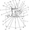
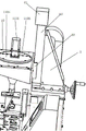
图1是本实用新型的结构示意图。Figure 1 is a schematic structural diagram of the present invention.
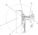
图2是图1中A的放大示意图。FIG. 2 is an enlarged schematic view of A in FIG. 1 .
图3是下料机构的搅拌电机安装示意图。Figure 3 is a schematic diagram of the installation of the stirring motor of the feeding mechanism.
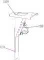
图4是环形料仓的结构示意图。Figure 4 is a schematic view of the structure of the annular silo.
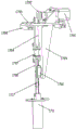
图5是下压机构的结构示意图。FIG. 5 is a schematic structural diagram of the pressing mechanism.
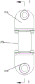
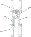
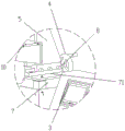
图6是缓冲组件的结构示意图。FIG. 6 is a schematic diagram of the structure of the buffer assembly.
图7是图6中B方向剖视图。FIG. 7 is a cross-sectional view in the direction B of FIG. 6 .
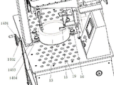
图8是模具的安装示意图。Figure 8 is a schematic diagram of the installation of the mold.
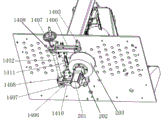
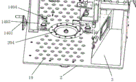
图9是对中机构的结构示意图。FIG. 9 is a schematic diagram of the structure of the centering mechanism.
图10是转动机构的结构示意图。FIG. 10 is a schematic structural diagram of a rotating mechanism.
图11是升降装置的安装示意图。Figure 11 is a schematic diagram of the installation of the lifting device.
图12是图1中C的放大示意图。FIG. 12 is an enlarged schematic view of C in FIG. 1 .
其中,1.机架,2.工作平台,3.控制器,4.移动转盘,5.移动滑块,6.升降装置,61.升降电机,62.第二升降滑块,63.升降螺杆,7.移动底座,71.移动滑轨,8.移动螺杆,9.下压支撑柱,901.升降滑轨,10.升降平台,101.横向滑轨,11. 下料机构,1101.搅拌电机,1102.下料联轴器,1103.下料连接法兰,1104.下料支盘,1105.仓盖,1106.料仓,1107.绞龙,1108.第一振动电机,1109.环形料仓,1110.第二振动电机,1111.出料管,12.第一升降滑块,13.模具,14.对中机构,1401.对中转盘,1402.对中螺杆,1403.对中板,1404.对中轴承,1405.对中直板,1406.对中连接板,1407.对中支座,1408.对中丝母,1410.对中滑块,1411.对中滑轨,15.刮刀,16.刮料支架,17.下压机构,1701.下压电机,1702.偏心轮,1704.下压连接板,1705.下压支板,1706.下压滑块,1707.缓冲组件,1708.下压滑动板,1709.下压固定板,1710.固定滑块,1711.压块,1712.上连接板,1713.上连接轴,1714.下连接管,1715.下连接板,1716.缓冲弹簧,1717.滑动滑轨,19.滚珠,20.转动机构,201.转动电机,202.转动联轴器,203.转动支座,204.转动盘。Among them, 1. Rack, 2. Working platform, 3. Controller, 4. Moving turntable, 5. Moving slider, 6. Lifting device, 61. Lifting motor, 62. Second lifting slider, 63. Lifting screw , 7. Mobile base, 71. Mobile slide, 8. Mobile screw, 9. Press support column, 901. Lifting slide, 10. Lifting platform, 101. Horizontal slide, 11. Unloading mechanism, 1101. Stirring Motor, 1102. Feeding coupling, 1103. Feeding connection flange, 1104. Feeding support plate, 1105. Silo cover, 1106. Silo, 1107. Auger, 1108. First vibration motor, 1109. Ring Silo, 1110. Second vibration motor, 1111. Discharge pipe, 12. First lifting slider, 13. Die, 14. Centering mechanism, 1401. Centering turntable, 1402. Centering screw, 1403. Centering Plate, 1404. Centering bearing, 1405. Centering straight plate, 1406. Centering connecting plate, 1407. Centering support, 1408. Centering nut, 1410. Centering slider, 1411. Centering slide, 15 . Scraper, 16. Scraper bracket, 17. Press down mechanism, 1701. Press down motor, 1702. Eccentric wheel, 1704. Press down connection plate, 1705. Press down support plate, 1706. Press down slider, 1707. Buffer assembly, 1708. Press down the sliding plate, 1709. Press down the fixed plate, 1710. Fixed the slider, 1711. Press block, 1712. Upper connecting plate, 1713. Upper connecting shaft, 1714. Lower connecting pipe, 1715. Lower connection Plate, 1716. Buffer spring, 1717. Sliding rail, 19. Ball, 20. Rotating mechanism, 201. Rotating motor, 202. Rotating coupling, 203. Rotating support, 204. Rotating disc.
具体实施方式Detailed ways
如附图1到12所示,一种半自动摊料机,包括机架1,所述机架1上方设有移动底座7,所述移动底座7上方设有移动滑块5,所述移动滑块5与移动底座7滑动配合,在移动滑块5一侧设有升降装置6,所述升降装置6一侧固定连接升降平台10,所述升降平台10上设有下料机构11,下料机构11的下料支盘1104与升降平台10固定连接,固定方式为螺栓连接,所述升降平台10远离升降装置6的一端滑动连接下压机构17,下压机构17的下压支板1705上设有下压滑块1706,升降平台10上设有横向滑轨101,下压滑块1706与横向滑轨101配合使用,所述下压机构17远离升降平台10的一侧设有下压支撑柱9,所述下压支撑柱9与升降平台10滑动连接,下压支撑柱9上设有升降滑轨901,升降平台10远离升降装置6的一端设有第一升降滑块12,所述第一升降滑块12固定在升降平台10下方,升降滑轨901与第一升降滑块12配合使用,在下料机构11的下端设有转动机构20,转动机构20的转动平台上方安置模具13,在转动平台周侧设有对中机构14。As shown in Figures 1 to 12, a semi-automatic spreader includes a
所述在移动底座7上设有移动滑轨71,移动滑块5与移动滑轨71滑动连接,所述移动滑轨71中部设有移动螺杆8,所述移动螺杆8与移动滑轨71铰接,在移动螺杆8一端设有移动转盘4,移动转盘4与移动螺杆8固定连接,所述移动滑块5通过螺纹连接移动螺杆8,移动螺杆8带动移动滑块5在移动滑轨71上移动,移动螺杆8与移动滑块5为滚珠丝杠副连接方式。The moving
所述下料机构11还包括搅拌电机1101、下料联轴器1102、仓盖1105、料仓1106和绞龙1107,所述仓盖1105与下料支盘1104铰接,在下料支盘1104上端中部通过下料连接法兰1103固定连接搅拌电机1101,下料支盘1104下端固定连接料仓1106,料仓1106内部安置绞龙1107,所述搅拌电机1101通过下料联轴器1102连接绞龙1107,在料仓1106的外壁设有振动电机,所述第一振动电机1108通过第一振动底座固定连接料仓1106,在料仓1106下方的出口端通过连接板固定连接环形料仓1109,所述环形料仓1109的外壁设有第二振动电机1110,所述第二振动电机1110通过第二振动底座连接环形料仓1109。The
所述环形料仓1109的横截面为Y型,环形料仓1109下方的出口端与模具13的弧度配合使用。The cross section of the
下压机构17还包括下压电机1701、偏心轮1702和缓冲组件1707,所述下压支板1705上端安置下压电机1701,下压电机1701的工作端连接偏心轮1702,在下压支板1705的下端设有下压连接板1704,所述下压连接板1704一端铰接偏心轮1702,下压连接板1704另一端铰接缓冲组件1707,所述缓冲组件1707下端铰接下压滑动板1708,所述下压滑动板1708下端铰接压块1711,所述下压连接板1704一侧设有下压固定板1709,所述下压固定板1709通过螺栓固定在下压支板1705的下端,在下压固定板1709一侧设有固定滑块1710,下压滑动板1708上设有滑动滑轨1717,所述下压滑动板1708通过滑动滑轨1717与下压固定板1709滑动连接。The
所述缓冲组件1707包括上连接板1712和下连接板1715,所述上连接板1712下端固定连接上连接轴1713,下连接板1715上端固定连接下连接管1714,所述上连接轴1713套接在下连接管1714中,在上连接板1712与下连接板1715之间固定连接缓冲弹簧1716。The
所述上连接板1712上端与下压连接板1704铰接,下连接板1715下端与下压滑动板1708铰接。The upper end of the upper connecting
所述升降装置6包括升降电机61、升降螺杆63和第二升降滑块62,所述升降电机61固定在移动滑块5上端,升降电机61的工作端通过联轴器连接升降螺杆63,所述升降螺杆63与移动滑块5铰接,第二升降滑块62与升降螺杆63通过滚珠丝杠副配合连接,第二升降滑块62与升降平台10固定连接。The
所述转动机构20包括转动电机201、转动盘204和转动支座203,所述转动盘204设置在机架1的工作平台2中部,即压板和环形料仓1109的出料管1111下方,转动盘204下端通过转动联轴器202连接转动电机201,所述转动电机201通过转动支座203固定在工作平台2的下方。The
所述对中机构14包括相对设置的对中板1403,所述对中板1403与工作平台2滑动配合,所述工作平台2下方设有对中连接板1406,所述对中连接板1406通过对中直板1405固定连接对中板1403,工作平台2上端设有对中滑槽,对中直板1405穿插在对中滑槽中,所述对中连接板1406固定连接对中丝母1408,所述对中丝母1408螺纹连接对中螺杆1402,所述对中螺杆1402通过对中支座1407铰接工作平台2,对中螺杆1402为正反丝杆,对中丝母1408与对中螺杆1402为滚珠丝杠副配合连接,所述对中连接板1406一侧固定连接对中滑块1410,对中滑块1410滑动连接对中滑轨1411,所述对中滑轨1411固定在工作平台2下方,在对中板1403两端铰接对中轴承1404,在对中螺杆1402一侧设有对中转盘1401,对中转盘1401固定连接对中螺杆1402。The centering
工作平台2上还设有控制器3,控制器3线连接下压电机1701、搅拌电机1101、升降电机61和转动电机201工作,控制器3为PLC或单片机控制器3,整个装置均匀由外部提供电源,控制器3连接电源,进而控制整个装置的工作,工作平台2上设有若干个滚珠19,便于模具13在工作平台2上移动,在模具13上方周侧设有刮板,所述刮板通过刮料支架16连接工作平台2,刮料支架16为L型,刮料支架16通过螺纹连接固定在工作平台2上。There is also a
本实用新型的工作过程如下:首先,将模具13放置在转动机构20的转动盘204上,手动转动对中转盘1401,对中转盘1401带动对中螺杆1402工作,对中螺杆1402上螺纹连接两个对中丝母1408,对中螺杆1402带动两个对中丝母1408做相反运动,对中丝母1408固定连接对中连接板1406,对中连接板1406固定连接对中直板1405,对中直板1405固定连接对中板1403,从而对中丝母1408带动对中板1403往转动盘204处移动,直到对中板1403上的对中轴承1404夹紧模具13为止,对中板1403为V型板或者弧形板,对中板1403上的对中轴承1404起到使模具13居中并夹紧的作用,完成对中操作,The working process of the present invention is as follows: first, the
控制器3启动升降电机61工作,升降电机61通过升降联轴器带动升降螺杆63,升降螺杆63带动第二升降滑块62上升或下降,第二升降滑块62带动升降平台10上升或下降,升降平台10上安装有下料机构11和下压机构17,升降平台10带动下料机构11和下压机构17的上升或下降,同时,第一升降滑块12沿下压支撑柱9上升或下降,加固升降平台10,防止上升或下降发生倾斜现象,用来调整下料机构11和下压机构17的位置,使压板和环形料仓1109的出料管1111在模具13中,出料管1111和压板均匀模具13配合使用,不同弧度的模具13配合使用不同的出料管1111和压板,若下料机构11和下压机构17没有与模具13同心,手动转动移动转盘4,移动转盘4带动移动螺杆8转动,移动螺杆8带动移动滑块5沿移动滑轨71滑动,移动滑块5带动升降平台10移动,直到下料机构11与模具13同心,然后手动推动下压支板1705,下压支板1705下方的下压滑块1706沿横向滑轨101滑动,从而下压支板1705带动整个下压机构17在升降平台10的横向导轨滑动,直到下压机构17与模具13同心为止;The
控制器3启动转动电机201、搅拌电机1101、下压电机1701、第一振动电机1108和第二振动电机1110同时工作,搅拌电机1101通过下料联轴器1102带动绞龙1107工作,绞龙1107将物料搅拌,第一振动电机1108对料仓1106进行振动,防止物料粘附在料仓1106内壁上,同时加快物料的搅拌,搅拌后的物料在重力作用下进入环形料仓1109,在第二振动电机1110和重力的作用下,物料通过出料管1111进而模具13中,转动电机201通过转动联轴器202带动转动盘204,转动盘204带动模具13转动,对中板1403上的对中轴承1404使模具13在旋转中,一直在在转动盘204中间,模具13的中心线与转动盘204的中心线始终保持重合,下压电机1701带动偏心轮1702转动,偏心轮1702带动下压连接板1704上下运动,下压连接板1704通过缓冲组件1707带动下压滑动板1708在滑动滑轨1717上上下移动,从而下压滑动板1708带动压板上下移动,压板对模具13中的物料进行间歇性压制,缓冲组件1707包括上连接板1712和下连接板1715,上连接板1712下端固定连接上连接轴1713,下连接板1715上端固定连接下连接管1714,上连接轴1713套接在下连接管1714中,在上连接板1712与下连接板1715之间固定连接缓冲弹簧1716,当上连接板1712受力时,缓冲弹簧1716会进行压缩防止硬性下压。The
以上所述的仅是本实用新型的优选实施方式,应当指出,对于本领域的技术人员来说,在不脱离本实用新型整体构思前提下,还可以作出若干改变和改进,这些也应该视为本实用新型的保护范围。The above are only the preferred embodiments of the present utility model. It should be pointed out that for those skilled in the art, some changes and improvements can be made without departing from the overall concept of the present utility model. These should also be regarded as The scope of protection of the utility model.
Claims (10)
Priority Applications (1)
| Application Number | Priority Date | Filing Date | Title |
|---|---|---|---|
| CN201922348894.4U CN211867523U (en) | 2019-12-24 | 2019-12-24 | Semi-automatic material spreading machine |
Applications Claiming Priority (1)
| Application Number | Priority Date | Filing Date | Title |
|---|---|---|---|
| CN201922348894.4U CN211867523U (en) | 2019-12-24 | 2019-12-24 | Semi-automatic material spreading machine |
Publications (1)
| Publication Number | Publication Date |
|---|---|
| CN211867523U true CN211867523U (en) | 2020-11-06 |
Family
ID=73262149
Family Applications (1)
| Application Number | Title | Priority Date | Filing Date |
|---|---|---|---|
| CN201922348894.4U Expired - Fee Related CN211867523U (en) | 2019-12-24 | 2019-12-24 | Semi-automatic material spreading machine |
Country Status (1)
| Country | Link |
|---|---|
| CN (1) | CN211867523U (en) |
Cited By (1)
| Publication number | Priority date | Publication date | Assignee | Title |
|---|---|---|---|---|
| CN113021202A (en) * | 2019-12-24 | 2021-06-25 | 郑州大华机电技术有限公司 | Semi-automatic material spreading machine |
-
2019
- 2019-12-24 CN CN201922348894.4U patent/CN211867523U/en not_active Expired - Fee Related
Cited By (2)
| Publication number | Priority date | Publication date | Assignee | Title |
|---|---|---|---|---|
| CN113021202A (en) * | 2019-12-24 | 2021-06-25 | 郑州大华机电技术有限公司 | Semi-automatic material spreading machine |
| CN113021202B (en) * | 2019-12-24 | 2025-05-09 | 郑州大华机电技术有限公司 | Semi-automatic material spreading machine |
Similar Documents
| Publication | Publication Date | Title |
|---|---|---|
| CN113771193A (en) | Novel brick making machine for bauxite homogenized material refractory bricks | |
| CN105598864B (en) | Prepared by a kind of extra hard material grinding wheel throws stand material device with automatic | |
| CN105835400B (en) | Full automatic screw quantifying feed briquetting press | |
| CN205415977U (en) | Improved generation block forming machine | |
| CN205114549U (en) | Automatic powder pouring equipment | |
| CN211867525U (en) | Semi-automatic material spreading machine discharging mechanism | |
| CN106672468A (en) | A stirring type solid powder hopper anti-blocking device | |
| CN105619573A (en) | Full-automatic hydraulic brick press of cylindrical refractory bricks and brick pressing process | |
| CN211867524U (en) | Semi-automatic spreading machine pushing mechanism | |
| CN113021202B (en) | Semi-automatic material spreading machine | |
| CN109774230B (en) | An automatic feeding press | |
| CN219324292U (en) | Feeding structure of grinding machine | |
| CN208245737U (en) | A kind of resin sand process units | |
| CN215709566U (en) | Plastics production raw materials conveyer | |
| CN105108903B (en) | A kind of cement mortar agitating device automatic blanking transmission mechanism | |
| CN205466697U (en) | Cylindric is able to bear or endure homocline ware and hydraulic automatic tile press for firebrick | |
| CN108860772B (en) | A quantitative bagging equipment | |
| CN223254122U (en) | Rotary liftable concrete discharging device | |
| CN219236283U (en) | Feeding mechanism of bi-component annular part preforming device | |
| CN220998011U (en) | Raw material feeding device for feed production | |
| CN221848648U (en) | A continuous powder filling device for molybdenum bar production | |
| CN219566854U (en) | a feeding device | |
| CN221274605U (en) | Automatic lifting unloader convenient to installation | |
| CN224029976U (en) | Screw conveying type scrap iron supply device | |
| CN210709697U (en) | A feeding device for a feeder |
Legal Events
| Date | Code | Title | Description |
|---|---|---|---|
| GR01 | Patent grant | ||
| GR01 | Patent grant | ||
| CF01 | Termination of patent right due to non-payment of annual fee | ||
| CF01 | Termination of patent right due to non-payment of annual fee |
Granted publication date: 20201106 |