CN211855442U - Hydraulic engineering gate area quality of water yield check out test set - Google Patents
Hydraulic engineering gate area quality of water yield check out test set Download PDFInfo
- Publication number
- CN211855442U CN211855442U CN202020448881.4U CN202020448881U CN211855442U CN 211855442 U CN211855442 U CN 211855442U CN 202020448881 U CN202020448881 U CN 202020448881U CN 211855442 U CN211855442 U CN 211855442U
- Authority
- CN
- China
- Prior art keywords
- gate
- water
- sliding plate
- rod
- sleeve
- Prior art date
- Legal status (The legal status is an assumption and is not a legal conclusion. Google has not performed a legal analysis and makes no representation as to the accuracy of the status listed.)
- Withdrawn - After Issue
Links
- XLYOFNOQVPJJNP-UHFFFAOYSA-N water Substances O XLYOFNOQVPJJNP-UHFFFAOYSA-N 0.000 title claims abstract description 84
- 238000012360 testing method Methods 0.000 title claims abstract description 10
- 238000001514 detection method Methods 0.000 claims abstract description 28
- 230000033001 locomotion Effects 0.000 description 5
- 238000005070 sampling Methods 0.000 description 5
- 238000005086 pumping Methods 0.000 description 4
- 238000001914 filtration Methods 0.000 description 3
- 239000013049 sediment Substances 0.000 description 3
- 230000005540 biological transmission Effects 0.000 description 2
- 238000010586 diagram Methods 0.000 description 1
- 230000003028 elevating effect Effects 0.000 description 1
- 238000007689 inspection Methods 0.000 description 1
- 230000002262 irrigation Effects 0.000 description 1
- 238000003973 irrigation Methods 0.000 description 1
- 238000000034 method Methods 0.000 description 1
- 238000012372 quality testing Methods 0.000 description 1
Images


Landscapes
- Barrages (AREA)
Abstract
The utility model belongs to the technical field of hydraulic engineering equipment, especially, be a hydraulic engineering gate area quality of water yield check out test set, be mostly fixed mounting to current gate area quality of water yield check out test set and be difficult to remove and lead to the unsafe problem of testing result, the scheme is put forward now, and it includes first gate pillar, second gate pillar and gate body, one side top fixed mounting that first gate pillar and second gate pillar are close to each other has same gate support frame, and gate support frame top fixed mounting has the gate to open and close the ware, and the gate is opened and close the one end of the equal fixedly connected with lifter in ware bottom both sides, the other end of two lifters all with gate body top fixed connection. The utility model has the advantages of reasonable design, can detect the gate region water of different positions through driving horizontal and vertical slip of detection seat, improve the accuracy that detects the structure, the reliability is high.
Description
Technical Field
The utility model relates to a hydraulic engineering equipment technical field especially relates to a hydraulic engineering gate area quality of water yield check out test set.
Background
The sluice is used as an important water conservancy infrastructure and has important functions in shipping, irrigation, water supply, flood control, hydroelectric generation, river flow regulation, water environment improvement and the like. Main quality of water and water level height and discharge near often inspection gate in hydraulic engineering, but present water intaking mode all is artifical water intaking, and the water intaking in-process meets accident easily to can not in time detect water level change and rivers speed. The existing water quality and water quantity detection equipment for the water conservancy project gate area comprises a gate hoist, a water sample sampling device, a gate support frame and a gate frame, wherein the gate hoist is arranged above the gate support frame, a wireless controller is arranged above the gate hoist, an oil pump motor is arranged in the gate hoist, the gate support frame is arranged on the gate frame, a gate is arranged below the gate support frame, the gate is connected with the gate hoist through a lifting rod, the number of the lifting rods is two, the water sample sampling device is arranged on the gate support frame, a water pumping pipe is arranged below the water sample sampling device, a water sample collector is arranged at the bottom end of the water pumping pipe, a sediment filtering and metering device is arranged below the water sample collector, the water sample sampling device, the water pumping pipe, the collector and the sediment filtering and metering device are respectively provided with two devices, and two water sample sampling devices, a water pumping pipe, a water sample collector and a sediment filtering and metering device are respectively arranged on the frames at the two sides of the gate frame.
However, the device can only detect the water quality of the gate area at the same position, cannot detect the water at different depths and different horizontal positions at the same vertical position, and is inaccurate in detection, so that the device for detecting the water quality and the water quantity of the gate area of the hydraulic engineering is provided for solving the problems.
SUMMERY OF THE UTILITY MODEL
The utility model aims at solving the current regional quality of water yield check out test set of gate and mostly being difficult to remove and leading to the unsafe shortcoming of testing result for fixed mounting, and the regional quality of water yield check out test set of hydraulic engineering gate that proposes.
In order to achieve the above purpose, the utility model adopts the following technical scheme:
a water quality and water quantity detection device for a water conservancy project gate area comprises a first gate column, a second gate column and a gate body, wherein the top of one side, close to each other, of the first gate column and the second gate column is fixedly provided with the same gate support frame, the top of the gate support frame is fixedly provided with a gate opening and closing device, two sides of the bottom of the gate opening and closing device are fixedly connected with one end of a lifting rod, the other ends of the two lifting rods are fixedly connected with the top of the gate body, one side, close to each other, of the first gate column and the second gate column is respectively provided with a first sliding groove and a second sliding groove, a first sliding plate and a second sliding plate are respectively arranged in the first sliding groove and the second sliding groove in a sliding manner, one side, close to each other, of the first sliding plate and the second sliding plate is rotatably provided with the same lead screw, the outer side of the lead screw is, first gate stylobate and second gate stylobate top respectively fixed mounting have first motor and second motor, and second motor output shaft extends to in the second spout and fixed mounting has square pole, vertical groove has been seted up to second slide bottom, has seted up the mounting hole on the vertical groove top inner wall, and the mounting hole rotates internally and installs the sleeve, and the sleeve slip cap is established in the square pole outside, and the equal fixed mounting of one end that sleeve and lead screw are close to each other has bevel gear, and two bevel gear mesh mutually.
Preferably, one side fixedly connected with same connecting rod that first slide and second slide are close to each other, it establishes in the connecting rod outside to detect the seat slip cap, leads and spacing to detecting the seat.
Preferably, the first motor output shaft extends into the first chute and is fixedly provided with a threaded rod, the first sliding plate is sleeved on the outer side of the threaded rod through a threaded sleeve, and the first sliding plate is driven by the first motor to move up and down.
Preferably, the bottom end of the square rod is fixedly connected with a positioning shaft, and the second sliding plate is rotatably sleeved on the outer side of the positioning shaft to position the square rod.
Preferably, the same guide rod is fixedly connected between the inner wall of the bottom of the second sliding groove and the inner wall of the bottom of the second sliding groove, and the second sliding plate is slidably sleeved on the outer side of the guide rod to guide and limit the second sliding plate.
Preferably, the sleeve outside is fixedly sleeved with a limiting shaft sleeve, and the limiting shaft sleeve is movably connected with the top of the second sliding plate to limit the sleeve.
In the utility model, the water quality and water quantity detection equipment for the water conservancy project gate area controls two lifting rods through a gate opening and closing device to open a gate body, detects water quality through a water quality detector, detects water quantity through a flowmeter, and can drive a first motor by opening the first motor, a first motor output shaft drives a threaded rod to rotate, the threaded rod drives a first sliding plate to do lifting motion through the thread fit with the first sliding plate, and the first sliding plate drives a detection seat to do lifting motion through a connecting rod, so that the water in the gate body area with different depths at the same vertical position is detected;
in the utility model, the water quality and water quantity detection equipment for the water conservancy project gate area is characterized in that when a second motor is started, an output shaft of the second motor drives a square rod to rotate, the square rod drives a sleeve to rotate, the sleeve drives a lead screw to rotate through transmission between two bevel gears, and the lead screw drives a detection seat to horizontally move left and right through screw thread matching with the detection seat, so that water with the same depth and different horizontal positions is detected, and the accuracy of a detection result is improved;
the utility model has the advantages of reasonable design, can detect the gate region water of different positions through driving horizontal and vertical slip of detection seat, improve the accuracy that detects the structure, the reliability is high.
Drawings
Fig. 1 is a schematic structural view of a water quality and water quantity detection device in a gate area of a hydraulic engineering provided by the utility model;
fig. 2 is a schematic structural view of a part a of a water quality and water quantity detection device in a gate area of a hydraulic engineering provided by the utility model;
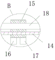
fig. 3 is a schematic structural diagram of part B of a water quality and water quantity detection device in a gate area of a hydraulic engineering.
In the figure: 1. a first gate pillar; 2. a second gate pillar; 3. a gate body; 4. a gate support frame; 5. a gate opener; 6. a first motor; 7. a second motor; 8. a first chute; 9. a first slide plate; 10. a threaded rod; 11. a second chute; 12. a second slide plate; 13. a square rod; 14. a screw rod; 15. a detection seat; 16. a water quality detector; 17. a flow meter; 18. a connecting rod; 19. a vertical groove; 20. a sleeve; 21. a guide bar; 22. a limiting shaft sleeve; 23. positioning the shaft; 24. a lifting rod.
Detailed Description
The technical solutions in the embodiments of the present invention will be described clearly and completely with reference to the accompanying drawings in the embodiments of the present invention, and it is obvious that the described embodiments are only some embodiments of the present invention, not all embodiments.
Referring to fig. 1-3, a water quality and water quantity detection device for a gate area of a hydraulic engineering, comprising a first gate pillar 1, a second gate pillar 2 and a gate body 3, wherein the top of one side, close to each other, of the first gate pillar 1 and the second gate pillar 2 is fixedly provided with a same gate support frame 4, the top of the gate support frame 4 is fixedly provided with a gate opener 5, two sides of the bottom of the gate opener 5 are fixedly connected with one end of a lifting rod 24, the other ends of the two lifting rods 24 are fixedly connected with the top of the gate body 3, one side, close to each other, of the first gate pillar 1 and the second gate pillar 2 is respectively provided with a first chute 8 and a second chute 11, the first chute 8 and the second chute 11 are respectively provided with a first sliding plate 9 and a second sliding plate 12 in a sliding manner, one side, close to each other, of the first sliding plate 9 and the second sliding plate 12 is rotatably, screw 14 outside thread bush is equipped with detects seat 15, detect 15 bottom both sides of seat respectively fixed mounting have water quality testing ware 16 and flowmeter 17, first gate pillar 1 and 2 tops of second gate pillar fixed mounting have first motor 6 and second motor 7 respectively, second motor 7 output shaft extends to in the second spout 11 and fixed mounting has square pole 13, vertical groove 19 has been seted up to second slide 12 bottom, the mounting hole has been seted up on the inner wall at vertical groove 19 top, sleeve 20 is installed in the mounting hole rotation, sleeve 20 slip cap is established in the square pole 13 outside, the equal fixed mounting of one end that sleeve 20 and screw 14 are close to each other has bevel gear, two bevel gear mesh mutually.
The utility model discloses in, the same connecting rod 18 of one side fixedly connected with that first slide 9 and second slide 12 are close to each other, detect the 15 slip covers of seat and establish in the 18 outsides of connecting rod, lead and spacing to detecting seat 15.
The utility model discloses in, 6 output shafts of first motor extend to in the first spout 8 and fixed mounting have threaded rod 10, and 9 threaded sleeves of first slide are established in the threaded rod 10 outside, drive first slide 9 through first motor 6 and are elevating movement.
The utility model discloses in, square pole 13 bottom fixedly connected with location axle 23, second slide 12 rotate the cover and establish in the location axle 23 outside, fix a position square pole 13.
The utility model discloses in, the same guide bar 21 of fixedly connected with between 11 bottom inner walls of second spout and the bottom inner wall, second slide 12 slip cap is established in the guide bar 21 outside, leads and spacing second slide 12.
The utility model discloses in, the fixed cover in the sleeve 20 outside is equipped with spacing axle sleeve 22, and spacing axle sleeve 22 carries on spacingly with second slide 12 top swing joint to sleeve 20.
In the utility model, when in use, two lifting rods 24 are controlled by a gate opening and closing device 5 to open a gate body 3, water quality is detected by a water quality detector 16, water quantity is detected by a flowmeter 17, and a first motor 6 can be started, an output shaft of the first motor 6 drives a threaded rod 10 to rotate, the threaded rod 10 drives a first sliding plate 9 to do lifting motion through the thread matching with the first sliding plate 9, the first sliding plate 9 drives a detection seat 15 to do lifting motion through a connecting rod 18, thereby detecting water in the region of the gate body 3 with different depths at the same vertical position, and by starting a second motor 7, an output shaft of the second motor 7 drives a square rod 13 to rotate, the square rod 13 drives a sleeve 20 to rotate, the sleeve 20 drives a screw rod 14 to rotate through transmission between two bevel gears, the screw rod 14 drives the detection seat 15 to horizontally move through the thread matching with the detection seat 15, therefore, the water at different horizontal positions with the same depth is detected, and the accuracy of the detection result is improved.
Claims (6)
1. A water quality and water quantity detection device for a water conservancy project gate area comprises a first gate column (1), a second gate column (2) and a gate body (3), and is characterized in that the top of one side, close to each other, of the first gate column (1) and the second gate column (2) is fixedly provided with the same gate support frame (4), the top of the gate support frame (4) is fixedly provided with a gate opening and closing device (5), two sides of the bottom of the gate opening and closing device (5) are fixedly connected with one end of a lifting rod (24), the other ends of the two lifting rods (24) are fixedly connected with the top of the gate body (3), one side, close to each other, of the first gate column (1) and the second gate column (2) is respectively provided with a first sliding chute (8) and a second sliding chute (11), a first sliding plate (9) and a second sliding plate (12) are respectively and slidably arranged in the first sliding chute (8) and the second sliding chute (11), one side of the first sliding plate (9) and the second sliding plate (12) which are close to each other is rotatably provided with the same screw rod (14), the outer side of the screw rod (14) is provided with a detection seat (15) in a threaded sleeve manner, two sides of the bottom of the detection seat (15) are respectively and fixedly provided with a water quality detector (16) and a flowmeter (17), the tops of the first gate pillar (1) and the second gate pillar (2) are respectively and fixedly provided with a first motor (6) and a second motor (7), an output shaft of the second motor (7) extends into the second sliding chute (11) and is fixedly provided with a square rod (13), the bottom of the second sliding plate (12) is provided with a vertical groove (19), the inner wall of the top of the vertical groove (19) is provided with a mounting hole, a sleeve (20) is rotatably arranged in the mounting hole, the sleeve (20) is sleeved outside the square rod (13) in a sliding manner, and one, the two bevel gears are meshed.
2. The water quality and water quantity detection equipment for the water conservancy project gate area according to claim 1, wherein one side, close to each other, of the first sliding plate (9) and the second sliding plate (12) is fixedly connected with the same connecting rod (18), and the detection seat (15) is sleeved on the outer side of the connecting rod (18) in a sliding manner.
3. The water conservancy project gate area quality of water yield check out test set of claim 1, characterized in that, first motor (6) output shaft extends to in first spout (8) and fixed mounting has threaded rod (10), first slide (9) threaded sleeve is established in the threaded rod (10) outside.
4. The water quality and water quantity detection equipment for the water conservancy project gate area according to claim 1, wherein a positioning shaft (23) is fixedly connected to the bottom end of the square rod (13), and the second sliding plate (12) is rotatably sleeved on the outer side of the positioning shaft (23).
5. The water quality and water quantity detection equipment for the water conservancy project gate area is characterized in that the same guide rod (21) is fixedly connected between the inner wall of the bottom of the second sliding chute (11) and the inner wall of the bottom of the second sliding chute, and the second sliding plate (12) is sleeved on the outer side of the guide rod (21) in a sliding manner.
6. The water quality and water quantity detection equipment for the water conservancy project gate area according to claim 1, wherein a limiting shaft sleeve (22) is fixedly sleeved on the outer side of the sleeve (20), and the limiting shaft sleeve (22) is movably connected with the top of the second sliding plate (12).
Priority Applications (1)
| Application Number | Priority Date | Filing Date | Title |
|---|---|---|---|
| CN202020448881.4U CN211855442U (en) | 2020-03-31 | 2020-03-31 | Hydraulic engineering gate area quality of water yield check out test set |
Applications Claiming Priority (1)
| Application Number | Priority Date | Filing Date | Title |
|---|---|---|---|
| CN202020448881.4U CN211855442U (en) | 2020-03-31 | 2020-03-31 | Hydraulic engineering gate area quality of water yield check out test set |
Publications (1)
| Publication Number | Publication Date |
|---|---|
| CN211855442U true CN211855442U (en) | 2020-11-03 |
Family
ID=73143508
Family Applications (1)
| Application Number | Title | Priority Date | Filing Date |
|---|---|---|---|
| CN202020448881.4U Withdrawn - After Issue CN211855442U (en) | 2020-03-31 | 2020-03-31 | Hydraulic engineering gate area quality of water yield check out test set |
Country Status (1)
| Country | Link |
|---|---|
| CN (1) | CN211855442U (en) |
Cited By (1)
| Publication number | Priority date | Publication date | Assignee | Title |
|---|---|---|---|---|
| CN118687768A (en) * | 2024-07-17 | 2024-09-24 | 山东黄河河务局供水局 | A sluice water leakage and seepage detection device and detection method |
-
2020
- 2020-03-31 CN CN202020448881.4U patent/CN211855442U/en not_active Withdrawn - After Issue
Cited By (2)
| Publication number | Priority date | Publication date | Assignee | Title |
|---|---|---|---|---|
| CN118687768A (en) * | 2024-07-17 | 2024-09-24 | 山东黄河河务局供水局 | A sluice water leakage and seepage detection device and detection method |
| CN118687768B (en) * | 2024-07-17 | 2024-11-22 | 山东黄河河务局供水局 | Water gate leakage and seepage amount detection device and detection method |
Similar Documents
| Publication | Publication Date | Title |
|---|---|---|
| CN214952428U (en) | Water sampling device for environmental detection | |
| CN210529654U (en) | River course floater cleaning device | |
| CN102505676B (en) | Hydraulic driving system of hydraulic-driven ship lift | |
| CN206157886U (en) | Gear formula automatic control intercepting device | |
| CN114518262A (en) | Sampling device and sampling method for aviation kerosene storage tank | |
| CN219195856U (en) | River channel sluice device for hydraulic engineering | |
| CN218492441U (en) | Water sluicegate equipment | |
| CN117030961A (en) | Portable coastal zone water quality monitoring device | |
| CN113777266B (en) | Fixed deep water quality monitoring equipment and monitoring method thereof | |
| CN215414535U (en) | Water intake device for water environmental engineering detection | |
| CN108362912A (en) | Novel current meter calibrating installation and its calibration method | |
| CN211875544U (en) | Quick adjusting device of beam-pumping unit belt | |
| CN219776682U (en) | River mud degree of depth detection device | |
| CN215573165U (en) | Hydrology flow measuring device | |
| CN112179710A (en) | Hydrology information acquisition device to river silt content | |
| CN207846355U (en) | A kind of gate detection device for being convenient for detection gatage and stroke | |
| CN111926874A (en) | Canal bottom sludge cleaning machine and method for hydraulic engineering | |
| CN219200940U (en) | Sediment detection device | |
| CN214224653U (en) | Water quality monitoring sampling device based on environmental protection | |
| CN214750233U (en) | Water quality treatment monitoring device | |
| CN118687768A (en) | A sluice water leakage and seepage detection device and detection method | |
| CN213121237U (en) | A submersible pump for sewage treatment | |
| CN220057833U (en) | Spiral push-pull rod type intelligent gate | |
| CN207688962U (en) | A kind of oil-water level measuring apparatus | |
| CN111929108A (en) | Submersible pump for sewage treatment and application of submersible pump for water quality upgrading |
Legal Events
| Date | Code | Title | Description |
|---|---|---|---|
| GR01 | Patent grant | ||
| GR01 | Patent grant | ||
| AV01 | Patent right actively abandoned | ||
| AV01 | Patent right actively abandoned | ||
| AV01 | Patent right actively abandoned |
Granted publication date: 20201103 Effective date of abandoning: 20210118 |
|
| AV01 | Patent right actively abandoned |
Granted publication date: 20201103 Effective date of abandoning: 20210118 |