CN211853846U - Intelligent self-adjusting solar street lamp - Google Patents
Intelligent self-adjusting solar street lamp Download PDFInfo
- Publication number
- CN211853846U CN211853846U CN202021012117.9U CN202021012117U CN211853846U CN 211853846 U CN211853846 U CN 211853846U CN 202021012117 U CN202021012117 U CN 202021012117U CN 211853846 U CN211853846 U CN 211853846U
- Authority
- CN
- China
- Prior art keywords
- street lamp
- bevel gear
- solar
- rotating shaft
- mounting plate
- Prior art date
- Legal status (The legal status is an assumption and is not a legal conclusion. Google has not performed a legal analysis and makes no representation as to the accuracy of the status listed.)
- Expired - Fee Related
Links
Images

Classifications
-
- Y—GENERAL TAGGING OF NEW TECHNOLOGICAL DEVELOPMENTS; GENERAL TAGGING OF CROSS-SECTIONAL TECHNOLOGIES SPANNING OVER SEVERAL SECTIONS OF THE IPC; TECHNICAL SUBJECTS COVERED BY FORMER USPC CROSS-REFERENCE ART COLLECTIONS [XRACs] AND DIGESTS
- Y02—TECHNOLOGIES OR APPLICATIONS FOR MITIGATION OR ADAPTATION AGAINST CLIMATE CHANGE
- Y02B—CLIMATE CHANGE MITIGATION TECHNOLOGIES RELATED TO BUILDINGS, e.g. HOUSING, HOUSE APPLIANCES OR RELATED END-USER APPLICATIONS
- Y02B20/00—Energy efficient lighting technologies, e.g. halogen lamps or gas discharge lamps
- Y02B20/72—Energy efficient lighting technologies, e.g. halogen lamps or gas discharge lamps in street lighting
-
- Y—GENERAL TAGGING OF NEW TECHNOLOGICAL DEVELOPMENTS; GENERAL TAGGING OF CROSS-SECTIONAL TECHNOLOGIES SPANNING OVER SEVERAL SECTIONS OF THE IPC; TECHNICAL SUBJECTS COVERED BY FORMER USPC CROSS-REFERENCE ART COLLECTIONS [XRACs] AND DIGESTS
- Y02—TECHNOLOGIES OR APPLICATIONS FOR MITIGATION OR ADAPTATION AGAINST CLIMATE CHANGE
- Y02E—REDUCTION OF GREENHOUSE GAS [GHG] EMISSIONS, RELATED TO ENERGY GENERATION, TRANSMISSION OR DISTRIBUTION
- Y02E10/00—Energy generation through renewable energy sources
- Y02E10/50—Photovoltaic [PV] energy
Landscapes
- Non-Portable Lighting Devices Or Systems Thereof (AREA)
Abstract
本实用新型公开了一种智能型自调节太阳能路灯,包括固定设置于地面上的底座,底座上设置有路灯杆,路灯杆上端外侧固定套设有安装套,安装套一侧固定设置有路灯组件,安装套另一侧固定设置有传动箱,传动箱内部设置有驱动电机,驱动电机的驱动轴与可转动的设置于路灯杆内部的第一伞齿轮传动连接;路灯杆的上端可转动的设置有转轴,转轴的下端设置有与第一伞齿轮相啮合的第二伞齿轮,转轴上部固定设置有安装板,安装板一端铰接设置有太阳能电池板,太阳能电池板底部中央与所述安装板另一端之间设置有电动伸缩杆。本实用新型的太阳能电池板能够适应不同时刻的太阳位置和太阳光照射角度,提高了太阳能路灯对太阳能的利用效率。

The utility model discloses an intelligent self-adjusting solar street lamp, which comprises a base fixedly arranged on the ground, a street lamp pole is arranged on the base, an installation sleeve is fixed on the outer side of the upper end of the street lamp pole, and a street lamp assembly is fixedly arranged on one side of the installation sleeve , a transmission box is fixedly arranged on the other side of the installation sleeve, a drive motor is arranged inside the transmission box, and the drive shaft of the drive motor is connected with a rotatable first bevel gear arranged inside the street lamp pole; the upper end of the street lamp pole is rotatably arranged There is a rotating shaft, the lower end of the rotating shaft is provided with a second bevel gear meshing with the first bevel gear, a mounting plate is fixedly arranged on the upper part of the rotating shaft, and one end of the mounting plate is hinged with a solar panel, and the center of the bottom of the solar panel is separate from the mounting plate. An electric telescopic rod is arranged between one end. The solar cell panel of the utility model can adapt to the position of the sun and the irradiation angle of the sunlight at different times, thereby improving the utilization efficiency of the solar energy by the solar street lamp.
Description
技术领域technical field
本实用新型涉及太阳能路灯技术领域,尤其涉及一种智能型自调节太阳能路灯。The utility model relates to the technical field of solar street lamps, in particular to an intelligent self-adjusting solar street lamp.
背景技术Background technique
随着科技的发展以及节能减排意识的提升,太阳能路灯在许多地方开始普及。太阳能路灯通过采用晶体硅太阳能电池板供电,并采用相应的蓄电池储存电能,从而代替传统的公用电力照明的路灯,其具有节能环保和经济实用等优点。现有的太阳能路灯的太阳能电池板均为固定式安装,其位置和角度在安装完成后保持不变,然而在一天中太阳的位置和太阳光的照射角度是会发生变化的,这就导致太能能电池板在某些时刻不能很好的吸收太阳光,因此研制一种智能型自调节太阳能路灯很有必要。With the development of science and technology and the improvement of awareness of energy saving and emission reduction, solar street lights have become popular in many places. Solar street lights are powered by crystalline silicon solar panels, and corresponding batteries are used to store electrical energy, thereby replacing traditional street lights for public power lighting. It has the advantages of energy saving, environmental protection, economy and practicality. The solar panels of the existing solar street lights are all fixedly installed, and their positions and angles remain unchanged after the installation is completed. Energy panels cannot absorb sunlight well at certain times, so it is necessary to develop an intelligent self-adjusting solar street light.
实用新型内容Utility model content
本实用新型的目的是提供一种智能型自调节太阳能路灯,解决上述背景技术中提到的技术问题。The purpose of this utility model is to provide an intelligent self-adjusting solar street light, which solves the technical problems mentioned in the above background art.
为解决上述技术问题,本实用新型采用如下技术方案:In order to solve the above-mentioned technical problems, the utility model adopts the following technical solutions:
本实用新型一种智能型自调节太阳能路灯,包括固定设置于地面上的底座,所述底座上设置有路灯杆,所述路灯杆的上半部为空心结构且其上端的外侧固定套设有安装套,所述安装套的一侧固定设置有路灯组件,所述安装套的另一侧固定设置有传动箱,所述传动箱的内部设置有驱动电机,所述驱动电机的驱动轴与可转动的设置于所述路灯杆内部的第一伞齿轮传动连接;所述路灯杆的上端可转动的设置有转轴,所述转轴的下端设置有与所述第一伞齿轮相啮合的第二伞齿轮,所述转轴的上部固定设置有安装板,所述安装板的一端铰接设置有太阳能电池板,所述太阳能电池板的底部中央与所述安装板的另一端之间设置有电动伸缩杆。The utility model relates to an intelligent self-adjusting solar street lamp, comprising a base fixedly arranged on the ground, a street lamp pole is arranged on the base, the upper half of the street lamp pole is a hollow structure, and the outer side of the upper end is fixedly sleeved with a lamp pole. An installation sleeve, one side of the installation sleeve is fixedly provided with a street lamp assembly, the other side of the installation sleeve is fixedly installed with a transmission box, and a drive motor is arranged inside the transmission box, and the drive shaft of the drive motor is connected with the adjustable A first bevel gear that is rotatably arranged inside the street light pole is connected by transmission; the upper end of the street light pole is rotatably provided with a rotating shaft, and the lower end of the rotating shaft is provided with a second bevel gear that meshes with the first bevel gear Gear, a mounting plate is fixed on the upper part of the rotating shaft, one end of the mounting plate is hinged with a solar panel, and an electric telescopic rod is arranged between the bottom center of the solar panel and the other end of the mounting plate.
进一步的,所述驱动电机的驱动轴与设置于所述传动箱内的减速机的输入端相连接,所述减速机的输出端与第一齿轮轴的一端相连接,所述第一齿轮轴的另一端贯穿所述安装套和所述路灯杆的周壁延伸至所述路灯杆的内部,所述第一伞齿轮设置于所述第一齿轮轴位于所述路灯杆内部的一端。Further, the drive shaft of the drive motor is connected with the input end of the reducer arranged in the transmission case, and the output end of the reducer is connected with one end of the first gear shaft, the first gear shaft. The other end extends through the mounting sleeve and the peripheral wall of the street light pole to the inside of the street light pole, and the first bevel gear is arranged on one end of the first gear shaft inside the street light pole.
进一步的,所述转轴的下端固定设置有第二齿轮轴,所述第二伞齿轮设置于所述第二齿轮轴的下端。Further, a second gear shaft is fixedly arranged at the lower end of the rotating shaft, and the second bevel gear is arranged at the lower end of the second gear shaft.
与现有技术相比,本实用新型的有益技术效果:Compared with the prior art, the beneficial technical effects of the present utility model:
本实用新型的驱动电机通过第一伞齿轮和第二伞齿轮的传动作用可以驱动所述安装板旋转,实现对太阳能电池板方向的调节;电动伸缩杆的伸缩运动实现了对太阳能电池板角度的调整,从而本实用新型的太阳能电池板能够适应不同时刻的太阳位置和太阳光照射角度,提高了太阳能路灯对太阳能的利用效率。The drive motor of the utility model can drive the mounting plate to rotate through the transmission action of the first bevel gear and the second bevel gear, so as to realize the adjustment of the direction of the solar cell panel; the telescopic movement of the electric telescopic rod realizes the adjustment of the angle of the solar cell panel. Therefore, the solar cell panel of the present invention can adapt to the position of the sun and the irradiation angle of the sun light at different times, thereby improving the utilization efficiency of the solar energy by the solar street lamp.
附图说明Description of drawings
下面结合附图说明对本实用新型作进一步说明。The present utility model will be further described below in conjunction with the accompanying drawings.
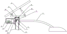
图1为本实用新型结构示意图;Fig. 1 is the structural representation of the utility model;
图2为本实用新型上部结构剖视图;2 is a cross-sectional view of the upper structure of the utility model;
附图标记说明:1、底座;2、路灯杆;3、安装套;4、路灯组件;5、传动箱;6、驱动电机;7、第一伞齿轮;8、转轴;9、第二伞齿轮;10、安装板;11、太阳能电池板;12、电动伸缩杆;13、减速机;14、第一齿轮轴;15、第二齿轮轴。Description of reference numerals: 1, base; 2, street lamp pole; 3, installation sleeve; 4, street lamp assembly; 5, transmission box; 6, drive motor; 7, first bevel gear; 8, rotating shaft; 9, second umbrella gear; 10, mounting plate; 11, solar panel; 12, electric telescopic rod; 13, reducer; 14, first gear shaft; 15, second gear shaft.
具体实施方式Detailed ways
如图1-图2所示,一种智能型自调节太阳能路灯,包括固定设置于地面上的底座1,所述底座1上设置有路灯杆2。所述路灯杆2的上半部为空心结构且其上端的外侧固定套设有安装套3,所述安装套3套装在所述路灯杆2的上端后通过多个螺栓使其与路灯杆固定连接,所述安装套3的一侧固定安装有路灯组件4。As shown in FIGS. 1-2 , an intelligent self-adjusting solar street light includes a base 1 fixedly arranged on the ground, and a
所述安装套3的另一侧固定设置有传动箱5,所述传动箱5的内部安装有驱动电机6,所述驱动电机6的驱动轴与可转动的安装于所述路灯杆2内部的第一伞齿轮7传动连接。具体的,所述传动箱5内安装有减速机13,所述驱动电机6的驱动轴与所述减速机13的输入端相连接。所述减速机13的输出端与第一齿轮轴14的一端相连接,所述第一齿轮轴14的另一端贯穿所述安装套3和所述路灯杆2的周壁延伸至所述路灯杆2的内部,并且所述第一齿轮轴14与所述安装套3和所述路灯杆2的周壁转动配合,所述第一伞齿轮7安装于所述第一齿轮轴14位于所述路灯杆2内部的一端。The other side of the
所述路灯杆2的上端可转动的安装有转轴8,所述转轴8的下端设置有与所述第一伞齿轮7相啮合的第二伞齿轮9,具体的,所述转轴8的下端固定设置有与其同轴线的第二齿轮轴15,所述第二伞齿轮9安装于所述第二齿轮轴15的下端。所述转轴8的上部固定设置有安装板10,所述安装板10的一端铰接安装有太阳能电池板11。所述太阳能电池板11的底部中央与所述安装板10的另一端之间设置有电动伸缩杆12,所述电动伸缩杆12的主体与所述安装板10的另一端铰接连接,所述电动伸缩杆12的伸缩端与所述太阳能电池板11的底部中央铰接连接。A rotating
本实用新型还包括可编程逻辑控制器(PLC),所述驱动电机与所述电动伸缩杆均与所述可编程逻辑控制器电性连接,根据一天中的太阳位置和太阳光照射角度,在可编程逻辑控制器内提前设定好控制程序,驱动电机和电动伸缩杆作为执行部件会根据可编程逻辑控制器发出的控制指令进行动作,驱动电机通过第一伞齿轮和第二伞齿轮的传动作用可以驱动所述安装板旋转,实现对太阳能电池板方向的调节;电动伸缩杆的伸缩运动实现了对太阳能电池板角度的调整,从而本实用新型的太阳能电池板能够适应不同时刻的太阳位置和太阳光照射角度。The utility model also includes a programmable logic controller (PLC), the drive motor and the electric telescopic rod are both electrically connected to the programmable logic controller, and according to the position of the sun in the day and the angle of sunlight irradiation, the The control program is set in advance in the programmable logic controller, the drive motor and the electric telescopic rod as the execution components will act according to the control commands issued by the programmable logic controller, and the drive motor is driven by the first bevel gear and the second bevel gear. The function can drive the installation plate to rotate to realize the adjustment of the direction of the solar panel; the telescopic movement of the electric telescopic rod realizes the adjustment of the angle of the solar panel, so that the solar panel of the present invention can adapt to the position of the sun at different times and The angle of sunlight exposure.
以上所述的实施例仅是对本实用新型的优选方式进行描述,并非对本实用新型的范围进行限定,在不脱离本实用新型设计精神的前提下,本领域普通技术人员对本实用新型的技术方案做出的各种变形和改进,均应落入本实用新型权利要求书确定的保护范围内。The above-mentioned embodiments are only to describe the preferred mode of the present invention, and do not limit the scope of the present invention. Under the premise of not departing from the design spirit of the present invention, those of ordinary skill in the art can make the technical solutions of the present invention. Various deformations and improvements made shall fall within the protection scope determined by the claims of the present utility model.
Claims (3)
Priority Applications (1)
| Application Number | Priority Date | Filing Date | Title |
|---|---|---|---|
| CN202021012117.9U CN211853846U (en) | 2020-06-05 | 2020-06-05 | Intelligent self-adjusting solar street lamp |
Applications Claiming Priority (1)
| Application Number | Priority Date | Filing Date | Title |
|---|---|---|---|
| CN202021012117.9U CN211853846U (en) | 2020-06-05 | 2020-06-05 | Intelligent self-adjusting solar street lamp |
Publications (1)
| Publication Number | Publication Date |
|---|---|
| CN211853846U true CN211853846U (en) | 2020-11-03 |
Family
ID=73236824
Family Applications (1)
| Application Number | Title | Priority Date | Filing Date |
|---|---|---|---|
| CN202021012117.9U Expired - Fee Related CN211853846U (en) | 2020-06-05 | 2020-06-05 | Intelligent self-adjusting solar street lamp |
Country Status (1)
| Country | Link |
|---|---|
| CN (1) | CN211853846U (en) |
Cited By (2)
| Publication number | Priority date | Publication date | Assignee | Title |
|---|---|---|---|---|
| CN113834028A (en) * | 2021-11-10 | 2021-12-24 | 河南欣升源太阳能科技有限公司 | Solar street lamp capable of tracking sun based on photovoltaic power generation |
| CN114673959A (en) * | 2022-04-19 | 2022-06-28 | 豪尔赛科技集团股份有限公司 | Solar lamp pole |
-
2020
- 2020-06-05 CN CN202021012117.9U patent/CN211853846U/en not_active Expired - Fee Related
Cited By (3)
| Publication number | Priority date | Publication date | Assignee | Title |
|---|---|---|---|---|
| CN113834028A (en) * | 2021-11-10 | 2021-12-24 | 河南欣升源太阳能科技有限公司 | Solar street lamp capable of tracking sun based on photovoltaic power generation |
| CN114673959A (en) * | 2022-04-19 | 2022-06-28 | 豪尔赛科技集团股份有限公司 | Solar lamp pole |
| CN114673959B (en) * | 2022-04-19 | 2024-12-31 | 豪尔赛科技集团股份有限公司 | A solar light pole |
Similar Documents
| Publication | Publication Date | Title |
|---|---|---|
| CN202144978U (en) | Solar street lamp | |
| CN215000391U (en) | A bracket for hydrological water resources observation | |
| CN219199042U (en) | Lighting equipment for construction | |
| CN2586875Y (en) | Sunflower style solar energy road lamp | |
| CN209860842U (en) | Wheel-mounted mobile power station for wind-solar hybrid power generation | |
| CN212034062U (en) | Solar energy support for street lamp | |
| CN221177629U (en) | Solar photovoltaic panel bearing device | |
| CN209801345U (en) | Landscape lighting device based on solar energy | |
| CN210351065U (en) | High-effect environment-friendly solar photovoltaic module | |
| CN221177623U (en) | Sun tracking device for photovoltaic module | |
| CN202975818U (en) | Sunlight dual-axis tracking mechanism used in photovoltaic power generation | |
| CN218061074U (en) | Roof reflector based on architectural design | |
| CN108449008B (en) | Wind-solar hybrid power generation device applied to landscape lamp and control system thereof | |
| CN210831765U (en) | Solar street lamp convenient to angle of adjustment | |
| CN212132275U (en) | Intelligent self-cleaning solar street lamp | |
| CN213178147U (en) | An energy-saving retractable solar street light | |
| CN212108188U (en) | Steerable solar street lamp pole | |
| CN220475703U (en) | Intelligent control device for photovoltaic panel in light storage straight and flexible system | |
| CN210921201U (en) | All-round adjustable solar street lamp | |
| CN211289849U (en) | Solar street lamp device | |
| CN203742420U (en) | Solar-powered sunshade shutter | |
| CN111578205B (en) | Intelligent control wind-solar hybrid solar street lamp | |
| CN211025595U (en) | A kind of dust suppression device for building construction | |
| CN214535987U (en) | Wind energy and solar energy integrated street lamp | |
| CN220325548U (en) | Solar car as a house charging device |
Legal Events
| Date | Code | Title | Description |
|---|---|---|---|
| GR01 | Patent grant | ||
| GR01 | Patent grant | ||
| CF01 | Termination of patent right due to non-payment of annual fee | ||
| CF01 | Termination of patent right due to non-payment of annual fee |
Granted publication date: 20201103 |