CN211846401U - Barreled coating dumping device - Google Patents
Barreled coating dumping device Download PDFInfo
- Publication number
- CN211846401U CN211846401U CN202020364285.8U CN202020364285U CN211846401U CN 211846401 U CN211846401 U CN 211846401U CN 202020364285 U CN202020364285 U CN 202020364285U CN 211846401 U CN211846401 U CN 211846401U
- Authority
- CN
- China
- Prior art keywords
- supporting
- horizontal
- threaded rod
- supporting upright
- upright post
- Prior art date
- Legal status (The legal status is an assumption and is not a legal conclusion. Google has not performed a legal analysis and makes no representation as to the accuracy of the status listed.)
- Expired - Fee Related
Links
- 239000011248 coating agent Substances 0.000 title claims description 23
- 238000000576 coating method Methods 0.000 title claims description 23
- 239000003973 paint Substances 0.000 claims abstract description 20
- 230000000694 effects Effects 0.000 description 5
- 238000000034 method Methods 0.000 description 4
- 238000004519 manufacturing process Methods 0.000 description 3
- 239000000463 material Substances 0.000 description 3
- 239000002994 raw material Substances 0.000 description 3
- 239000004615 ingredient Substances 0.000 description 1
Images
Landscapes
- Coating Apparatus (AREA)
Abstract
The utility model relates to a barreled paint dumping device, which comprises a supporting bottom plate, a supporting upright post A and a supporting upright post B are respectively fixed on the upper surface of the supporting bottom plate near the left and right ends, a horizontal supporting frame is arranged between the supporting upright post A and the supporting upright post B, the two ends of the horizontal supporting frame are respectively connected with a slide block A, the slide blocks A at the two ends of the horizontal supporting frame are respectively arranged in vertical chutes on the inner side surfaces of the supporting upright post A and the supporting upright post B in a sliding way, the slide block A is connected with a vertical threaded rod through threads, the two ends of the vertical threaded rod are respectively connected with the top end surface and the bottom end surface of the supporting upright post A and the supporting upright post B in a rotating way, a horizontal chute is arranged on the horizontal supporting frame, two slide blocks B are arranged in the horizontal chute in a sliding way, the two, the lower end face of the sliding block B is connected with a supporting seat, and the inner side face of the supporting seat is connected with a clamping plate through a rotating shaft; the utility model has the advantages of reasonable design, convenient operation, labour saving and time saving.
Description
Technical Field
The utility model belongs to the technical field of the coating production equipment, concretely relates to barreled coating emptys device.
Background
In the processing production of coating ingredients at present, different raw materials are required to be poured into the same container according to a certain proportion and then stirred for production, the existing raw materials are all packaged in large oil drums, so that a plurality of workers are required to lift the oil drums together to pour the oil drums when pouring, manpower is wasted, the working efficiency is low, and the raw materials are wasted due to the fact that the oil drums are often poured on the floor due to insufficient physical strength; therefore, it is very necessary to provide a barreled paint pouring device with reasonable structural design, convenient operation, time saving and labor saving.
SUMMERY OF THE UTILITY MODEL
The utility model aims at overcoming the not enough of prior art, and provide a device is emptyd to barreled paint of device is emptyd to barreled paint that structural design is reasonable, convenient operation, labour saving and time saving.
The purpose of the utility model is realized like this: a barreled paint dumping device comprises a supporting bottom plate, wherein a supporting upright post A and a supporting upright post B are respectively fixed at positions close to the left end and the right end on the upper surface of the supporting bottom plate, a horizontal supporting frame is arranged between the supporting upright post A and the supporting upright post B, two ends of the horizontal supporting frame are respectively connected with a sliding block A, the sliding blocks A at the two ends of the horizontal supporting frame are respectively arranged in vertical sliding chutes on the inner side surfaces of the supporting upright post A and the supporting upright post B in a sliding manner, the sliding block A is connected with a vertical threaded rod through threads, two ends of the vertical threaded rod are respectively connected with the top end surface and the bottom end surface of the supporting upright post A and the supporting upright post B in a rotating manner, a horizontal sliding chute is arranged on the horizontal supporting frame, two sliding blocks B are arranged in the horizontal sliding chute in a sliding manner and are respectively connected with two ends of, the screw thread direction of turning at horizontal threaded rod both ends opposite, slider B's lower terminal surface on be connected with the supporting seat, the supporting seat medial surface on be connected with the grip block through the pivot.
And the vertical threaded rod, the horizontal threaded rod and the rotating shaft are respectively connected with a rotating motor.
The lower surface of the supporting bottom plate is provided with supporting legs at positions close to the left end and the right end respectively.
The lower surface of the supporting leg is provided with a moving mechanism, and the moving mechanism is provided with a brake block.
And friction pads are respectively arranged on the inner side surfaces of the clamping plate A and the clamping plate B.
The utility model has the advantages that: the horizontal support frame in the utility model is driven to move up and down by the threaded connection between the vertical threaded rod and the sliding block A, and the moving stability of the horizontal support frame is good; the distance between the two clamping plates can be adjusted by rotating the horizontal threaded rod, so that the barrel body is clamped or loosened, and the clamping effect is good; the rotating shaft on the clamping plate is rotated, so that the clamping plate and the paint bucket clamped by the clamping plate can rotate for a certain angle around the axis direction of the rotating shaft, and the paint in the bucket body is poured out, and the operation is convenient; the clamping mechanism of the coating barrel in the utility model is positioned at the center of the supporting bottom plate, which can ensure the stability of the whole device in the working process and prevent the whole device from inclining; the supporting legs of horizontal support frame below is total, the utility model has the advantages of structural design is reasonable, convenient operation, labour saving and time saving.
Drawings
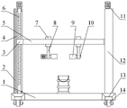
Fig. 1 is a schematic view of the structure of the barreled paint pouring device of the present invention.
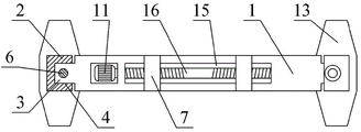
Fig. 2 is a schematic view of a top view of the barreled paint pouring device of the present invention.
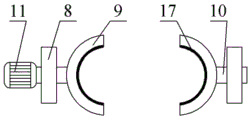
Fig. 3 is a top view of the clamping portion of the barreled paint pouring device of the present invention.
In the figure: 1. the device comprises a supporting bottom plate 2, a supporting upright post A3, a sliding block A4, a vertical sliding groove 5, a horizontal supporting frame 6, a vertical threaded rod 7, a sliding block B8, a supporting seat 9, a clamping plate 10, a rotating shaft 11, a rotating motor 12, a supporting upright post B13, supporting legs 14, a moving mechanism 15, a horizontal sliding groove 16, a horizontal threaded rod 17 and a friction pad.
Detailed Description
The present invention will be further described with reference to the accompanying drawings.
Example 1
As shown in fig. 1-3, a barreled paint dumping device comprises a supporting base plate 1, a supporting upright a2 and a supporting upright B12 are respectively fixed on the upper surface of the supporting base plate 1 near the left and right ends, a horizontal supporting frame 5 is arranged between the supporting upright a2 and the supporting upright B12, two ends of the horizontal supporting frame 5 are respectively connected with a sliding block A3, sliding blocks A3 at two ends of the horizontal supporting frame 5 are respectively arranged in vertical sliding grooves 4 on the inner side surfaces of the supporting upright a2 and the supporting upright B12 in a sliding manner, the sliding block A3 is connected with a vertical threaded rod 6 through threads, two ends of the vertical threaded rod 6 are respectively connected with the top end surface and the bottom end surface of the supporting upright a2 and the supporting upright B12 in a rotating manner, a horizontal sliding groove 15 is arranged on the horizontal supporting frame 5, two sliding blocks B7 are arranged in the horizontal sliding groove 15 in a sliding manner, two slider B7 connect the both ends at horizontal threaded rod 16 through threaded connection respectively, the screw thread of horizontal threaded rod 16 both ends revolve to opposite, slider B7's lower terminal surface on be connected with supporting seat 8, supporting seat 8 medial surface on be connected with grip block 9 through the pivot.
When the utility model is used, firstly, the two clamping plates synchronously move towards the middle by rotating the horizontal threaded rod so as to clamp the coating bucket, then the vertical threaded rod is rotated so that the horizontal support frame drives the coating bucket to move upwards to a required height, and finally, the barrel body of the coating bucket rotates a certain angle around the axis direction of the rotating shaft by rotating the rotating shaft on the clamping plates, so that the material in the coating bucket is poured out; the horizontal support frame in the utility model is driven to move up and down by the threaded connection between the vertical threaded rod and the sliding block A, and the moving stability of the lifting platform is good; the distance between the two clamping plates can be adjusted by rotating the horizontal threaded rod, so that the barrel body is clamped or loosened, and the clamping effect is good; the clamping plate A, the clamping plate B and the paint bucket clamped by the clamping plate A can rotate for a certain angle around the axis direction of the rotating shaft by rotating the rotating shaft on the clamping plate, so that the paint in the bucket body is poured out, and the operation is convenient; the clamping mechanism of the coating barrel in the utility model is positioned at the central position of the upper surface of the supporting bottom plate to ensure the stability of the whole device in the working process; generally, the utility model has the advantages of structural design is reasonable, convenient operation, labour saving and time saving.
Example 2
As shown in fig. 1-3, a barreled paint dumping device comprises a supporting base plate 1, a supporting upright a2 and a supporting upright B12 are respectively fixed on the upper surface of the supporting base plate 1 near the left and right ends, a horizontal supporting frame 5 is arranged between the supporting upright a2 and the supporting upright B12, two ends of the horizontal supporting frame 5 are respectively connected with a sliding block A3, sliding blocks A3 at two ends of the horizontal supporting frame 5 are respectively arranged in vertical sliding grooves 4 on the inner side surfaces of the supporting upright a2 and the supporting upright B12 in a sliding manner, the sliding block A3 is connected with a vertical threaded rod 6 through threads, two ends of the vertical threaded rod 6 are respectively connected with the top end surface and the bottom end surface of the supporting upright a2 and the supporting upright B12 in a rotating manner, a horizontal sliding groove 15 is arranged on the horizontal supporting frame 5, two sliding blocks B7 are arranged in the horizontal sliding groove 15 in a sliding manner, the two sliding blocks B7 are respectively connected with two ends of a horizontal threaded rod 16 through threaded connection, the thread turning directions of the two ends of the horizontal threaded rod 16 are opposite, a supporting seat 8 is connected on the lower end face of the sliding block B7, and a clamping plate 9 is connected on the inner side face of the supporting seat 8 through a rotating shaft; the vertical threaded rod 6, the horizontal threaded rod 16 and the rotating shaft 10 are respectively connected with a rotating motor 11; the lower surface of the supporting bottom plate 1 is provided with supporting legs 13 near the left end and the right end respectively; a moving mechanism 14 is arranged on the lower surface of the supporting leg 13, and a brake block is arranged on the moving mechanism 14; the inner side surfaces of the holding plates 9 are respectively provided with friction pads 17.
When the utility model is used, firstly, the two clamping plates synchronously move towards the middle by rotating the horizontal threaded rod so as to clamp the coating bucket, then the vertical threaded rod is rotated so that the horizontal support frame drives the coating bucket to move upwards to a required height, and finally, the barrel body of the coating bucket rotates a certain angle around the axis direction of the rotating shaft by rotating the rotating shaft on the clamping plates, so that the material in the coating bucket is poured out; the horizontal support frame in the utility model is driven to move up and down by the threaded connection between the vertical threaded rod and the sliding block A, and the moving stability of the lifting platform is good; the distance between the two clamping plates can be adjusted by rotating the horizontal threaded rod, so that the barrel body is clamped or loosened, and the clamping effect is good; the clamping plate A, the clamping plate B and the paint bucket clamped by the clamping plate A can rotate for a certain angle around the axis direction of the rotating shaft by rotating the rotating shaft on the clamping plate, so that the paint in the bucket body is poured out, and the operation is convenient; the clamping mechanism of the coating barrel in the utility model is positioned at the central position of the upper surface of the supporting bottom plate to ensure the stability of the whole device in the working process; generally, the utility model has the advantages of structural design is reasonable, convenient operation, labour saving and time saving.
When the utility model is used, firstly, the two clamping plates synchronously move towards the middle by rotating the horizontal threaded rod so as to clamp the coating bucket, then the motor drives the vertical threaded rod to rotate, so that the horizontal support frame drives the coating bucket to move upwards to a required height, and finally the motor drives the rotating shaft on the clamping plates to rotate for a certain angle, so that the coating bucket rotates for a certain angle around the axis direction of the rotating shaft, thereby pouring out the materials in the coating bucket, and the operation is convenient; the horizontal support frame in the utility model is driven to move up and down by the threaded connection between the vertical threaded rod and the sliding block A, and the moving stability of the lifting platform is good; the distance between the two clamping plates can be adjusted by rotating the horizontal threaded rod, so that the barrel body is clamped or loosened, and the clamping effect is good; the clamping mechanism of the coating barrel in the utility model is positioned at the central position of the upper surface of the supporting bottom plate to ensure the stability of the whole device in the working process; a moving mechanism is arranged on the lower surface of the support frame, and a locking block is arranged on the moving mechanism, so that the device can move conveniently; friction pads are respectively arranged on the inner side surfaces of the clamping plates so as to ensure the clamping effect of the clamping plate A and the clamping plate B on the coating barrel; generally, the utility model has the advantages of structural design is reasonable, convenient operation, labour saving and time saving.
Claims (5)
1. The utility model provides a barreled coating pours device, it includes supporting baseplate, its characterized in that: the upper surface of the supporting bottom plate is respectively fixed with a supporting upright A and a supporting upright B at positions close to the left end and the right end, a horizontal supporting frame is arranged between the supporting upright A and the supporting upright B, the two ends of the horizontal supporting frame are respectively connected with a sliding block A, the sliding blocks A at the two ends of the horizontal supporting frame are respectively arranged in vertical sliding grooves on the inner side surfaces of the supporting upright A and the supporting upright B in a sliding way, the sliding block A is connected with a vertical threaded rod through threads, the two ends of the vertical threaded rod are respectively connected with the top end surface and the bottom end surface of the supporting upright A and the supporting upright B in a rotating way, the horizontal supporting frame is provided with a horizontal sliding groove, the horizontal sliding groove is internally provided with two sliding blocks B, the two sliding blocks B are respectively connected with the two ends of the horizontal threaded rod through threads, and the thread directions at the two, the lower end face of the sliding block B is connected with a supporting seat, and the inner side face of the supporting seat is connected with a clamping plate through a rotating shaft.
2. The barreled paint pouring device of claim 1, wherein: and the vertical threaded rod, the horizontal threaded rod and the rotating shaft are respectively connected with a rotating motor.
3. The barreled paint pouring device of claim 1, wherein: the lower surface of the supporting bottom plate is provided with supporting legs at positions close to the left end and the right end respectively.
4. The barreled paint pouring device of claim 3, wherein: the lower surface of the supporting leg is provided with a moving mechanism, and the moving mechanism is provided with a brake block.
5. The barreled paint pouring device of claim 1, wherein: the inner side surfaces of the clamping plates are respectively provided with a friction pad.
Priority Applications (1)
| Application Number | Priority Date | Filing Date | Title |
|---|---|---|---|
| CN202020364285.8U CN211846401U (en) | 2020-03-20 | 2020-03-20 | Barreled coating dumping device |
Applications Claiming Priority (1)
| Application Number | Priority Date | Filing Date | Title |
|---|---|---|---|
| CN202020364285.8U CN211846401U (en) | 2020-03-20 | 2020-03-20 | Barreled coating dumping device |
Publications (1)
| Publication Number | Publication Date |
|---|---|
| CN211846401U true CN211846401U (en) | 2020-11-03 |
Family
ID=73134888
Family Applications (1)
| Application Number | Title | Priority Date | Filing Date |
|---|---|---|---|
| CN202020364285.8U Expired - Fee Related CN211846401U (en) | 2020-03-20 | 2020-03-20 | Barreled coating dumping device |
Country Status (1)
| Country | Link |
|---|---|
| CN (1) | CN211846401U (en) |
Cited By (1)
| Publication number | Priority date | Publication date | Assignee | Title |
|---|---|---|---|---|
| CN112591659A (en) * | 2020-12-17 | 2021-04-02 | 江苏泰仓农化有限公司 | Quick loading attachment of polyurethane cross-linking agent DI-DMA |
-
2020
- 2020-03-20 CN CN202020364285.8U patent/CN211846401U/en not_active Expired - Fee Related
Cited By (1)
| Publication number | Priority date | Publication date | Assignee | Title |
|---|---|---|---|---|
| CN112591659A (en) * | 2020-12-17 | 2021-04-02 | 江苏泰仓农化有限公司 | Quick loading attachment of polyurethane cross-linking agent DI-DMA |
Similar Documents
| Publication | Publication Date | Title |
|---|---|---|
| CN209618404U (en) | A kind of stable lifting dumping equipment | |
| CN116081453A (en) | Precast concrete lifting appliance | |
| CN109573833A (en) | A kind of interlocking segment top cover die lifting turnover device | |
| CN113200461A (en) | Hydraulic and hydroelectric engineering construction lifting equipment | |
| CN205366205U (en) | Steel strip coils upset, swivel work head | |
| CN108584727B (en) | Water tank hoisting equipment and hoisting method | |
| CN112609998A (en) | Supporting platform for mounting steel structure industrial factory building | |
| CN208980282U (en) | A kind of elevator for lead of power overhauling tower | |
| CN216997313U (en) | Multi-functional hoist device of architectural equipment | |
| CN206502513U (en) | A kind of adjustable hoisting steel plate fixture | |
| CN203781372U (en) | Paint bucket clamping and emptying device | |
| CN207194456U (en) | A kind of high intensity support meanss for building | |
| CN211544866U (en) | Liftable conveyer belt support | |
| CN211198466U (en) | Sand core overturning and hoisting device | |
| CN218231587U (en) | Chemical industry pipeline overhauls uses hoist and mount frame | |
| CN210764010U (en) | Anti-swing device of crane sling | |
| CN215047953U (en) | Butt joint positioning device for hoisting prefabricated box girder | |
| CN215592438U (en) | A high-precision lifting device suitable for mold release | |
| CN221274605U (en) | Automatic lifting unloader convenient to installation | |
| CN210966950U (en) | V method casting sand box device of turning over | |
| CN218950920U (en) | Crane convenient for fixing materials | |
| CN215249040U (en) | Adjustable hoisting mechanism for electrolytic cell | |
| CN218579506U (en) | Hoisting device is laid to city bridge floor | |
| CN113664973B (en) | A kind of auxiliary tool for making concrete test block | |
| CN218595863U (en) | Multifunctional lifting appliance for oblique roof of antique building |
Legal Events
| Date | Code | Title | Description |
|---|---|---|---|
| GR01 | Patent grant | ||
| GR01 | Patent grant | ||
| CF01 | Termination of patent right due to non-payment of annual fee |
Granted publication date: 20201103 |
|
| CF01 | Termination of patent right due to non-payment of annual fee |