CN211827116U - Dustproof computer machine case dispels heat - Google Patents
Dustproof computer machine case dispels heat Download PDFInfo
- Publication number
- CN211827116U CN211827116U CN202020549360.8U CN202020549360U CN211827116U CN 211827116 U CN211827116 U CN 211827116U CN 202020549360 U CN202020549360 U CN 202020549360U CN 211827116 U CN211827116 U CN 211827116U
- Authority
- CN
- China
- Prior art keywords
- case
- rectangular
- fixedly connected
- groove
- straight rod
- Prior art date
- Legal status (The legal status is an assumption and is not a legal conclusion. Google has not performed a legal analysis and makes no representation as to the accuracy of the status listed.)
- Expired - Fee Related
Links
- 230000017525 heat dissipation Effects 0.000 claims abstract description 10
- 239000000428 dust Substances 0.000 claims description 16
- 238000001816 cooling Methods 0.000 description 2
- 230000004075 alteration Effects 0.000 description 1
- 230000009286 beneficial effect Effects 0.000 description 1
- 230000000694 effects Effects 0.000 description 1
- 238000000034 method Methods 0.000 description 1
- 238000012986 modification Methods 0.000 description 1
- 230000004048 modification Effects 0.000 description 1
- 230000002265 prevention Effects 0.000 description 1
- 238000006467 substitution reaction Methods 0.000 description 1
Images


Landscapes
- Cooling Or The Like Of Electrical Apparatus (AREA)
Abstract
The utility model relates to the technical field of computers, and discloses a heat-dissipation dustproof computer case, which comprises a case, wherein a rectangular block is placed at the upper end of the case, rectangular through grooves are formed in the upper surface of the rectangular block, a hinged plate is placed on the right side of the rectangular block, the bottom of the hinged plate is fixedly connected with the upper surface of the case, the left surface of the hinged plate is fixedly connected with the right surface of the rectangular block, rectangular through grooves a are uniformly formed in the left surface of the case, a dustproof net is placed in each rectangular through groove a, when a power switch is pressed, when the power switch is started, a lifter fixed at the bottom of a rectangular plate fixed on the inner wall of the case can be lifted to enable a straight rod to move up and down, then the straight rod a fixed on the straight rod can also move up and down, the sample straight rod a can be separated from the rectangular through grooves, then a motor positioned on the inner wall of the right side of, the turn bar then rotates, and rotation of the turn bar causes the disk to rotate.
Description
Technical Field
The utility model relates to a computer technology field specifically is a dustproof computer machine case of heat dissipation.
Background
In the use process of a computer, the requirement on the temperature is sensitive, and the operation of internal components can be influenced due to high temperature, so that radiating holes can be formed in the wall of a case body of the computer case, particularly a detachable side cover, to radiate heat of a main board in the case, and most cases adopting an air cooling mode can be additionally provided with a fan to enhance the cooling of the main board; but because of reasons such as long-time placing, have a lot of dust to enter into quick-witted incasement portion from the louvre, the dust can produce more serious influence to computer performance, can follow the dust and get into effective dust removal in the source of quick-witted incasement.
SUMMERY OF THE UTILITY MODEL
Technical problem to be solved
Not enough to prior art, the utility model provides a dustproof computer machine case of heat dissipation possesses advantages such as dustproof and heat dissipation, has solved the problem that does not go dirt.
(II) technical scheme
In order to achieve the above object, the utility model provides a following technical scheme: the utility model provides a dustproof computer machine case dispels heat, includes the quick-witted case, the rectangular block has been placed to the upper end of machine case, the rectangle recess has been seted up to the upper surface of rectangular block, the articulated slab has been placed on the right side of rectangular block, the bottom and the quick-witted case upper surface fixed connection of articulated slab, the left side of articulated slab and the right fixed connection of rectangular block, the logical groove an of rectangle has evenly been seted up such as the left side of machine case, every the dust screen has been placed to the inside that the groove a was led to the rectangle.
Preferably, motors are uniformly fixed on the inner wall of the right side of the case, a rotating rod is fixedly connected to the left side of each motor, a disc is fixedly connected to the left side of each rotating rod, and fan blades are uniformly and fixedly connected to the side surface of each disc.
Preferably, the upper end of the inner wall of the left side of the case is fixedly connected with a rectangular plate, the bottom of the rectangular plate is fixedly connected with an electric lifter, the lower end of the electric lifter is fixedly connected with a straight rod, the left side of the straight rod is fixedly and uniformly and fixedly connected with straight rods a, and each straight rod a is located on the rectangular through groove a.
Preferably, the size of the straight rod a is the same as that of the rectangular through groove a, a circular through groove is formed in the upper end of the front face of the case, and a power switch is placed inside the circular through groove.
(III) advantageous effects
Compared with the prior art, the utility model provides a dustproof computer machine case of heat dissipation possesses following beneficial effect:
1. the heat-dissipation dustproof computer case can enable a straight rod to move up and down by pressing down a power switch when the power switch is started, and enable a lifter fixed at the bottom of a rectangular plate fixed on the upper surface of the inner wall of the case to lift up and down, and enable a straight rod a fixed on the upper surface of the straight rod to move up and down at the same time, the straight rod a can be separated from a rectangular through groove, the sample can block an air outlet when the case is not used, dust can be prevented from entering the case, then a motor positioned on the inner wall of the right side of the case is started at the time, then a rotating rod rotates, the rotation of the rotating rod can enable a disc to rotate, and a fan blade fixed on the side surface of the disc can rotate by the sample, so that wind is generated, parts inside a computer can be dissipated, and meanwhile, the wind goes out through the rectangular through groove, and meanwhile, a dustproof net fixed inside the rectangular through groove is, can prevent that the dust from getting into, this device can provide two-layer protection through above step when quick-witted case is not, prevents that the dust from getting into quick-witted case in the middle of, also can dispel the heat when can clearing up the dust screen during the start.
2. This dustproof computer machine case of heat dissipation is not convenient for carry through current most quick-witted case, and the rectangle that the upper end of machine case was placed this time leads to the groove through the rectangle that the upper surface of rectangle piece was seted up simultaneously, then the lower surface right side of rectangle piece passes through the articulated slab with the upper surface of machine case to be connected, thereby can form the handle, when needs carry out the machine case and carry, conveniently save trouble, can not account for the place.
Drawings
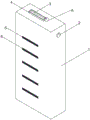
Fig. 1 is a schematic view of the structure of the heat-dissipating dustproof computer case of the present invention;
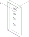
fig. 2 is a schematic view of the internal structure of the heat-dissipating dustproof computer case of the present invention;
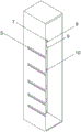
FIG. 3 is a schematic view of the heat dissipation and dust prevention computer case of the present invention;
FIG. 4 is an enlarged schematic view of the structure at A of FIG. 1 according to the present invention;
fig. 5 is an enlarged schematic view of fig. 2 according to the present invention.
In the figure: the device comprises a case 1, a power switch 2, a rectangular through groove 3, a rectangular block 4, a rectangular through groove 5, a dustproof net 6, a rectangular plate 7, an electric lifter 8, a straight rod 9, a straight rod 10, a hinged plate 11, fan blades 12, a disc 13, a rotating rod 14 and a motor 15.
Detailed Description
The technical solutions in the embodiments of the present invention will be described clearly and completely with reference to the accompanying drawings in the embodiments of the present invention, and it is obvious that the described embodiments are only some embodiments of the present invention, not all embodiments. Based on the embodiments in the present invention, all other embodiments obtained by a person skilled in the art without creative work belong to the protection scope of the present invention.
Referring to fig. 1-5, a heat-dissipating and dust-proof computer case comprises a case 1, a rectangular block 4 is placed at the upper end of the case 1, a rectangular groove 3 is formed on the upper surface of the rectangular block 4, a hinged plate 11 is placed on the right side of the rectangular block 4, the bottom of the hinged plate 11 is fixedly connected with the upper surface of the case 1, the left surface of the hinged plate 11 is fixedly connected with the right surface of the rectangular block 4, rectangular through grooves a5 are uniformly formed on the left surface of the case 1, a dust-proof net 6 is placed in each rectangular through groove a5, motors 15 are uniformly fixed on the inner wall of the right surface of the case 1, a rotating rod 14 is fixedly connected to the left surface of each motor 15, a disc 13 is fixedly connected to the left surface of each rotating rod 14, fan blades 12 are uniformly fixedly connected to the side surface of each disc 13, a rectangular plate 7 is fixedly connected to the upper end of the inner wall of, lower extreme fixedly connected with straight-bar 9 of electric lift 8, the left surface of straight-bar 9 is fixed etc. even fixedly connected with straight-bar a10, and every straight-bar a10 all is located the logical groove a5 of rectangle, and the size of straight-bar a10 is the same with the size that the logical groove a5 of rectangle, and circular logical groove has been seted up to the positive upper end of quick-witted case 1, and switch 2 has been placed to the inside that circular led to the groove.
When in use, the utility model is used,
first, when the power switch 2 is pressed, and the power switch 2 is started, the lifter 8 fixed at the bottom of the rectangular plate 7 fixed on the upper wall of the case can be lifted to move the straight rod 9 up and down, then the straight rod a10 fixed on the upper surface of the straight rod 9 can also move up and down, the straight rod a10 can be separated from the rectangular through groove 5, the air outlet can be blocked when the case is not used, dust can be prevented from entering the case, then the motor 15 positioned on the inner wall of the right side of the case is started, the rotating rod 14 rotates to rotate the disc 13, the fan blades 12 fixed on the side surface of the disc 13 can be rotated by the aid of the rotating rod 14, wind is generated, heat dissipation can be performed on parts inside the model 1, and meanwhile, the wind exits through the rectangular through groove 5, simultaneously, the dust screen 6 fixed inside the rectangular through groove 5 can prevent dust from entering, and the device can provide two layers of protection when the case is not used through the steps, so that the dust is prevented from entering the case, and the dust screen can be cleaned and cooled when the device is started.
The second step, the transport of current most quick-witted case is not convenient for, rectangular block 4 that the upper end of machine case 1 was placed this time, the rectangle that the upper surface of rectangular block 4 was seted up leads to groove 3 simultaneously, then the lower surface right side of rectangular block 4 is connected through articulated slab 11 with the upper surface of machine case 1 to can form the handle, when needs carry the machine case, conveniently save trouble, can not take up an area of.
Although embodiments of the present invention have been shown and described, it will be appreciated by those skilled in the art that changes, modifications, substitutions and alterations can be made in these embodiments without departing from the principles and spirit of the invention, the scope of which is defined in the appended claims and their equivalents.
Claims (5)
1. The utility model provides a dustproof computer machine case of heat dissipation, includes quick-witted case (1), its characterized in that: rectangular block (4) have been placed to the upper end of quick-witted case (1), logical groove (3) have been seted up to the rectangle to the upper surface of rectangular block (4), articulated slab (11) have been placed on the right side of rectangular block (4), fixed surface is connected on the bottom of articulated slab (11) and quick-witted case (1), the left surface of articulated slab (11) and the right fixed connection of rectangular block (4), logical groove a (5) of rectangle have evenly been seted up such as the left surface of machine case (1), every dust screen (6) have been placed to the inside that the groove a (5) was led to the rectangle.
2. The heat-dissipating and dust-proof computer case according to claim 1, wherein: the fan case is characterized in that motors (15) are uniformly fixed on the inner wall of the right side of the case (1) and the like, each motor (15) is fixedly connected with a rotating rod (14) on the left side, each rotating rod (14) is fixedly connected with a disc (13) on the left side, and each disc (13) is fixedly connected with fan blades (12) on the side surface and the like.
3. The heat-dissipating and dust-proof computer case according to claim 1, wherein: the improved cabinet is characterized in that a rectangular plate (7) is fixedly connected to the upper end of the inner wall of the left side of the cabinet (1), an electric lifter (8) is fixedly connected to the bottom of the rectangular plate (7), a straight rod (9) is fixedly connected to the lower end of the electric lifter (8), the left side of the straight rod (9) is fixedly and uniformly fixedly connected with straight rods a (10), and each straight rod a (10) is located on the rectangular through groove a (5).
4. The heat-dissipating and dust-proof computer case according to claim 3, wherein: the size of the straight rod a (10) is the same as that of the rectangular through groove a (5).
5. The heat-dissipating and dust-proof computer case according to claim 1, wherein: a round through groove is formed in the upper end of the front face of the case (1), and a power switch (2) is placed inside the round through groove.
Priority Applications (1)
| Application Number | Priority Date | Filing Date | Title |
|---|---|---|---|
| CN202020549360.8U CN211827116U (en) | 2020-04-14 | 2020-04-14 | Dustproof computer machine case dispels heat |
Applications Claiming Priority (1)
| Application Number | Priority Date | Filing Date | Title |
|---|---|---|---|
| CN202020549360.8U CN211827116U (en) | 2020-04-14 | 2020-04-14 | Dustproof computer machine case dispels heat |
Publications (1)
| Publication Number | Publication Date |
|---|---|
| CN211827116U true CN211827116U (en) | 2020-10-30 |
Family
ID=73142871
Family Applications (1)
| Application Number | Title | Priority Date | Filing Date |
|---|---|---|---|
| CN202020549360.8U Expired - Fee Related CN211827116U (en) | 2020-04-14 | 2020-04-14 | Dustproof computer machine case dispels heat |
Country Status (1)
| Country | Link |
|---|---|
| CN (1) | CN211827116U (en) |
-
2020
- 2020-04-14 CN CN202020549360.8U patent/CN211827116U/en not_active Expired - Fee Related
Similar Documents
| Publication | Publication Date | Title |
|---|---|---|
| CN207976827U (en) | The computer cabinet of good heat dissipation effect | |
| CN215833832U (en) | Server monitoring all-in-one machine capable of guaranteeing cooling effect | |
| CN218100150U (en) | Computer radiator convenient to installation butt joint | |
| CN210488475U (en) | Heat radiation structure for industrial control host computer convenient to dismouting | |
| CN214409894U (en) | Automatic change computer constant temperature equipment | |
| CN215416567U (en) | An easy-to-clean computer case | |
| CN212322182U (en) | Dustproof cooling device of electronic computer | |
| CN210052112U (en) | Computer machine case heat abstractor | |
| CN209843544U (en) | Single-phase fling-cut switch of intelligence | |
| CN209526403U (en) | A kind of electric power cabinet dust cooling device | |
| CN207560542U (en) | A kind of special machine cabinet of computer application system | |
| CN221930331U (en) | Equipment cabinet dummy load structure | |
| CN220492520U (en) | Ventilation power distribution cabinet | |
| CN215068059U (en) | Radiating computer machine case | |
| CN220711272U (en) | Motor energy-saving device | |
| CN221926580U (en) | Monitoring device for high-frequency switching power supply | |
| CN216352185U (en) | A portable computer heat dissipation and dustproof device for enterprise workshop | |
| CN217563332U (en) | Power dispatching management device | |
| CN211087054U (en) | Novel computer display screen for information technology development | |
| CN224082006U (en) | Disassembly-free chassis fan | |
| CN213739832U (en) | A kind of cellulose fiber yarn-dyed fabric yarn processing transmission control device | |
| CN219370299U (en) | Radiating box capable of removing dust | |
| CN218158906U (en) | Extensible multi-field fusion database server | |
| CN217484804U (en) | Dustproof device for computer | |
| CN221079266U (en) | A computer radiator |
Legal Events
| Date | Code | Title | Description |
|---|---|---|---|
| GR01 | Patent grant | ||
| GR01 | Patent grant | ||
| CF01 | Termination of patent right due to non-payment of annual fee | ||
| CF01 | Termination of patent right due to non-payment of annual fee |
Granted publication date: 20201030 Termination date: 20210414 |