CN211820655U - Speed reducer with skewed tooth clutch - Google Patents
Speed reducer with skewed tooth clutch Download PDFInfo
- Publication number
- CN211820655U CN211820655U CN201922002132.9U CN201922002132U CN211820655U CN 211820655 U CN211820655 U CN 211820655U CN 201922002132 U CN201922002132 U CN 201922002132U CN 211820655 U CN211820655 U CN 211820655U
- Authority
- CN
- China
- Prior art keywords
- skewed tooth
- speed reducer
- flange
- shaft
- shifting
- Prior art date
- Legal status (The legal status is an assumption and is not a legal conclusion. Google has not performed a legal analysis and makes no representation as to the accuracy of the status listed.)
- Active
Links
- 239000003638 chemical reducing agent Substances 0.000 title claims abstract description 30
- 230000000694 effects Effects 0.000 claims abstract description 18
- 230000002093 peripheral effect Effects 0.000 claims abstract description 7
- 230000009467 reduction Effects 0.000 claims description 11
- 238000004519 manufacturing process Methods 0.000 abstract description 3
- 239000004568 cement Substances 0.000 abstract description 2
- 238000012423 maintenance Methods 0.000 abstract 1
- 230000002035 prolonged effect Effects 0.000 abstract 1
- 230000008901 benefit Effects 0.000 description 3
- 230000004048 modification Effects 0.000 description 3
- 238000012986 modification Methods 0.000 description 3
- 239000010687 lubricating oil Substances 0.000 description 2
- 230000005540 biological transmission Effects 0.000 description 1
- 230000008859 change Effects 0.000 description 1
- 238000005516 engineering process Methods 0.000 description 1
- 238000000034 method Methods 0.000 description 1
- 230000008569 process Effects 0.000 description 1
- 238000000926 separation method Methods 0.000 description 1
Images

Landscapes
- Mechanical Operated Clutches (AREA)
Abstract
The embodiment of the utility model discloses decelerator with skewed tooth clutch relates to cement manufacture equipment field, including the speed reducer host computer, slow turning speed reducer, the flange, shift fork device and skewed tooth clutch shift, skewed tooth clutch includes activity skewed tooth dish and fixed skewed tooth dish, and fixed skewed tooth dish cover is located on the power input shaft of speed reducer host computer, and on the power output shaft of slow turning speed reducer was located to activity skewed tooth dish cover, be provided with on power output shaft's the outer peripheral face along axially extended spline, the internal surface of activity skewed tooth dish be provided with spline sliding fit's spline groove. The inclined tooth clutch with better load performance is used for replacing the overrunning clutch, so that the double-drive mode of the hoister is better matched, the service life of the speed reducer is effectively prolonged, the maintenance difficulty is reduced, and the use cost is reduced. The guide sleeve is arranged at the edge of one side, close to the fixed oblique fluted disc, of the movable oblique fluted disc, and plays a role in guiding the movable oblique fluted disc, so that the moving precision of the movable oblique fluted disc is improved.
Description
Technical Field
The embodiment of the utility model provides a relate to cement manufacture equipment field, concretely relates to decelerator with skewed tooth clutch.
Background
The speed reducer is used for a bucket elevator, and the bucket elevator is generally provided with two speed reducers because of a large load. In the using process, the failure rate of the overrunning clutch of the original belt is found to be too high, and 1.5 spare parts are replaced each year basically. Great loss is caused to the overhaul and the production, and great direct economic loss is caused to the replacement of the overrunning clutch.
Clutch failure has been analyzed for several reasons:
1. the bucket elevator has large load, the design capacity is 1000t/h, and the bucket elevator is about 650t/h in actual use. Therefore, the design of the chain plate of the elevator is large, and the weight of the whole hanging chain is estimated to be 15 t. The weight of each bucket was 150 kg/bucket, and the weight of 161 buckets was 24t in total. The bucket elevator thus has a weight of approximately 40t when empty, which places a significant load on the overrunning clutch.
2. The bucket elevator is in a double-drive mode, and when the bucket elevator is pneumatically rotated slowly, the synchronism of the two slow-rotation speed reducers cannot be guaranteed, so that one overrunning clutch bears twice the load instantly.
3. The damage probability of the overrunning clutch in winter is higher than that of the overrunning clutch in summer, and the main reason is that the temperature is low in winter and can reach-15 ℃. At such temperatures, the lubricating oil becomes particularly poor in fluidity and does not provide good protection to the overrunning clutch, resulting in damage to the clutch.
SUMMERY OF THE UTILITY MODEL
Therefore, the embodiment of the utility model provides a decelerator with skewed tooth clutch to there is the part to damage easily in solving current decelerator, and use cost is high, maintains the big problem of the degree of difficulty.
In order to achieve the above object, an embodiment of the present invention provides a reduction gear with an oblique tooth clutch, where the reduction gear with an oblique tooth clutch includes a main reducer, a slow turning speed reducer and a flange, one end of the flange is connected to a housing of the main reducer, and the other end of the flange is connected to a housing of the slow turning speed reducer; still including the shift fork device of shifting with set up in skewed tooth clutch in the flange, skewed tooth clutch includes activity skewed tooth dish and fixed skewed tooth dish, fixed skewed tooth dish cover is located on the power input shaft of speed reducer host computer, activity skewed tooth dish cover is located on the power output shaft of slow turning speed reducer, be provided with along axially extended spline on power output shaft's the outer peripheral face, the internal surface of activity skewed tooth dish is provided with the spline groove with spline sliding fit, the shift fork device of shifting is used for driving the axial motion of activity skewed tooth dish along power output shaft to make activity skewed tooth dish and fixed skewed tooth dish realize meshing and separation.
Further, shift fork device of shifting includes initiative declutch shift lever, declutch shift shaft, axle sleeve, driven declutch shift lever and spring, the declutch shift shaft rotationally sets up in the flange, the upper end of declutch shift shaft extends to the outside of flange, the periphery of declutch shift shaft is located to the fixed cover of axle sleeve, the both ends of axle sleeve are provided with the connecting rod respectively, every the one end that the axle sleeve was kept away from to the connecting rod sets up the locating pin, the locating pin inserts and sets up in the ring channel of activity inclined fluted disc outer peripheral face to with ring channel sliding fit, the one end of initiative declutch shift lever is connected with the upper end of declutch shift shaft, the tip of initiative declutch shift lever one end is rotated with the one end of driven declutch shift lever and is connected, the middle part of driven declutch shift lever is passed through the bolt and is.
Further, the flange is a square flange.
Furthermore, the edge of the movable inclined fluted disc close to one side of the fixed inclined fluted disc is provided with a guide sleeve extending along the axial direction, and the periphery of the fixed inclined fluted disc is sleeved with the guide sleeve.
Furthermore, two the connecting rod all with the axle sleeve is perpendicular, and all with axle sleeve welded connection.
The embodiment of the utility model provides a have following advantage:
1. the utility model discloses decelerator with skewed tooth clutch replaces freewheel clutch through the skewed tooth clutch that uses the load performance better to the two forms of driving that cooperate the lifting machine better, effectively prolongs decelerator's life, reduces and maintains the degree of difficulty, reduces use cost.
2. The utility model discloses decelerator with skewed tooth clutch sets up guide sleeve through the border that is close to fixed skewed tooth dish one side at activity skewed tooth dish, and guide sleeve plays the guide effect to activity skewed tooth dish, improves the precision when activity skewed tooth dish removes.
3. The utility model discloses decelerator with skewed tooth clutch through using square flange, can conveniently install shift fork device.
Drawings
In order to more clearly illustrate the embodiments of the present invention or the technical solutions in the prior art, the drawings used in the description of the embodiments or the prior art will be briefly described below. It should be apparent that the drawings in the following description are merely exemplary, and that other embodiments can be derived from the drawings provided by those of ordinary skill in the art without inventive effort.
The structure, ratio, size and the like shown in the present specification are only used for matching with the content disclosed in the specification, so as to be known and read by people familiar with the technology, and are not used for limiting the limit conditions which can be implemented by the present invention, so that the present invention has no technical essential significance, and any structure modification, ratio relationship change or size adjustment should still fall within the scope which can be covered by the technical content disclosed by the present invention without affecting the efficacy and the achievable purpose of the present invention.
Fig. 1 is a schematic cross-sectional view of a reduction gear with a helical gear clutch according to an embodiment of the present invention;
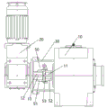
fig. 2 is a schematic top view of a reduction gear with a helical gear clutch according to an embodiment of the present invention;
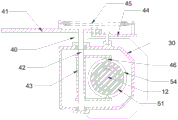
fig. 3 is a schematic cross-sectional view of a reduction gear with a helical gear clutch according to an embodiment of the present invention at a flange.
Description of reference numerals: 10. a main machine of the speed reducer; 11. a power input shaft; 12. a power take-off shaft; 13. a spline; 20. a slow-turning speed reducer; 30. a flange; 40. a shift fork device; 41. an active shift fork lever; 42. a fork shaft; 43. a shaft sleeve; 44. a driven fork lever; 45. a spring; 46. positioning pins; 50. a helical gear clutch; 51. a movable inclined fluted disc; 52. fixing an inclined fluted disc; 53. a guide sleeve; 54. an annular groove.
Detailed Description
The present invention is described in terms of specific embodiments, and other advantages and benefits of the present invention will become apparent to those skilled in the art from the following disclosure. Based on the embodiments in the present invention, all other embodiments obtained by a person skilled in the art without creative work belong to the protection scope of the present invention.
As shown in fig. 2, the reduction gear with the helical tooth clutch includes a main reducer 10, a slow-turning speed reducer 20, a flange 30, a shifting fork device 40 and a helical tooth clutch 50, one end of the flange 30 is connected with a housing of the main reducer 10 through a bolt, the other end of the flange 30 is connected with a housing of the slow-turning speed reducer 20 through a bolt, the flange 30 is a square flange in the embodiment, and the shifting fork device 40 can be conveniently installed by using the square flange.
As shown in fig. 1, the helical clutch 50 is used for connecting the power input shaft 11 and the power output shaft 12, so as to achieve power transmission, the helical clutch 50 is disposed inside the flange 30, the helical clutch 50 includes a movable helical gear 51 and a fixed helical gear 52, the fixed helical gear 52 is sleeved on the power input shaft 11 of the main reducer 10, and the power input shaft 11 rotates along with the fixed helical gear 52. The movable inclined fluted disc 51 is sleeved on the power output shaft 12 of the slow-turning speed reducer 20, splines 13 extending along the axial direction are arranged on the outer peripheral surface of the power output shaft 12, the number of the splines 13 is multiple, spline grooves in sliding fit with the splines 13 are arranged on the inner surface of the movable inclined fluted disc 51, the number and the positions of the spline grooves correspond to those of the splines 13 one by one, through the fit of the splines 13 and the spline grooves, the movable inclined fluted disc 51 can slide along the axial direction of the power output shaft 12, but the movable inclined fluted disc 51 and the spline grooves cannot rotate relatively, and therefore when the power output shaft 12 rotates, the movable inclined fluted disc 51 rotates along with the power output shaft 12. Furthermore, the edge of the movable inclined toothed disc 51 close to one side of the fixed inclined toothed disc 52 is provided with a guide sleeve 53 extending along the axial direction, the guide sleeve 53 is sleeved on the periphery of the fixed inclined toothed disc 52, and the guide sleeve 53 plays a role in guiding the movable inclined toothed disc 51, so that the moving precision of the movable inclined toothed disc 51 can be improved, and the movable inclined toothed disc 51 and the fixed inclined toothed disc 52 can be better meshed. Through using the better skewed tooth clutch 50 of load performance to replace freewheel clutch, skewed tooth clutch 50 has higher structural strength than freewheel clutch, more is suitable for heavy load to the double-drive form of lifting machine is better cooperated, and effective life of decelerator that prolongs, life can reach ten years, reduces use cost, and skewed tooth clutch 50 does not need lubricating oil to lubricate in addition, reduces and maintains the degree of difficulty.
As shown in fig. 3, the shift fork device 40 is used to drive the movable bevel gear plate 51 to move along the axial direction of the power output shaft 12, so that the movable bevel gear plate 51 is engaged with and disengaged from the fixed bevel gear plate 52. The gear-shifting fork device 40 comprises a driving fork rod 41, a fork shaft 42, a shaft sleeve 43, a driven fork rod 44 and a spring 45, wherein a bearing is arranged inside the flange 30, the fork shaft 42 is rotatably arranged in the flange 30 through the bearing, the upper end of the fork shaft 42 extends to the outside of the flange 30, the shaft sleeve 43 is fixedly sleeved on the periphery of the fork shaft 42, two ends of the shaft sleeve 43 are respectively provided with a connecting rod, the two connecting rods are perpendicular to the shaft sleeve 43 and are welded with the shaft sleeve 43, one end of each connecting rod, which is far away from the shaft sleeve 43, is provided with a positioning pin 46, the positioning pin 46 is inserted into an annular groove 54 arranged on the outer peripheral surface of a movable inclined fluted disc 51 and is in sliding fit with the annular groove 54, one end of the driving fork rod 41 is connected with the upper end of the fork shaft 42, the end of the driving fork rod 41 is rotatably connected with one end of the driven fork rod 44, the, the other end of the driven fork lever 44 is connected to the middle of the driving fork lever 41 through a spring 45.
In an initial state, the driving shifting fork rod 41 and the driven shifting fork rod 44 are on the same straight line, at the moment, the spring 45 is in a rope pulling state, the movable inclined fluted disc 51 is meshed with the fixed inclined fluted disc 52, and the power output shaft 12 drives the power input shaft 11 to rotate through the inclined-tooth clutch 50; when the movable inclined toothed disc 51 is required to be separated from the fixed inclined toothed disc 52, pulling the other end of the driving fork rod 41 to rotate in the forward direction, driving the movable inclined toothed disc 51 to slide in the direction away from the fixed inclined toothed disc 52 along the axial direction of the power output shaft 12 by the driving fork rod 41 sequentially through the fork shaft 42 and the connecting rod, and separating the movable inclined toothed disc 51 from the fixed inclined toothed disc 52; when the other end of the driving shifting fork rod 41 is pulled to rotate reversely, the driving shifting fork rod 41 sequentially passes through the shifting fork shaft 42 and the connecting rod to drive the movable inclined fluted disc 51 to slide towards the direction close to the fixed inclined fluted disc 52 along the axial direction of the power output shaft 12, the movable inclined fluted disc 51 is meshed with the fixed inclined fluted disc 52, and due to the elastic force of the spring 45, the driving shifting fork rod 41 and the driven shifting fork rod 44 are always in the same straight line under the condition of no external force, so that the movable inclined fluted disc 51 is meshed with the fixed inclined fluted disc 52.
Although the invention has been described in detail with respect to the general description and the specific embodiments, it will be apparent to those skilled in the art that modifications and improvements can be made based on the invention. Therefore, such modifications and improvements are intended to be within the scope of the invention as claimed.
Claims (5)
1. A speed reduction device with a helical tooth clutch comprises a speed reducer main body, a slow-turning speed reducer and a flange, wherein one end of the flange is connected with a shell of the speed reducer main body, and the other end of the flange is connected with the shell of the slow-turning speed reducer; its characterized in that still including the shift fork device of shifting with set up in skewed tooth clutch in the flange, skewed tooth clutch includes activity skewed tooth dish and fixed skewed tooth dish, fixed skewed tooth dish cover is located on the power input shaft of speed reducer host computer, activity skewed tooth dish cover is located on the power output shaft of slow-turning speed reducer, be provided with along axially extended spline on power output shaft's the outer peripheral face, the internal surface of activity skewed tooth dish is provided with the spline groove with spline sliding fit, the shift fork device of shifting is used for driving the axial motion of activity skewed tooth dish along power output shaft to make the meshing of activity skewed tooth dish and fixed skewed tooth dish realize and separate.
2. A reduction gear unit with helical clutch according to claim 1, the gear-shifting fork-shifting device comprises a driving fork-shifting rod, a fork-shifting shaft, a shaft sleeve, a driven fork-shifting rod and a spring, the shifting fork shaft is rotatably arranged in the flange, the upper end of the shifting fork shaft extends to the outside of the flange, the shaft sleeve is fixedly sleeved on the periphery of the shifting fork shaft, the two ends of the shaft sleeve are respectively provided with a connecting rod, one end of each connecting rod, which is far away from the shaft sleeve, is provided with a positioning pin, the positioning pin is inserted into an annular groove arranged on the outer peripheral surface of the movable inclined fluted disc, and is in sliding fit with the annular groove, one end of the driving shifting fork rod is connected with the upper end of the shifting fork shaft, the end part of one end of the driving shifting fork rod is rotatably connected with one end of the driven shifting fork rod, the middle part of the driven shifting fork rod is rotatably connected with the flange through a bolt, and the other end of the driven shifting fork rod is connected with the middle part of the driving shifting fork rod through a spring.
3. A reduction gear unit with a helical clutch according to claim 1 or 2, characterised in that the flange is a square flange.
4. The reduction gear with a helical clutch according to claim 1 or 2, wherein the edge of the movable helical toothed disc on the side close to the fixed helical toothed disc is provided with a guide sleeve extending in the axial direction, and the guide sleeve is sleeved on the outer periphery of the fixed helical toothed disc.
5. A reduction gear unit with helical clutch according to claim 2, wherein both of said connecting rods are perpendicular to said sleeve and are welded to the sleeve.
Priority Applications (1)
| Application Number | Priority Date | Filing Date | Title |
|---|---|---|---|
| CN201922002132.9U CN211820655U (en) | 2019-11-19 | 2019-11-19 | Speed reducer with skewed tooth clutch |
Applications Claiming Priority (1)
| Application Number | Priority Date | Filing Date | Title |
|---|---|---|---|
| CN201922002132.9U CN211820655U (en) | 2019-11-19 | 2019-11-19 | Speed reducer with skewed tooth clutch |
Publications (1)
| Publication Number | Publication Date |
|---|---|
| CN211820655U true CN211820655U (en) | 2020-10-30 |
Family
ID=73026859
Family Applications (1)
| Application Number | Title | Priority Date | Filing Date |
|---|---|---|---|
| CN201922002132.9U Active CN211820655U (en) | 2019-11-19 | 2019-11-19 | Speed reducer with skewed tooth clutch |
Country Status (1)
| Country | Link |
|---|---|
| CN (1) | CN211820655U (en) |
-
2019
- 2019-11-19 CN CN201922002132.9U patent/CN211820655U/en active Active
Similar Documents
| Publication | Publication Date | Title |
|---|---|---|
| CN101850718A (en) | Energy-saving drive clutch of automobile | |
| CN110486433A (en) | A kind of detachable planetary roller screw pair of nut | |
| CN202832532U (en) | Multifunctional rotary drum device of thin coal seam coal cutter | |
| CN209065326U (en) | High-speed and high-efficiency elevator | |
| CN204185165U (en) | Shaft drive fast reserve strand grinding machine | |
| CN103821881B (en) | Power truck gearshift mechanism | |
| CN205933018U (en) | Two grades of double speed capstan winches | |
| CN102777174B (en) | Multifunctional drum device of thin seam coal shearer | |
| CN208535128U (en) | Tooth-like connection axle sleeve and its lubrication system | |
| CN207748776U (en) | A kind of hydraulic capstan | |
| CN103511493A (en) | Clutch device and reducing mechanism comprising clutch device | |
| CN106321745A (en) | Four-speed transmission for pure-electric vehicle | |
| CN202170981U (en) | Speed changing spindle box of quarrying machine | |
| CN201763900U (en) | Mechanical gearbox for forklift | |
| CN201096149Y (en) | A toothed coupling | |
| CN201931313U (en) | Milling machine feeding mechanism | |
| CN201541486U (en) | Integrated control mechanism of self-propelled device clutch and stepless variable transmission for mower | |
| CN206427961U (en) | Winch hoist | |
| CN106812925B (en) | The multiple-speed gear-box of agricultural crawler body | |
| CN202274005U (en) | Novel friction clutch and separating and combination device thereof | |
| CN202468870U (en) | Speed control system | |
| CN204985539U (en) | Small -size harvester gear case structure | |
| CN208919229U (en) | The ship gear-box of three clutch of One In and Two Out | |
| CN201810697U (en) | Energy-saving drive clutch for vehicle | |
| CN113251118A (en) | AMT two-gear automatic gearbox of electric tricycle |
Legal Events
| Date | Code | Title | Description |
|---|---|---|---|
| GR01 | Patent grant | ||
| GR01 | Patent grant | ||
| CP03 | Change of name, title or address | ||
| CP03 | Change of name, title or address |
Address after: 063708 yangliuzhuang Town, luanzhou City, Tangshan City, Hebei Province Patentee after: Jidong Cement luanzhou Co.,Ltd. Address before: 063708 Jinyu Jidong luanzhou Environmental Protection Technology Co., Ltd., yangliuzhuang Town, luanzhou City, Tangshan City, Hebei Province Patentee before: Jinyu Jidong luanzhou Environmental Protection Technology Co.,Ltd. |