CN211812192U - Detection equipment suitable for clamping irregular battery - Google Patents
Detection equipment suitable for clamping irregular battery Download PDFInfo
- Publication number
- CN211812192U CN211812192U CN201921769880.3U CN201921769880U CN211812192U CN 211812192 U CN211812192 U CN 211812192U CN 201921769880 U CN201921769880 U CN 201921769880U CN 211812192 U CN211812192 U CN 211812192U
- Authority
- CN
- China
- Prior art keywords
- fixedly connected
- clamping
- assembly
- power output
- locking
- Prior art date
- Legal status (The legal status is an assumption and is not a legal conclusion. Google has not performed a legal analysis and makes no representation as to the accuracy of the status listed.)
- Active
Links
Images


Abstract
The utility model discloses a check out test set suitable for irregular battery of clamping, include: a machine platform; the rotary table device is rotatably connected to the middle part of the machine table; the feeding mechanism, the locking and unlocking mechanism, the CCD camera assembly, the laser detection assembly and the discharging mechanism are sequentially arranged beside the turntable device; wherein, carousel device includes: a first stationary base; the driving motor is arranged at the top end part of the first fixed base; the circular turntable is fixedly connected with the power output end of the driving motor; the periphery in circular carousel top portion is rigid coupling has at least two sets of anchor clamps, but anchor clamps clamping irregular battery. The utility model discloses but have the full-automatic tight battery that presss from both sides or loosen, improved the detection efficiency of battery, saved the cost of labor, this equipment structure is simple simultaneously, and easily operation has reduced equipment cost and area, has improved the profit of enterprise, has wide market using value's beneficial effect.
Description
Technical Field
The utility model relates to an automatic technical field. More specifically speaking, the utility model relates to a check out test set suitable for irregular battery of clamping.
Background
On the nonstandard automated production line, when the product is ready to be assembled or after the assembly is completed, the parts before the assembly or the product after the assembly is completed need to be detected, and the existing irregular battery detection equipment has the following problems: the irregular battery is inconvenient to clamp, manual operation is needed in the clamping process, the automation efficiency is low, most of the irregular battery clamping devices adopt a flow line form, the occupied area is large, and therefore the detection device suitable for clamping the irregular battery is needed to be developed to solve the problems.
SUMMERY OF THE UTILITY MODEL
The utility model aims at providing a check out test set suitable for irregular battery of clamping, it adopts anchor clamps and locking and release mechanism to carry out the clamping to irregular battery, can press from both sides tightly or loosen the battery full-automatically, has improved the detection efficiency of battery, has saved the cost of labor, and this equipment structure is simple simultaneously, and easily operation has reduced equipment cost and area, has improved the profit of enterprise, has wide market using value.
In order to achieve these objects and other advantages in accordance with the purpose of the invention, a detecting device for clamping irregular batteries is provided, comprising: a machine platform;
the rotary table device is rotatably connected to the middle part of the machine table; and
the feeding mechanism, the locking and unlocking mechanism, the CCD camera assembly, the laser detection assembly and the discharging mechanism are sequentially arranged beside the turntable device;
wherein, carousel device includes: a first stationary base;
the driving motor is arranged at the top end part of the first fixed base; and
the circular turntable is fixedly connected with the power output end of the driving motor; the periphery in circular carousel top portion is rigid coupling has at least two sets of anchor clamps, but anchor clamps clamping irregular battery.
Preferably, the jig comprises: a fixing plate; and a placing plate arranged at the side of the fixing plate;
the fixing plate is characterized in that a through hole is formed in the fixing plate, a push rod is slidably arranged in the through hole, a placing groove is formed in the placing plate, and fixing pieces are placed in the placing groove.
Preferably, the feeding mechanism includes: a feeding conveying line; and
the first manipulator structure is arranged at the discharge hole of the feeding conveying line;
wherein, material loading transfer chain side is equipped with a inspection calibration subassembly, inspection calibration subassembly includes: a T-shaped fixing plate; and the CCD camera is connected with the T-shaped fixed plate in a sliding manner through a sliding table device.
Preferably, the first robot structure includes: a base;
a controller fixedly connected to the top end part of the base;
the adapter is rotationally connected with the power output end of the controller; and
and the manipulator clamping jaw assembly is fixedly connected with the adapter.
Preferably, feed mechanism side is equipped with a mechanism of blowing, the mechanism of blowing includes: a rotatable fixed bracket; and the blowing head is fixedly connected to the top end of the fixing support and is positioned right above the clamp.
Preferably, the locking and unlocking mechanism includes: fixing the base frame;
the rigid coupling in the drive module at fixed bed frame top portion, drive module includes: a first driving module; the second driving module is connected with the first driving module in a sliding manner;
the first locking and unlocking assembly is connected with the second driving module in a sliding manner; and
and the second locking and unlocking assembly is fixedly connected to the middle part of the fixed pedestal.
Preferably, the first locking and unlocking assembly includes: the first driving cylinder is connected with the second driving module in a sliding manner;
the first clamping jaw is fixedly connected with the power output end of the first driving cylinder; and
the limiting buffer assemblies are fixedly connected to the left end and the right end of the first driving cylinder;
the second locking and unlocking assembly includes: a second driving cylinder;
the thumb cylinder is fixedly connected with the power output end of the second driving cylinder; and
the second clamping jaw is fixedly connected with the power output end of the thumb cylinder;
the thumb cylinder is fixedly connected with the power output end of the second driving cylinder through an adapter plate.
Preferably, the CCD camera assembly includes: a support frame;
the first industrial camera is connected to the top end part of the support frame in a vertically reciprocating sliding mode and is connected with the support frame in a sliding mode through a connecting frame; and
and the plane light source is arranged right below the first industrial camera and fixedly connected to the surface of the machine table through a second fixing base.
Preferably, the laser inspection assembly includes: a first conveying module;
the connecting seat is connected with the first conveying module in a sliding manner;
the second conveying module and the first laser sensor are fixedly connected to the side surface of the top end of the connecting seat, the first laser sensor is fixedly connected with the power output end of the second conveying module, and
and the second laser sensor is fixedly connected to the side surface of the bottom end of the connecting seat.
Preferably, the blanking mechanism includes: a blanking conveying line; and
and the second manipulator structure is arranged at the feed inlet position of the blanking conveying line.
The utility model discloses at least, include following beneficial effect: the utility model provides a check out test set suitable for irregular battery of clamping, it adopts anchor clamps and locking and release mechanism to carry out the clamping to irregular battery, can press from both sides tightly or loosen the battery full-automatically, has improved the detection efficiency of battery, has saved the cost of labor, and this equipment structure is simple simultaneously, and easily operation has reduced equipment cost and area, has improved enterprise's profit, has wide market using value.
Additional advantages, objects, and features of the invention will be set forth in part in the description which follows and in part will become apparent to those having ordinary skill in the art upon examination of the following or may be learned from practice of the invention.
Drawings
Fig. 1 is a schematic structural diagram of an embodiment of the present invention;
fig. 2 is a schematic structural diagram of another view angle according to an embodiment of the present invention;
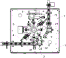
fig. 3 is a top view of an embodiment of the present invention;
fig. 4 is a schematic structural diagram of a turntable device according to an embodiment of the present invention;
fig. 5 is a schematic structural diagram of a clamp according to an embodiment of the present invention;
FIG. 6 is a schematic structural view of a fixing plate according to an embodiment of the present invention;
fig. 7 is a schematic structural view of a placement board according to an embodiment of the present invention;
fig. 8 is a schematic structural view of the inside of the fixing plate according to an embodiment of the present invention;
fig. 9 is a schematic structural view of a push rod according to an embodiment of the present invention;
fig. 10 is a schematic structural diagram of a first robot structure according to an embodiment of the present invention;
fig. 11 is a schematic structural view of a robot gripper assembly according to an embodiment of the present invention;
fig. 12 is a schematic structural diagram of a calibration verification assembly according to an embodiment of the present invention;
fig. 13 is a schematic structural diagram of a CCD camera component according to an embodiment of the present invention;
fig. 14 is a schematic structural diagram of a laser detection assembly according to an embodiment of the present invention;
fig. 15 is a schematic structural diagram of an air blowing mechanism according to an embodiment of the present invention;
fig. 16 is a schematic structural view of a locking and unlocking mechanism according to an embodiment of the present invention;
fig. 17 is a schematic structural view of a first locking and unlocking assembly according to an embodiment of the present invention;
fig. 18 is a schematic structural view of a second locking and unlocking assembly according to an embodiment of the present invention.
Detailed Description
The foregoing and other objects, features, aspects and advantages of the present invention will become more apparent to those skilled in the art from the following detailed description, which, taken in conjunction with the annexed drawings, discloses a more detailed description of the present invention, which will enable those skilled in the art to make and use the present invention. In the drawings, the shape and size may be exaggerated for clarity, and the same reference numerals will be used throughout the drawings to designate the same or similar components. In the following description, terms such as center, thickness, height, length, front, back, rear, left, right, top, bottom, upper, lower, and the like are used based on the orientation or positional relationship shown in the drawings. In particular, "height" corresponds to the dimension from top to bottom, "width" corresponds to the dimension from left to right, and "depth" corresponds to the dimension from front to back. These relative terms are for convenience of description and are not generally intended to require a particular orientation. Terms concerning attachments, coupling and the like (e.g., "connected" and "attached") refer to a relationship wherein structures are secured or attached, either directly or indirectly, to one another through intervening structures, as well as both movable or rigid attachments, unless expressly described otherwise.
As an embodiment of the utility model, refer to fig. 1 ~ 18, the utility model provides a check out test set suitable for irregular battery of clamping, it includes: a machine table 1;
the rotary table device 2 is rotatably connected to the middle part of the machine table 1; and
the feeding mechanism 3, the locking and unlocking mechanism 4, the CCD camera component 5, the laser detection component 6 and the blanking mechanism 7 are sequentially arranged beside the turntable device 2;
wherein the carousel means 2 comprises: a first stationary base 21;
a drive motor 22 provided at the top end of the first fixed base 21; and
a circular turntable 23 fixedly connected with the power output end of the driving motor 22; at least two groups of clamps 24 are fixedly connected to the periphery of the top end part of the circular turntable 23, and the clamps 24 can clamp irregular batteries.
Further, referring to fig. 5 to 9, the jig 24 includes: a fixing plate 241; and a placing plate 242 provided beside the fixing plate 241;
a through hole 2414 is opened inside the fixing plate 241, a push rod 244 is slidably disposed inside the through hole 2414, a placing slot 2421 is opened inside the placing plate 242, and the fixing plate 243 is placed on the placing slot 2421.
In a preferred embodiment, the fixing piece 243 includes: a first clamped portion 2431, wherein the first clamped portion 2431 can be clamped by a locking and unlocking mechanism, so that the fixing plate 243 can move to fix and limit the battery; and a first positioning portion 2432 integrally formed at the bottom end of the first clamped portion 2431, coupled to the first clamped portion 2431, and extending downward from the bottom end of the first clamped portion 2431 in a vertical direction.
The left and right bottom ends of the first clamped portion 2431 are provided with at least one shoulder 2433, and the shoulder 2433 is integrally combined with the first clamped portion 2431 and extends outwards from the left and right ends of the first clamped portion 2431. The shoulder 2433 is in contact with the battery and presses and fixes the battery from the left and right ends, respectively.
The front side and the rear side of the fixing plate 243 are respectively provided with a limiting groove 2434, the limiting groove 2434 can be clamped with a bulge on the surface of the battery, so that the battery is limited and fixed, the bottom end of the first positioning portion 2432 is provided with a positioning hole 2432a, and the positioning hole 2432 can be clamped with the push rod 244, so that the fixing plate 243 is fixed, and the battery is fixed.
In a preferred embodiment, the width of the first positioning portion 2432 is gradually reduced at the left and right sides, and the thickness of the front and rear ends is gradually reduced, so that the first positioning portion 2432 can be inserted into the positioning groove 2412a conveniently.
Furthermore, a through groove 2411 is formed in the middle of the fixing plate 241, a supporting portion 2412 is arranged in the through groove 2411, and the supporting portion 2412 is fixedly connected with the side wall of the through groove 2411 through a connecting portion 2413. A positioning groove 2412a is formed inside the supporting portion 2412, the positioning groove 2412a is matched with the first positioning portion 2432, the positioning groove 2412a is communicated with the through hole 2434, and the positioning groove 2412a can be clamped with the first positioning portion 2432. The top end portion of the supporting portion 2412 is provided with a first clamping groove 2412b for avoiding the workpiece, and the first clamping groove 2412b can clamp the workpiece while avoiding the workpiece. The left and right sides of the fixing plate 241 are fixedly connected with limit blocks 2415. In a preferred embodiment, a second slot 2415a is formed at the top end of the limit block 2415, and the second slot 2415a can clamp the left side and the right side of the battery.
Further, the push rod 244 includes: a second positioning portion 2441 at a front end of the push rod 244; the second positioning portion 2441 is matched with the positioning hole 2432 a; a limit portion 2442 located at the middle of the push rod 244; and a second clamped portion 2443 located at the end of the push rod 244, wherein a clamping groove 2443a is formed on the surface of the second clamped portion 2443. In a preferred embodiment, the front end of the second locator 2441 is tapered to facilitate the second locator. Inserted into the positioning hole 2432 a.
Further, the feed mechanism 3 includes: a feeding conveyor line 31; and
the first manipulator structure 32 is arranged at the discharge hole of the feeding conveying line 31;
wherein, material loading transfer chain 31 side is equipped with a check calibration subassembly 33, check calibration subassembly 33 includes: a T-shaped fixing plate 331; and the CCD camera 332 is slidably connected with the T-shaped fixing plate 331, the CCD camera 332 is slidably connected with the T-shaped fixing plate 331 through a sliding table device 333, and the sliding table device 333 can drive the CCD camera 332 to slide up and down along the vertical direction in a reciprocating manner, so that the distance between the CCD camera 332 and a workpiece can be adjusted, and the focal length of the CCD camera 332 can be adjusted to an optimal state.
Further, referring to fig. 10 to 11, the first robot structure 32 includes: a base 321;
a controller 322 fixed to the top end of the base 321;
an adapter 323 rotatably connected with the power output end of the controller 322; and
and the manipulator clamping jaw assembly 324 is fixedly connected with the adapter 323.
In a preferred embodiment, the robot gripper assembly 324 includes: a slide cylinder 3241;
the first connecting pieces 3242 are fixedly connected to the left end and the right end of the sliding table cylinder 3241, and the first connecting pieces 3242 at the left end and the right end are fixedly connected with the power output end of the sliding table cylinder 3241 respectively;
the buffer assembly 3243 is fixedly connected with the first connecting piece 3242, and the buffer assembly 3243 can prevent the battery from being damaged when the battery is clamped by a manipulator; and
the clamping jaw 3244 is fixedly connected to the bottom end of the buffering assembly 3243, and the shape of a clamping part of the clamping jaw 3244 is consistent with that of an irregular battery;
wherein the buffer assembly 3243 comprises: a first slide rail 3243a fixedly connected to the first connecting element 3242;
a second connector 3243b fixedly connected to the sliding portion of the first sliding rail 3243a, and the second connector 3243b is fixedly connected to the clamping jaw 3244; and
and a buffer spring 3243c disposed between the first slide rail 3243a and the second connector 3243 b.
Further, referring to fig. 15, a blowing mechanism 8 is disposed beside the feeding mechanism 3, and the blowing mechanism 8 includes: a rotatable fixed bracket 81; and the blowing head 82 is fixedly connected to the top end of the fixing support 81, the blowing head 82 is positioned right above the clamp 24, and the blowing mechanism 8 blows air to the battery after the battery is loaded, so that dust on the surface of the battery is blown off, and the detection is more accurate.
Further, referring to fig. 16 to 18, the locking and unlocking mechanism 4 includes: a fixed base frame 41;
a driving module 42 fixed to the top end of the fixed base frame 41, wherein the driving module 42 comprises: a first driving module 421; and a second driving module 422 slidably connected to the first driving module 421;
a first locking and unlocking assembly 43 slidably connected to the second driving module 422; and a second locking and unlocking assembly 44 fixedly connected to the middle of the fixed base frame 41.
Further, the first locking and unlocking assembly 43 comprises: a first driving cylinder 431 slidably connected to the second driving module 422;
the first clamping jaw 432 is fixedly connected with the power output end of the first driving cylinder 431; and
the limiting buffer components 433 are fixedly connected to the left end and the right end of the first driving cylinder 431;
further, the second locking and unlocking assembly 44 includes: a second driving cylinder 441;
a thumb cylinder 442 fixedly connected with the power output end of the second driving cylinder 441; and
the second clamping jaw 444 is fixedly connected with the power output end of the thumb cylinder 442;
the thumb cylinder 442 is fixedly connected with the power output end of the second driving cylinder 441 through a transfer plate 443.
In a preferred embodiment, the first driving module 421 drives the first locking and unlocking component 43 to slide back and forth, and the second driving module 422 drives the first locking and unlocking component 43 to slide up and down along a vertical direction, so that the first locking and unlocking component 43 can conveniently take and place the fixing piece, and the first locking and unlocking component 43 can conveniently lock and unlock the clamp.
Spacing buffer unit 433 is equipped with a set ofly at least, just spacing buffer unit 433 includes: an L-shaped connecting piece 4331 fixedly connected with the first driving cylinder 431;
a fixing part 4332 arranged at the bottom end of the L-shaped connecting part 4331;
a transmission shaft 4333 arranged between the L-shaped connecting piece 4331 and the fixing piece 4332; and
a buffer spring 4334 sleeved on the surface of the transmission shaft 4333;
wherein, the transmission shaft 4333 is provided with at least one, and the number of the buffer springs is at least 1. Spacing buffer unit 43 can compress tightly the battery, is convenient for first locking and unblock subassembly 43 during operation avoids the battery to remove, and the clamping of inconvenient battery is fixed.
Further, the first jaw 432 includes: a first gripper arm 4321; and a second gripper arm 4322 matching the first gripper arm 4321;
the first clamping arm 4321 and the second clamping arm 4322 are respectively and fixedly connected with the power output end of the first driving cylinder 431.
The second jaw 444 includes: the third gripper arm 4441; and a fourth gripper arm 4442 matching with the third gripper arm 4441;
the third holding arm 4441 and the fourth holding arm 4442 are respectively and fixedly connected with the power output end of the thumb cylinder 442. The inner ends of the third and fourth clamping arms 4441 and 4442 are provided with clamping parts, and the cross sections of the clamping parts are arc-shaped. The second driving cylinder 441 drives the third clamping arm 4441 and the fourth clamping arm 4442 to slide up and down in a reciprocating manner so as to clamp and release the push rod, and the second driving cylinder 441 drives the third clamping arm 4441 and the fourth clamping arm 4442 to slide back and forth in a reciprocating manner so as to drive the push rod to slide back and forth in a reciprocating manner so as to lock the fixed plate.
Further, referring to fig. 13, the CCD camera assembly 5 includes: a support frame 51;
a first industrial camera 53 connected to the top end of the support frame 51 and capable of sliding up and down, wherein the first industrial camera 53 is connected to the support frame 51 by a connecting frame 52 in a sliding manner; and
the planar light source 55 is disposed right below the first industrial camera 53, and the planar light source 55 is fixed to the surface of the machine platform 1 through a second fixing base 54.
In a preferred embodiment, the first industrial camera 53 is fixed to a power output end of a driving device, and the driving device drives the first industrial camera 53 to slide back and forth along a vertical direction, so as to adjust a distance between the first industrial camera 53 and a workpiece, and adjust a focal length of the first industrial camera 53 to an optimal state.
Further, with reference to fig. 14, the laser detection assembly 6 includes: a first conveying module 61;
a connecting seat 62 slidably connected to the first conveying module 61;
a second conveying module 63 and a first laser sensor 64 fixedly connected to the side surface of the top end of the connecting seat 62, the first laser sensor 64 being fixedly connected to the power output end of the second conveying module 63, an
And the second laser sensor 65 is fixedly connected to the side surface of the bottom end of the connecting seat 62.
In a preferred embodiment, the first conveying module 61 drives the first laser sensor 64 and the second laser sensor 65 to slide back and forth in the left-right direction, the second conveying module 63 drives the first laser sensor 64 to slide back and forth in the vertical direction in the up-down direction, and the distances between the first laser sensor 64 and the second laser sensor 65 and the workpiece are adjusted, so that the focal lengths of the first laser sensor 64 and the second laser sensor 65 can be adjusted to an optimal state.
Further, the blanking mechanism 7 includes: a blanking conveyor line 71; and
and the second manipulator structure 72 is arranged at the position of the feeding hole of the blanking conveying line 71, and the second manipulator puts the workpiece on the surface of the blanking conveying line 71 to perform blanking. In a preferred embodiment, the structural components of the second robot structure 72 correspond to the structural components of the first robot structure 32.
To sum up, the utility model provides a check out test set suitable for irregular battery of clamping, it adopts anchor clamps and locking and release mechanism to carry out the clamping to irregular battery, can press from both sides tightly or loosen the battery full-automatically, has improved the detection efficiency of battery, has saved the cost of labor, and this equipment structure is simple simultaneously, and easily operation has reduced equipment cost and area, has improved enterprise's profit, has wide market using value.
The number of apparatuses and the scale of the process described here are intended to simplify the description of the present invention. Applications, modifications and variations of the present invention will be apparent to those skilled in the art.
While embodiments of the invention have been disclosed above, it is not intended to be limited to the applications listed in the specification and the examples. It can be applicable to various and be fit for the utility model discloses a field completely. Additional modifications will readily occur to those skilled in the art. The invention is therefore not to be limited to the specific details and illustrations shown and described herein, without departing from the general concept defined by the claims and their equivalents.
Claims (10)
1. The utility model provides a check out test set suitable for irregular battery of clamping which characterized in that includes: a machine table (1);
the rotary table device (2) is rotatably connected to the middle part of the machine table (1); and
the feeding mechanism (3), the locking and unlocking mechanism (4), the CCD camera assembly (5), the laser detection assembly (6) and the discharging mechanism (7) are sequentially arranged beside the turntable device (2);
wherein the carousel device (2) comprises: a first fixed base (21);
a drive motor (22) provided at the top end of the first fixed base (21); and
a circular turntable (23) fixedly connected with the power output end of the driving motor (22); at least two groups of clamps (24) are fixedly connected to the periphery of the top end of the circular turntable (23), and the clamps (24) can clamp irregular batteries.
2. The detection device suitable for clamping irregular batteries according to claim 1, wherein said clamp (24) comprises: a fixing plate (241); and a placing plate (242) provided beside the fixing plate (241);
the fixing plate (241) is internally provided with a through hole (2414), the through hole (2414) is internally provided with a push rod (244) in a sliding manner, the placing plate (242) is internally provided with a placing groove (2421), and the placing groove (2421) is used for placing the fixing plate (243).
3. The detection device suitable for clamping irregular batteries according to claim 1, wherein the feeding mechanism (3) comprises: a feeding conveyor line (31); and
the first manipulator structure (32) is arranged at the discharge hole of the feeding conveying line (31);
wherein, material loading transfer chain (31) side is equipped with one and examines calibration subassembly (33), it includes to examine calibration subassembly (33): a T-shaped fixing plate (331); and the CCD camera (332) is connected with the T-shaped fixing plate (331) in a sliding mode, and the CCD camera (332) is connected with the T-shaped fixing plate (331) in a sliding mode through a sliding table device (333).
4. A testing device suitable for clamping irregular batteries according to claim 3, characterized in that said first manipulator structure (32) comprises: a base (321);
a controller (322) fixed to the top end of the base (321);
the adapter (323) is rotationally connected with the power output end of the controller (322); and
and the manipulator clamping jaw assembly (324) is fixedly connected with the adapter (323).
5. The detection device suitable for clamping irregular batteries according to claim 1, wherein a blowing mechanism (8) is arranged beside the feeding mechanism (3), and the blowing mechanism (8) comprises: a rotatable fixed bracket (81); and the blowing head (82) is fixedly connected to the top end of the fixing support (81), and the blowing head (82) is positioned right above the clamp (24).
6. The detection device for clamping irregular batteries according to claim 1, wherein said locking and unlocking mechanism (4) comprises: a fixed base frame (41);
a drive module (42) affixed to a top end portion of the stationary base frame (41), the drive module (42) comprising: a first driving module (421); and a second driving module (422) slidably connected to the first driving module (421);
a first locking and unlocking assembly (43) slidably connected to the second driving module (422); and
and a second locking and unlocking assembly (44) fixedly connected to the middle part of the fixed base frame (41).
7. The detection device for clamping irregular batteries according to claim 6, characterized in that said first locking and unlocking assembly (43) comprises: a first driving cylinder (431) slidably connected to the second driving module (422);
the first clamping jaw (432) is fixedly connected with the power output end of the first driving cylinder (431); and
the limiting buffer components (433) are fixedly connected to the left end and the right end of the first driving cylinder (431);
the second locking and unlocking assembly (44) comprises: a second drive cylinder (441);
the thumb cylinder (442) is fixedly connected with the power output end of the second driving cylinder (441); and
the second clamping jaw (444) is fixedly connected with the power output end of the thumb cylinder (442);
the thumb cylinder (442) is fixedly connected with the power output end of the second driving cylinder (441) through a transfer plate (443).
8. The detection device suitable for clamping irregular batteries according to claim 1, wherein said CCD camera assembly (5) comprises: a support frame (51);
the first industrial camera (53) is connected to the top end part of the support frame (51) in a vertically reciprocating sliding mode, and the first industrial camera (53) is connected with the support frame (51) in a sliding mode through a connecting frame (52); and
the plane light source (55) is arranged right below the first industrial camera (53), and the plane light source (55) is fixedly connected to the surface of the machine table (1) through a second fixing base (54).
9. The detection device suitable for clamping irregular batteries according to claim 1, wherein the laser detection assembly (6) comprises: a first conveying module (61);
the connecting seat (62) is connected with the first conveying module (61) in a sliding manner;
a second conveying module (63) and a first laser sensor (64) which are fixedly connected with the side surface of the top end of the connecting seat (62), wherein the first laser sensor (64) is fixedly connected with the power output end of the second conveying module (63), and
and the second laser sensor (65) is fixedly connected to the side surface of the bottom end of the connecting seat (62).
10. The detection device suitable for clamping irregular batteries according to claim 1, wherein the blanking mechanism (7) comprises: a blanking conveying line (71); and
and the second manipulator structure (72) is arranged at the feed inlet position of the blanking conveying line (71).
Priority Applications (1)
| Application Number | Priority Date | Filing Date | Title |
|---|---|---|---|
| CN201921769880.3U CN211812192U (en) | 2019-10-22 | 2019-10-22 | Detection equipment suitable for clamping irregular battery |
Applications Claiming Priority (1)
| Application Number | Priority Date | Filing Date | Title |
|---|---|---|---|
| CN201921769880.3U CN211812192U (en) | 2019-10-22 | 2019-10-22 | Detection equipment suitable for clamping irregular battery |
Publications (1)
| Publication Number | Publication Date |
|---|---|
| CN211812192U true CN211812192U (en) | 2020-10-30 |
Family
ID=73146385
Family Applications (1)
| Application Number | Title | Priority Date | Filing Date |
|---|---|---|---|
| CN201921769880.3U Active CN211812192U (en) | 2019-10-22 | 2019-10-22 | Detection equipment suitable for clamping irregular battery |
Country Status (1)
| Country | Link |
|---|---|
| CN (1) | CN211812192U (en) |
-
2019
- 2019-10-22 CN CN201921769880.3U patent/CN211812192U/en active Active
Similar Documents
| Publication | Publication Date | Title |
|---|---|---|
| CN107438357B (en) | Automatic assembling device | |
| CN112830243B (en) | Workpiece feeding, mounting and pressure maintaining device | |
| CN110774000A (en) | Full-automatic venturi assembly line | |
| CN110712993A (en) | Detection equipment suitable for clamping irregular battery | |
| CN112758677A (en) | Automatic jig cover plate elasticity testing device and testing method | |
| CN113376156B (en) | Full-automatic detection device for die | |
| CN211812192U (en) | Detection equipment suitable for clamping irregular battery | |
| CN214622050U (en) | Detection mechanism and detection equipment | |
| CN113539872A (en) | Semiconductor element translation type testing, coding and taping integrated machine | |
| CN210358150U (en) | Three-dimensional object sorting teaching platform | |
| CN218289388U (en) | Feeding and discharging device of pipe cutting machine | |
| CN216271506U (en) | Automatic feeding device for machining waterproof vent valve | |
| CN215363525U (en) | Feeding device of temperature controller bottom shell assembly | |
| CN112875290B (en) | Automatic loading and unloading device for products and automatic test equipment | |
| CN210789687U (en) | Gasbag apron anchor clamps, tool and automatic sign indicating number marking machine of sweeping | |
| CN210476142U (en) | Push rod assembly assembling equipment | |
| CN111928803A (en) | Motor iron core packaging detection device capable of automatically screening | |
| CN205957905U (en) | Cell -phone vibrations holder check out test set | |
| CN113479607B (en) | Flexible disassembly workstation and flexible disassembly method for waste mobile phone rear cover | |
| CN216178114U (en) | Automatic button positioning and loading device | |
| CN210802366U (en) | Motor stator detection device | |
| CN212275215U (en) | Multistation socket plug accredited testing organization | |
| CN214641533U (en) | Automatic assembling and disassembling device | |
| CN216265994U (en) | Product fixture mechanism | |
| CN218225461U (en) | Part assembling equipment |
Legal Events
| Date | Code | Title | Description |
|---|---|---|---|
| GR01 | Patent grant | ||
| GR01 | Patent grant |