CN211807857U - A glue sticking machine - Google Patents
A glue sticking machine Download PDFInfo
- Publication number
- CN211807857U CN211807857U CN202020233601.8U CN202020233601U CN211807857U CN 211807857 U CN211807857 U CN 211807857U CN 202020233601 U CN202020233601 U CN 202020233601U CN 211807857 U CN211807857 U CN 211807857U
- Authority
- CN
- China
- Prior art keywords
- fixed
- frame
- movable plate
- adhesive tape
- roll
- Prior art date
- Legal status (The legal status is an assumption and is not a legal conclusion. Google has not performed a legal analysis and makes no representation as to the accuracy of the status listed.)
- Active
Links
Images


Landscapes
- Replacement Of Web Rolls (AREA)
Abstract
Description
技术领域technical field
本实用新型涉及钣金件上胶条技术领域,特别是涉及一种胶条粘接机。The utility model relates to the technical field of glue strips on sheet metal parts, in particular to a glue strip bonding machine.
背景技术Background technique
在前围钣金件的指定位置,即多个异形曲面不同位置,需要粘接长度共2.15米的EPDM胶条,目前的粘接方式为手工粘接,费时费力,且效率低下,成本高,并且存在劳动密集作业,粘接产品一致性差、产能低等问题。In the designated positions of the front wall sheet metal parts, that is, different positions of multiple special-shaped surfaces, EPDM tapes with a total length of 2.15 meters need to be bonded. The current bonding method is manual bonding, which is time-consuming and labor-intensive, and has low efficiency and high cost. And there are labor-intensive operations, poor consistency of bonded products, and low production capacity.
实用新型内容Utility model content
本实用新型的目的是提供一种胶条粘接机,以解决上述现有技术存在的问题,提高前围钣金件上胶条效率,降低成本,降低人工劳动率。The purpose of the utility model is to provide a glue strip bonding machine, so as to solve the problems existing in the above-mentioned prior art, improve the efficiency of the glue strip on the front wall sheet metal parts, reduce the cost and reduce the labor rate.
为实现上述目的,本实用新型提供了如下方案:For achieving the above object, the utility model provides the following scheme:
本实用新型提供一种胶条粘接机,其特征在于:包括机架,所述机架上滑动连接有移动工作台,所述机架上连接有翻转台,所述移动工作台包括移动板,所述移动板上滑动连接有纵向工作台,所述纵向工作台上螺纹连接有升降机构,所述纵向工作台上固定有开卷机构,所述纵向工作台上转动连接有上胶条机构。The utility model provides an adhesive strip bonding machine, which is characterized in that: it comprises a frame, on which a mobile worktable is slidably connected, a turning table is connected on the frame, and the mobile worktable comprises a moving plate A longitudinal worktable is slidably connected to the moving plate, a lifting mechanism is threadedly connected to the longitudinal worktable, an unwinding mechanism is fixed on the longitudinal worktable, and a glue strip mechanism is rotatably connected to the longitudinal worktable.
优选的,所述机架上设有横向工作台,所述横向工作台上设有第一滑轨,所述第一滑轨滑动连接所述移动板,所述机架上固定有第一动力件,所述第一动力件连接第一螺杆,所述第一螺杆螺纹连接所述移动板。Preferably, the frame is provided with a transverse workbench, the transverse workbench is provided with a first slide rail, the first slide rail is slidably connected to the moving plate, and a first power is fixed on the frame The first power piece is connected with a first screw, and the first screw is screwed with the moving plate.
优选的,所述移动板上设有第二滑轨,所述第二滑轨滑动连接所述纵向工作台,所述移动板上固定有第二动力件,所述第二动力件固定连接第二螺杆,所述第二螺杆螺纹连接所述纵向工作台。Preferably, a second sliding rail is provided on the moving plate, the second sliding rail is slidably connected to the longitudinal table, a second power member is fixed on the moving plate, and the second power member is fixedly connected to the first power member. Two screws, the second screw is screwed to the longitudinal table.
优选的,所述纵向工作台包括纵向移动架和升降板,所述纵向移动架与所述第二滑轨滑动连接,所述升降板与所述升降机构螺纹连接。Preferably, the longitudinal worktable includes a longitudinal moving frame and a lifting plate, the longitudinal moving frame is slidably connected with the second sliding rail, and the lifting plate is threadedly connected with the lifting mechanism.
优选的,所述升降机构包括支架,所述支架与所述移动架固定连接,所述支架上固定连接有第三动力件,所述第三动力件固定连接有第三螺杆,所述第三螺杆与所述升降板螺纹连接。Preferably, the lifting mechanism includes a bracket, the bracket is fixedly connected with the moving frame, a third power member is fixedly connected to the bracket, a third screw rod is fixedly connected to the third power member, and the third The screw is screwed with the lift plate.
优选的,所述开卷机构包括与升降板固定连接的支撑杆,所述支撑杆上固定有开卷辊,所述开卷辊上用于放置绕线盘。Preferably, the unwinding mechanism includes a support rod that is fixedly connected with the lifting plate, an unwinding roller is fixed on the support rod, and the unwinding roller is used for placing the winding reel.
优选的,所述上胶条机构包括与升降板固定连接的第四动力件,所述第四动力件通过锥齿轮组连接有转轴,所述转轴一端固定有转轮,所述转轴另一端可拆卸连接有出胶条头,所述转轴上设有通孔。Preferably, the glue strip mechanism includes a fourth power member fixedly connected with the lifting plate, the fourth power member is connected with a rotating shaft through a bevel gear set, one end of the rotating shaft is fixed with a runner, and the other end of the rotating shaft can be A glue strip head is disassembled and connected, and a through hole is arranged on the rotating shaft.
优选的,所述出胶条头上设有出胶条孔,所述出胶条头端部设有挡轮,所述出胶条头上设有隔离纸槽,所述出胶条孔与所述隔离纸槽相贯通。Preferably, the glue strip head is provided with a glue strip hole, the end of the glue strip head is provided with a stop wheel, the glue strip head is provided with an isolation paper slot, and the glue strip hole is connected with the glue strip. The separating paper slots communicate with each other.
优选的,所述翻转台一端套接有固定轴,所述翻转台另一端固定有翻转轴,所述固定轴与所述机架固定连接,所述翻转轴固定有第五动力件,所述第五动力件与所述机架固定连接。Preferably, one end of the turning table is sleeved with a fixed shaft, the other end of the turning table is fixed with a turning shaft, the fixing shaft is fixedly connected with the frame, the turning shaft is fixed with a fifth power member, and the The fifth power member is fixedly connected with the frame.
优选的,所述翻转台上设有定位部,所述定位部包括支撑柱,所述支撑柱与所述翻转台固定,所述支撑柱内套接有顶柱,所述顶柱一端设有磁扣,所述顶柱另一端固定有气缸,所述气缸固定在所述翻转台上。Preferably, a positioning portion is provided on the inversion table, the positioning portion includes a support column, the support column is fixed to the inversion table, a top column is sleeved inside the support column, and one end of the top column is provided with Magnetic buckle, the other end of the top column is fixed with an air cylinder, and the air cylinder is fixed on the turning table.
本实用新型公开了以下技术效果:The utility model discloses the following technical effects:
本实用新型胶条绕线盘放置到开卷辊上,将胶条穿入出胶条头,将胶条隔离纸与胶条进行剥开,隔离纸穿出隔离纸槽,把前围钣金件固定到翻转台上,启动胶条粘接机,进行胶条的粘接,本实用新型胶条粘接机粘接胶条降低人工劳动力,提高生产效率,一致性好,省时省力。The rubber strip winding reel of the utility model is placed on the unwinding roller, the rubber strip is inserted into the head of the rubber strip, the rubber strip isolation paper and the rubber strip are peeled off, the isolation paper is passed through the isolation paper slot, and the front wall sheet metal parts are fixed. Go to the turning table, start the adhesive strip bonding machine, and carry out the adhesive strip bonding. The adhesive strip bonding machine of the utility model reduces manual labor, improves production efficiency, has good consistency, saves time and effort.
附图说明Description of drawings
为了更清楚地说明本实用新型实施例或现有技术中的技术方案,下面将对实施例中所需要使用的附图作简单地介绍,显而易见地,下面描述中的附图仅仅是本实用新型的一些实施例,对于本领域普通技术人员来讲,在不付出创造性劳动性的前提下,还可以根据这些附图获得其他的附图。In order to more clearly illustrate the embodiments of the present invention or the technical solutions in the prior art, the accompanying drawings required in the embodiments will be briefly introduced below. Obviously, the drawings in the following description are only of the present invention. For some embodiments of the present invention, for those of ordinary skill in the art, other drawings can also be obtained according to these drawings without any creative effort.
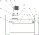
图1为本实用新型结构示意图;Fig. 1 is the structural representation of the utility model;
图2为本实用新型俯视图;Fig. 2 is the top view of the utility model;
图3为本实用新型上胶条机构结构示意图;Fig. 3 is the structural schematic diagram of the glue strip mechanism of the present invention;
图4为本实用新型出胶条头结构示意图;Fig. 4 is the structural schematic diagram of the glue strip head of the present invention;
图5为图4中A向结构示意图;FIG. 5 is a schematic view of the structure in the direction A in FIG. 4;
图6为本实用新型出胶条头与转轴结构示意图;Fig. 6 is the structural schematic diagram of the glue strip head and the rotating shaft of the present invention;
图7为本实用新型升降机构结构示意图;7 is a schematic structural diagram of the lifting mechanism of the present invention;
图8为本实用新型移动板结构示意图;8 is a schematic structural diagram of the mobile board of the present invention;
图9为本实用新型支撑柱结构示意图。FIG. 9 is a schematic diagram of the structure of the support column of the present invention.
其中,机架1,移动板2,横向工作台3,第一滑轨4,第一动力件5,第一螺杆6,第二滑轨7,第二动力件8,第二螺杆9,纵向移动架10,升降板11,支架12,第三动力件13,第三螺杆14,支撑杆15,开卷辊16,绕线盘17,第四动力件18,锥齿轮组19,转轴20,转轮21,通孔22,出胶条孔23,挡轮24,出胶条头25,隔离纸槽26,翻转台27,固定轴28,第五动力件29,支撑柱30,顶柱31,磁扣32,气缸33,翻转轴34,插入部35,插入杆36,锁紧母37,气动剪刀38,胶条39,隔离纸40。Among them, the frame 1, the moving plate 2, the horizontal table 3, the first slide rail 4, the first power member 5, the first screw 6, the second slide rail 7, the second power member 8, the second screw 9, the longitudinal The moving
具体实施方式Detailed ways
下面将结合本实用新型实施例中的附图,对本实用新型实施例中的技术方案进行清楚、完整地描述,显然,所描述的实施例仅仅是本实用新型一部分实施例,而不是全部的实施例。基于本实用新型中的实施例,本领域普通技术人员在没有做出创造性劳动前提下所获得的所有其他实施例,都属于本实用新型保护的范围。The technical solutions in the embodiments of the present utility model will be clearly and completely described below with reference to the accompanying drawings in the embodiments of the present utility model. Obviously, the described embodiments are only a part of the embodiments of the present utility model, rather than all the implementations. example. Based on the embodiments of the present invention, all other embodiments obtained by those of ordinary skill in the art without creative work fall within the protection scope of the present invention.
为使本实用新型的上述目的、特征和优点能够更加明显易懂,下面结合附图和具体实施方式对本实用新型作进一步详细的说明。In order to make the above objects, features and advantages of the present utility model more clearly understood, the present utility model will be described in further detail below with reference to the accompanying drawings and specific embodiments.
参考图1-9所示,本实用新型提供一种胶条粘接机,包括机架1,机架1上滑动连接有移动工作台,机架1上连接有翻转台27,移动工作台包括移动板2,移动板2上滑动连接有纵向工作台,纵向工作台上螺纹连接有升降机构,纵向工作台上固定有开卷机构,纵向工作台上转动连接有上胶条机构。Referring to Figures 1-9, the present utility model provides an adhesive tape bonding machine, comprising a frame 1, a mobile worktable is slidably connected to the frame 1, a turning table 27 is connected to the frame 1, and the mobile worktable includes The moving plate 2 is slidably connected with a longitudinal worktable, a lifting mechanism is threadedly connected to the longitudinal worktable, an unwinding mechanism is fixed on the longitudinal worktable, and a gluing strip mechanism is rotatably connected to the longitudinal worktable.
进一步优化方案,机架1上设有横向工作台3,横向工作台3上设有第一滑轨4,在移动板2上设有与第一滑轨4适配的凹槽,实现第一滑轨4与移动板2滑动连接,机架1上固定有第一动力件5,第一动力件5连接第一螺杆6,第一螺杆6螺纹连接移动板2,第一动力件5优选为电机,第一螺杆6与第一滑轨4平行设置,在第一动力件5的带动下第一螺杆6带动移动板2做直线运动。To further optimize the solution, the frame 1 is provided with a
进一步优化方案,移动板2上设有第二滑轨7,第二滑轨7滑动连接纵向工作台,移动板2上固定有第二动力件8,第二动力件8为电机,第二动力件8固定连接第二螺杆9,第二螺杆9螺纹连接纵向工作台,第二动力件8带动第二螺杆9转动,使纵向工作台做直线运动。To further optimize the solution, the moving plate 2 is provided with a second sliding rail 7, the second sliding rail 7 is slidably connected to the longitudinal table, the moving plate 2 is fixed with a second power member 8, the second power member 8 is a motor, and the second power member 8 is a motor. The second screw 9 is fixedly connected to the second screw 9, and the second screw 9 is threadedly connected to the longitudinal table. The second power element 8 drives the second screw 9 to rotate, so that the longitudinal table moves linearly.
进一步优化方案,纵向工作台包括纵向移动架10和升降板11,纵向移动架10与升降板11无固定,纵向移动架10上设有与第二滑轨7适应的凹槽,实现纵向移动架10与第二滑轨7的滑动连接,升降板11与升降机构螺纹连接。To further optimize the solution, the longitudinal workbench includes a longitudinal moving
进一步优化方案,升降机构包括支架12,支架12与移动架10固定连接,支架12上固定连接有第三动力件13,第三动力件13,为电机,第三动力件13固定连接有第三螺杆14,第三螺杆14与升降板11螺纹连接,第三动力件13启动带动第三螺杆14转动使升降板11在第三螺杆14的轴向方向上下运动。To further optimize the solution, the lifting mechanism includes a
进一步优化方案,开卷机构包括与升降板11固定连接的支撑杆15,支撑杆15上插入固定有开卷辊16,开卷辊16端部螺纹连接螺母,开卷辊16上用于放置绕线盘17,开卷辊16上放置绕线盘17后通过螺母锁紧,防止绕线盘17脱出。To further optimize the solution, the uncoiler mechanism includes a
进一步优化方案,上胶条机构包括与升降板11固定连接的第四动力件18,第四动力件18为电机,第四动力件18通过锥齿轮组19连接有转轴20,锥齿轮组为相互啮合的两个锥齿轮,转轴20一端固定有转轮21,转轮21为两个,胶条39处于两个转轮21的中间位置,转轴20另一端可拆卸连接有出胶条头25,转轴20上设有通孔22,出胶条头25上设有出胶条孔23,通孔22与出胶条孔23贯通设置,出胶条头25端部设有挡轮24,出胶条头25上设有隔离纸槽26,出胶条孔23与隔离纸槽26相贯通。To further optimize the solution, the glue strip mechanism includes a
更进一步的说,转轴20端部设有插入部35,在插入部35和出胶条头25上设有插入插入杆36的通孔,并且插入杆36两端螺纹连接锁紧母37,插入部35插入到出胶条头25内,然后插入插入杆36后锁紧母37进行锁紧。Furthermore, the end of the rotating
进一步优化方案,翻转台27一端套接有固定轴28,翻转台27另一端固定连接有翻转轴34,固定轴28与机架1固定连接,翻转轴34固定有第五动力件29,第五动力件29与机架1固定连接,第五动力件29为电机,第五动力件29带动翻转轴34转动使翻转台27进行翻转。To further optimize the solution, one end of the turning table 27 is sleeved with a
进一步优化方案,翻转台27上设有若干个定位部,定位部包括支撑柱30,支撑柱30与翻转台27固定,支撑柱30内套接有顶柱31,顶柱31一端设有磁扣32,磁扣32与前围钣金件相吸合,顶柱31另一端固定有气缸33,气缸33固定在翻转台27上。To further optimize the solution, the overturning table 27 is provided with a number of positioning portions, the positioning portion includes a
进一步优化方案,在翻转轴34上固定有气动剪刀38,用于胶条39的剪断。In a further optimized solution,
进一步优化方案,本胶条粘接机通过PLC进行自动控制,具体型号为jahw201701,首先把EPDM胶条39穿入到出胶条头25最前端,并且隔离纸40与胶条39进行剥开,前围钣金件放置到翻转台27上,磁扣32与前围钣金件进行吸合,然后启动气缸33带动顶柱31插入到前围钣金件的固定孔内进行固定,然后通过PLC预设好的运行轨迹进行粘接胶条39,胶条39粘接完成,出胶条头25回原点,前围钣金件取出。原有需要8个人粘接,每人粘接一件需要2分钟,现胶条粘接机仅需1人操作,20-30秒粘接一件,粘接速度快,效率高,一致性好。To further optimize the plan, this adhesive tape bonding machine is automatically controlled by PLC. The specific model is jahw201701. First, the EPDM
在本实用新型的描述中,需要理解的是,术语“纵向”、“横向”、“上”、“下”、“前”、“后”、“左”、“右”、“竖直”、“水平”、“顶”、“底”、“内”、“外”等指示的方位或位置关系为基于附图所示的方位或位置关系,仅是为了便于描述本实用新型,而不是指示或暗示所指的装置或元件必须具有特定的方位、以特定的方位构造和操作,因此不能理解为对本实用新型的限制。In the description of the present invention, it should be understood that the terms "portrait", "horizontal", "upper", "lower", "front", "rear", "left", "right", "vertical" , "horizontal", "top", "bottom", "inside", "outside" and other indications of orientation or positional relationship are based on the orientation or positional relationship shown in the accompanying drawings, only for the convenience of describing the present utility model, not Indicates or implies that the referred device or element must have a particular orientation, be constructed and operate in a particular orientation, and therefore should not be construed as a limitation of the present invention.
以上所述的实施例仅是对本实用新型的优选方式进行描述,并非对本实用新型的范围进行限定,在不脱离本实用新型设计精神的前提下,本领域普通技术人员对本实用新型的技术方案做出的各种变形和改进,均应落入本实用新型权利要求书确定的保护范围内。The above-mentioned embodiments are only to describe the preferred mode of the present invention, and do not limit the scope of the present invention. Under the premise of not departing from the design spirit of the present invention, those of ordinary skill in the art can make the technical solutions of the present invention. Various deformations and improvements made shall fall within the protection scope determined by the claims of the present utility model.
Claims (10)
Priority Applications (1)
| Application Number | Priority Date | Filing Date | Title |
|---|---|---|---|
| CN202020233601.8U CN211807857U (en) | 2020-03-02 | 2020-03-02 | A glue sticking machine |
Applications Claiming Priority (1)
| Application Number | Priority Date | Filing Date | Title |
|---|---|---|---|
| CN202020233601.8U CN211807857U (en) | 2020-03-02 | 2020-03-02 | A glue sticking machine |
Publications (1)
| Publication Number | Publication Date |
|---|---|
| CN211807857U true CN211807857U (en) | 2020-10-30 |
Family
ID=72996853
Family Applications (1)
| Application Number | Title | Priority Date | Filing Date |
|---|---|---|---|
| CN202020233601.8U Active CN211807857U (en) | 2020-03-02 | 2020-03-02 | A glue sticking machine |
Country Status (1)
| Country | Link |
|---|---|
| CN (1) | CN211807857U (en) |
Cited By (1)
| Publication number | Priority date | Publication date | Assignee | Title |
|---|---|---|---|---|
| CN111186130A (en) * | 2020-03-02 | 2020-05-22 | 保定市宏腾科技有限公司 | A glue sticking machine |
-
2020
- 2020-03-02 CN CN202020233601.8U patent/CN211807857U/en active Active
Cited By (2)
| Publication number | Priority date | Publication date | Assignee | Title |
|---|---|---|---|---|
| CN111186130A (en) * | 2020-03-02 | 2020-05-22 | 保定市宏腾科技有限公司 | A glue sticking machine |
| CN111186130B (en) * | 2020-03-02 | 2024-07-19 | 保定市宏腾科技有限公司 | Adhesive tape bonding machine |
Similar Documents
| Publication | Publication Date | Title |
|---|---|---|
| CN204642354U (en) | High precision automatic wire labeling equipment | |
| CN106586663A (en) | Automatic Adhesive Laminating Machine | |
| CN111186130B (en) | Adhesive tape bonding machine | |
| CN216235084U (en) | Coiling mechanism is used in production of non-setting adhesive label | |
| CN219730068U (en) | Rubber coating machine | |
| CN217753101U (en) | A label laminating machine | |
| CN211807858U (en) | A mobile workbench of a glue strip bonding machine | |
| CN206426537U (en) | A kind of automatic viscose glue edge banding machine | |
| CN211807859U (en) | An overturning table of a glue strip bonding machine | |
| CN221874425U (en) | Automatic film wrapping machine | |
| CN209113169U (en) | A kind of electroplating strip mobile winding car | |
| CN223972808U (en) | Four-axis pad pasting device of cell-phone center | |
| CN209242267U (en) | Without shaft-penetrating type automatic material receptacle | |
| CN108000890A (en) | A kind of apparatus and method for pasting mobile phone DOME pieces | |
| CN224062140U (en) | Coiled material automatic blanking mechanism | |
| CN219585424U (en) | Wrapping bag membrane is rolled up coiling mechanism | |
| CN218928896U (en) | Double-layer toughened glass gluing mechanism | |
| CN208561090U (en) | A kind of gauze bandage tape handler of automatic addition core | |
| CN114727490B (en) | Copper foil separating device with horizontal oblique angle rotary push rod | |
| CN220787540U (en) | Aluminum foil unreeling mechanism and unreeling machine thereof | |
| CN212712129U (en) | A glue strip rewinding machine | |
| CN223865993U (en) | An automatic roll changing device for packaging bag production | |
| CN219028577U (en) | Automatic foam laminating machine | |
| CN222373921U (en) | Automatic film rolling machine for industrial RO (reverse osmosis) film | |
| CN220886360U (en) | Auxiliary winding device of rewinder |
Legal Events
| Date | Code | Title | Description |
|---|---|---|---|
| GR01 | Patent grant | ||
| GR01 | Patent grant | ||
| PE01 | Entry into force of the registration of the contract for pledge of patent right | ||
| PE01 | Entry into force of the registration of the contract for pledge of patent right |
Denomination of utility model: A type of adhesive tape bonding machine Effective date of registration: 20230519 Granted publication date: 20201030 Pledgee: Baoding Mancheng District Rural Credit Union Co.,Ltd. Daziying Credit Cooperative Pledgor: BAODING HONGTENG TECHNOLOGY Co.,Ltd. Registration number: Y2023980041170 |
|
| PC01 | Cancellation of the registration of the contract for pledge of patent right | ||
| PC01 | Cancellation of the registration of the contract for pledge of patent right |
Granted publication date: 20201030 Pledgee: Baoding Mancheng District Rural Credit Union Co.,Ltd. Daziying Credit Cooperative Pledgor: BAODING HONGTENG TECHNOLOGY Co.,Ltd. Registration number: Y2023980041170 |