CN211783600U - Environmental monitoring system for hydropower station - Google Patents
Environmental monitoring system for hydropower station Download PDFInfo
- Publication number
- CN211783600U CN211783600U CN202020494793.8U CN202020494793U CN211783600U CN 211783600 U CN211783600 U CN 211783600U CN 202020494793 U CN202020494793 U CN 202020494793U CN 211783600 U CN211783600 U CN 211783600U
- Authority
- CN
- China
- Prior art keywords
- module
- pin
- sensor
- adopts
- monitoring system
- Prior art date
- Legal status (The legal status is an assumption and is not a legal conclusion. Google has not performed a legal analysis and makes no representation as to the accuracy of the status listed.)
- Expired - Fee Related
Links
- 230000007613 environmental effect Effects 0.000 title claims abstract description 23
- 238000012544 monitoring process Methods 0.000 title claims abstract description 23
- XLYOFNOQVPJJNP-UHFFFAOYSA-N water Substances O XLYOFNOQVPJJNP-UHFFFAOYSA-N 0.000 claims abstract description 33
- 238000004891 communication Methods 0.000 claims abstract description 29
- 238000010295 mobile communication Methods 0.000 claims abstract description 21
- 239000003990 capacitor Substances 0.000 description 28
- 238000010586 diagram Methods 0.000 description 7
- 238000005259 measurement Methods 0.000 description 7
- 238000005516 engineering process Methods 0.000 description 6
- 239000013078 crystal Substances 0.000 description 4
- 238000007667 floating Methods 0.000 description 4
- 238000000034 method Methods 0.000 description 4
- 238000011161 development Methods 0.000 description 3
- 230000005540 biological transmission Effects 0.000 description 2
- 238000009529 body temperature measurement Methods 0.000 description 2
- 238000013461 design Methods 0.000 description 2
- 238000012986 modification Methods 0.000 description 2
- 230000004048 modification Effects 0.000 description 2
- 230000035945 sensitivity Effects 0.000 description 2
- 229910000831 Steel Inorganic materials 0.000 description 1
- 239000003985 ceramic capacitor Substances 0.000 description 1
- 238000006243 chemical reaction Methods 0.000 description 1
- 230000008602 contraction Effects 0.000 description 1
- 238000001514 detection method Methods 0.000 description 1
- 229920005994 diacetyl cellulose Polymers 0.000 description 1
- 238000006073 displacement reaction Methods 0.000 description 1
- 238000007689 inspection Methods 0.000 description 1
- 238000012423 maintenance Methods 0.000 description 1
- 238000000691 measurement method Methods 0.000 description 1
- 239000000203 mixture Substances 0.000 description 1
- 230000002093 peripheral effect Effects 0.000 description 1
- 238000012545 processing Methods 0.000 description 1
- 239000000565 sealant Substances 0.000 description 1
- 239000010959 steel Substances 0.000 description 1
- 238000009966 trimming Methods 0.000 description 1
Images


Landscapes
- Arrangements For Transmission Of Measured Signals (AREA)
Abstract
本实用新型涉及一种水电站环境监测系统,包括安装在水电站的信息采集设备以及云服务器,信息采集设备将采集到的信息传输给云服务器;信息采集设备包括单片机模块和供电模块,单片机模块分别连接有水位传感器、雨量传感器、温度探测器、状态灯模块、按键模块、超声波管道流量传感器、串口通信模块、声音传感器、闸门开度仪、WiFi模块、以太网模块、NB‑IOT模块以及移动通信模块。本实用新型可自动采集水电站水位、雨量、温度、流量、闸门开度值、环境声音等信息,并可以通过移动通信模块、NB‑IOT模块、以太网模块和WiFi模块中任一种模块,实现与云端服务器的通信,安全可靠、扩展灵活、适用性强、成本较低。
The utility model relates to an environmental monitoring system for a hydropower station, comprising information collection equipment installed in the hydropower station and a cloud server, the information collection equipment transmits the collected information to the cloud server; the information collection equipment comprises a single chip module and a power supply module, and the single chip modules are respectively connected to There are water level sensor, rain sensor, temperature detector, status light module, button module, ultrasonic pipeline flow sensor, serial communication module, sound sensor, gate opening meter, WiFi module, Ethernet module, NB‑IOT module and mobile communication module . The utility model can automatically collect information such as water level, rainfall, temperature, flow rate, gate opening value, ambient sound, etc. of the hydropower station, and can be realized by any one of a mobile communication module, an NB-IOT module, an Ethernet module and a WiFi module. The communication with the cloud server is safe and reliable, flexible in expansion, strong in applicability and low in cost.
Description
技术领域technical field
本实用新型涉及通信技术领域,具体涉及一种水电站环境监测系统。The utility model relates to the technical field of communication, in particular to an environmental monitoring system of a hydropower station.
背景技术Background technique
水电站大多数建在偏远山区,专业人员少,对水电站的日常维护和安全监测带来不便,传统依靠人工巡视监测的方式已然无法满足当今信息化发展的需求。随着自动化信息技术的飞速发展,自动采集水电站环境信息并传送远程监控中心成为一种新的管理思路,在对水电站环境指标进行采集分析时,除了关注环境影响因素外,还需要对水电站的水位、流量进行重点监控,以确保水电站能够安全可靠的运行,通过所采集到的指标进行综合分析,实现水电站的闸门自动开启或关闭控制。Most hydropower stations are built in remote mountainous areas with few professionals, which brings inconvenience to the daily maintenance and safety monitoring of hydropower stations. The traditional way of relying on manual inspection and monitoring can no longer meet the needs of today's informatization development. With the rapid development of automated information technology, automatic collection of hydropower station environmental information and transmission to the remote monitoring center has become a new management idea. When collecting and analyzing the environmental indicators of hydropower stations, in addition to paying attention to environmental factors, it is also necessary to monitor the water level of the hydropower station. 3. Focus on monitoring the flow to ensure the safe and reliable operation of the hydropower station. Through comprehensive analysis of the collected indicators, the automatic opening or closing control of the gate of the hydropower station is realized.
实用新型内容Utility model content
本实用新型所提供的水电站环境监测系统,能够自动采集水电站的水位、降雨量、温度、流量、闸门开度值、环境声音等信息,并通过多种通信方式实现可靠的远程信息传输,方便监控中心对水电站的实时监控。The hydropower station environment monitoring system provided by the utility model can automatically collect information such as water level, rainfall, temperature, flow rate, gate opening value, environmental sound, etc. of the hydropower station, and realize reliable remote information transmission through various communication methods, which is convenient for monitoring Real-time monitoring of hydropower stations by the center.
为了实现上述目的,本实用新型所采用的技术方案为:In order to achieve the above-mentioned purpose, the technical scheme adopted by the present utility model is:
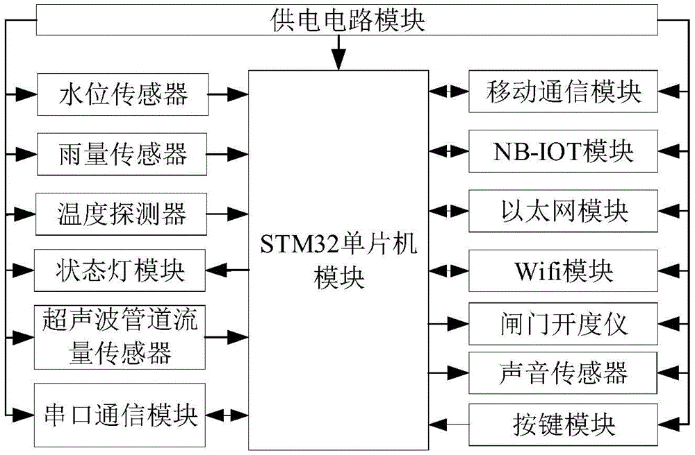
一种水电站环境监测系统,包括安装在水电站的信息采集设备以及云服务器,信息采集设备将采集到的信息传输给云服务器;所述信息采集设备包括单片机模块和供电模块,单片机模块分别连接有水位传感器、雨量传感器、温度探测器、状态灯模块、按键模块、超声波管道流量传感器、串口通信模块、声音传感器、闸门开度仪、WiFi模块、以太网模块、NB-IOT模块以及移动通信模块。An environmental monitoring system for a hydropower station, comprising information collection equipment installed in the hydropower station and a cloud server, the information collection equipment transmits the collected information to the cloud server; the information collection equipment comprises a single chip module and a power supply module, and the single chip modules are respectively connected with water level Sensor, rain sensor, temperature detector, status light module, button module, ultrasonic pipeline flow sensor, serial communication module, sound sensor, gate opening meter, WiFi module, Ethernet module, NB-IOT module and mobile communication module.
可选地,所述单片机模块采用STM32F107C8T6芯片。Optionally, the single-chip microcomputer module adopts STM32F107C8T6 chip.
可选地,所述WiFi模块采用BCM4322芯片,所述NB-IOT模块采用BC95模块,所述移动通信模块采用EC20 Mini PCIe模块,所述以太网模块采用W5500芯片。Optionally, the WiFi module adopts a BCM4322 chip, the NB-IOT module adopts a BC95 module, the mobile communication module adopts an EC20 Mini PCIe module, and the Ethernet module adopts a W5500 chip.
可选地,所述水位传感器采用Water Sensor水位传感器模块。Optionally, the water level sensor adopts a Water Sensor water level sensor module.
可选地,所述雨量传感器采用JDZ05-1模块。Optionally, the rain sensor adopts JDZ05-1 module.
可选地,所述超声波管道流量传感器采用TDS-100F模块。Optionally, the ultrasonic pipeline flow sensor adopts a TDS-100F module.
可选地,所述闸门开度仪采用SDM201闸位开度仪。Optionally, the gate opening degree meter adopts SDM201 gate opening degree meter.
可选地,所述声音传感器采用Sound Detector模块。Optionally, the sound sensor adopts a Sound Detector module.
可选地,所述温度探测器采用DS18B20温度传感器模块。Optionally, the temperature detector adopts a DS18B20 temperature sensor module.
可选地,所述供电模块使用RT9193-33芯片。Optionally, the power supply module uses an RT9193-33 chip.
本实用新型通过水位传感器、雨量传感器、温度传感器、超声波管道流量传感器、闸门开度仪、声音传感器等传感器采集水位、雨量、温度、流量、闸门开度值、环境声音等信息,并可以通过移动通信模块、NB-IOT模块、以太网模块和WiFi模块中任一种模块,实现与云端服务器的通信,安全可靠;本实用新型可采集多种水电站环境数据,且提供与云端服务器的多种可选的通信方式,具有结构简单、扩展灵活、适用性强、成本较低等特点。The utility model collects information such as water level, rainfall, temperature, flow, gate opening value, ambient sound and other information through sensors such as water level sensor, rain sensor, temperature sensor, ultrasonic pipeline flow sensor, gate opening meter, sound sensor, etc. Any one of the communication module, the NB-IOT module, the Ethernet module and the WiFi module can realize the communication with the cloud server, which is safe and reliable; the utility model can collect a variety of environmental data of the hydropower station, and provides a variety of possibilities to communicate with the cloud server. The selected communication method has the characteristics of simple structure, flexible expansion, strong applicability and low cost.
附图说明Description of drawings
图1为本实用新型实施例中信息采集设备的外部结构示意图;1 is a schematic diagram of the external structure of an information collection device in an embodiment of the present utility model;
图2为本实用新型实施例中信息采集设备的内部结构示意图;2 is a schematic diagram of the internal structure of an information collection device in an embodiment of the present invention;
图3为本实用新型实施例中信息采集设备的结构原理框图;Fig. 3 is the structural principle block diagram of the information collection device in the embodiment of the present utility model;
图4是信息采集设备中STM32处理器模块的电路原理图;Fig. 4 is the circuit schematic diagram of the STM32 processor module in the information acquisition equipment;
图5是信息采集设备中供电电路模块的电路原理图;Fig. 5 is the circuit schematic diagram of the power supply circuit module in the information acquisition equipment;
图6是信息采集设备中WiFi模块接口、NB-IOT模块接口、以太网模块接口、串口通信模块接口和移动通信模块接口的电路原理图;Fig. 6 is the circuit schematic diagram of WiFi module interface, NB-IOT module interface, Ethernet module interface, serial communication module interface and mobile communication module interface in the information collection device;
图7是信息采集设备中按键模块、状态灯模块、超声波管道流量传感器接口、温度探测器接口、水位传感器接口、声音传感器接口、闸门开度仪接口和雨量传感器接口的电路原理图;Fig. 7 is the circuit schematic diagram of the button module, the status light module, the ultrasonic pipeline flow sensor interface, the temperature detector interface, the water level sensor interface, the sound sensor interface, the gate opening meter interface and the rain sensor interface in the information acquisition equipment;
图中:In the picture:
1-WiFi模块,2-NB-IOT模块,3-移动通信模块,4-供电电路模块,5-STM32单片机模块,6-状态灯模块,7-按键模块,8-声音传感器,9-水位传感器,10-雨量传感器,11-超声波管道流量传感器,12-设备外壳,13-串口通信模块,14-温度探测器,15-闸门开度仪,16-以太网模块。1-WiFi module, 2-NB-IOT module, 3-mobile communication module, 4-power supply circuit module, 5-STM32 microcontroller module, 6-status light module, 7-button module, 8-sound sensor, 9-water level sensor , 10-rain sensor, 11-ultrasonic pipeline flow sensor, 12-equipment shell, 13-serial communication module, 14-temperature detector, 15-gate opening meter, 16-Ethernet module.
具体实施方式Detailed ways
下面将结合本实用新型实施例中的附图,对本实用新型实施例中的技术方案进行清楚、完整地描述。The technical solutions in the embodiments of the present invention will be clearly and completely described below with reference to the accompanying drawings in the embodiments of the present invention.
本实施例公开一种水电站环境监测系统,主要包括信息采集设备以及云服务器,信息采集设备安装在水电站,将采集到的数据传输给云服务器。信息采集设备如图1至图7所示,包括设备外壳12,设备外壳12上设有用于选择通信方式的按键模块7、用于显示工作状态的状态灯模块6、用于测量水位高度的水位传感器9、用于测量降雨情况的雨量传感器10、用于连接声波管道流量传感器的超声波管道流量传感器11、用于实时获取闸门开度信息的闸门开度仪15、用于采集机组和环境的声音信号的声音传感器8、用于实现串口通信的串口通信模块13、用于采集周围环境温度的温度探测器14以及用于实现以太网通信的以太网模块16。设备外壳12内设有STM32单片机模块5、用于实现移动通信的移动通信模块3、用于实现窄带物联网通信的NB-IOT模块2、用于实现无线局域网通信的WiFi模块1和用于提供模块电源的供电电路模块4。This embodiment discloses an environmental monitoring system for a hydropower station, which mainly includes an information collection device and a cloud server. The information collection device is installed in the hydropower station and transmits the collected data to the cloud server. As shown in Figures 1 to 7, the information collection device includes a
STM32单片机模块5分别与水位传感器9、雨量传感器10、温度探测器14、状态灯模块6、超声波管道流量传感器11、串口通信模块13、按键模块7、声音传感器8、闸门开度仪15、WiFi模块1、以太网模块16、NB-IOT模块2和移动通信模块3连接。供电电路模块4分别与水位传感器9、雨量传感器10、温度探测器14、状态灯模块6、超声波管道流量传感器11、串口通信模块13、按键模块7、声音传感器8、闸门开度仪15、WiFi模块1、以太网模块16、NB-IOT模块2、移动通信模块3和STM32单片机模块5连接。
STM32单片机模块5采用STM32F407ZGT6芯片。STM32F407ZGT6芯片的工作频率高达168MHz,具有浮点单元(FPU)单精度,支持所有ARM单精度数据处理指令和数据类型。同时高达4KB的备用SRAM以及连接到两条APB总线的各种增强型I/O和外设,并提供三个12位ADC,两个DAC,一个低功耗RTC,十二个通用16位定时器。
WiFi模块1采用BCM4322芯片。BCM4322芯片是Broadcom公司的无线LAN芯片,是第二代Intensi-fi技术,它和IEEE 802.11n draft 2.0标准兼容。最大数据速率可达300Mbps,实际吞吐量超过200Mbps,且集成了802.11媒体接入控制器(MAC)。
NB-IOT模块2采用BC95模块。BC95模块支持900MHz单个频段,且预留了ESIM位置,使用较便利。BC95模块的管脚设计与移远的GPRS模块M35兼容,方便客户设计。NB-
移动通信模块采用EC20 Mini PCIe模块。EC20 Mini PCIe模块包含EC20MiniPCIe-A和EC20 Mini PCIe-E版本,能够向后兼容现存的EDGE和GSM/GPRS网络,以确保在缺乏3G和4G网络的偏远地区也能正常工作。EC20 Mini PCIe模块支持接收分集技术,可实现优质可靠的无线连接,可通过多输入多输出技术(MIMO)降低误码率,改善通信质量,且集成了高速无线连接与内置多星座高精度定位SPS+GLONASS接收器。The mobile communication module adopts EC20 Mini PCIe module. EC20 Mini PCIe modules include EC20MiniPCIe-A and EC20 Mini PCIe-E versions, which are backward compatible with existing EDGE and GSM/GPRS networks to ensure normal operation in remote areas lacking 3G and 4G networks. EC20 Mini PCIe module supports receive diversity technology, which can realize high-quality and reliable wireless connection, can reduce bit error rate and improve communication quality through multiple-input multiple-output technology (MIMO), and integrate high-speed wireless connection and built-in multi-constellation high-precision positioning SPS +GLONASS receiver.
以太网模块16采用W5500芯片。W5500芯片是一款集成全硬件TCP/IP协议栈的嵌入式以太网控制器,具有各路通信互不影响的8个独立硬件Socket,且低功耗,工作电压3.3V,具有简单、快速、稳定、安全的特点。The Ethernet
温度探测器14采用DS18B20温度传感器模块。DS18B20温度传感器模块采用美国Dallas数字化温度传感器DS18B20,采用导热性高的密封胶灌封,保证了温度传感器的高灵敏性,具有较小的温度延迟。该温度传感器模块支持“一线总线”接口,测温范围在-55℃~+125℃,在-10℃~+85℃范围内,精度为±0.5℃。现场温度直接以“一线总线”的数字方式传输,提高了系统的抗干扰性,适合于恶劣环境的现场温度测量。The
水位传感器9采用Water Sensor水位传感器模块。Water Sensor水位传感器模块是一款简单易用、较高的水位识别检测传感器,其通过暴露平行导线的线迹,测量水滴和水量大小从而判断水位。可轻松完成水量到模拟信号的转换,输出的模拟值可直接被开发板读取,具有低功耗和高灵敏度的特点。The
雨量传感器10采用JDZ05-1模块。JDZ05-1模块承雨口内径为Φ200+0.60,外刃口角度为45°,仪器分辨力在0.5mm~0.2mm,降雨强度测量范围为0.01~4mm/min,在0.01~4mm/min雨强范围内,翻斗计量误差为≤±4%。
超声波管道流量传感器11采用TDS-100F模块。TDS-100F模块采用时差式测量方式,低电压,多脉冲,测量周期500ms,准确度为±1%,重复性为±0.5%,电流输出范围为0~20mA,可输入5路电流信号,可输出近20种源信号。The ultrasonic
闸门开度仪15采用SDM201闸位开度仪。SDM201闸位开度仪是闸门开度测量的专用设备,它集测量、显示、控制、通讯为一体,适用于各种水闸。采用“HL-3恒力数字式传感器”,位移测量的钢带跟踪闸门运动,自动伸缩无需其它附加装置。电源功耗小,电源输入DC24V,测量范围在0-80m,分辨率为1mm。The gate
声音传感器8采用Sound Detector模块。Sound Detector模块是一款简单易用、小巧轻便、性价比较高的声音传感器,是由一个小型驻极体麦克风和运算放大器构成,工作电压为2.7V-5.5V。The
供电电路模块4使用RT9193-33芯片。RT9193-33芯片采用CMOS工艺生产的低压差LDO电压调整器。其内部还包括参考电压源电路,误差放大器电路,过流保护电路和相位补偿电路,同时由于利用激光微调技术,实现在输出电压在0.8-5.0V范围内,以0.05V为间隔自由选择。并且芯片具有低功耗和低压差等优点,能够兼容低ESR的陶瓷电容。Power
上述各个模块之间的电连接关系具体说明如下:The electrical connection relationship between the above modules is described in detail as follows:
如图4所示,STM32处理器模块电路:STM32F407ZGT6芯片U5的110脚与WiFi模块接口U4的1脚连接,117脚与WiFi模块接口U4的2脚连接,115脚与WiFi模块接口U4的3脚,114脚与WiFi模块接口U4的4脚连接。STM32F407ZGT6芯片U5的104脚与NB-IOT模块接口PNB1的1脚连接,101脚与NB-IOT模块接口PNB1的3脚连接,102脚与NB-IOT模块接口PNB1的4脚连接,2脚与NB-IOT模块接口PNB1的5脚连接,132脚与NB-IOT模块接口PNB1的6脚连接。STM32F407ZGT6芯片U5的25脚与以太网模块接口YTW1的3脚连接,27脚与以太网模块接口YTW1的4脚连接,28脚与以太网模块接口YTW1的7脚连接,29脚与以太网模块接口YTW1的8脚连接,49脚与以太网模块接口YTW1的9脚连接。STM32F407ZGT6芯片U5的135脚与串口通信模块接口P4的1脚连接,69脚与串口通信模块接口P4的3脚连接,70脚与串口通信模块接口P4的4脚连接。STM32F407ZGT6芯片U5的112脚与移动通信模块接口EC1的6脚,111脚与移动通信模块接口EC1的7脚连接,116脚与移动通信模块接口EC2的18脚连接,113脚与移动通信模块接口EC2的19脚连接,6脚与移动通信模块接口EC2的20脚连接。STM32F407ZGT6芯片U5的34脚连接与按键模块的开关按键一端连接。STM32F407ZGT6芯片U5的134脚与状态灯模块的R1电阻一端连接。STM32F407ZGT6芯片U5的119脚与超声波管道流量传感器接口P1的2脚连接,122脚与超声波管道流量传感器接口P1的3脚连接。STM32F407ZGT6芯片U5的124脚与温度探测器接口U2的3脚连接。STM32F407ZGT6芯片U5的22脚与水位传感器接口W1的2脚连接。STM32F407ZGT6芯片U5的40脚与声音传感器接口P3的1脚连接,43脚与声音传感器接口P3的2脚连接。STM32F407ZGT6芯片U5的77脚与闸门开度仪接口P5的2脚连接,78脚与闸门开度仪接口P5的3脚连接。STM32F407ZGT6芯片U5的41脚与雨量传感器接口P2的3脚连接,42脚与闸门开度仪接口P5的4脚连接。STM32F407ZGT6芯片U5的9脚均与晶振Y1的一端和电容C6的一端连接。STM32F407ZGT6芯片U5的8脚均与晶振Y1的另一端和电容C5的一端连接。电容C5的另一端与电容C6的另一端连接,且接地。STM32F407ZGT6芯片U5的6脚均与二极管D1的负极,二极管D2的负极和电容C9的一端连接。二极管D1的另一端与二极管D2的另一端连接,且与电池BAT的正极连接。电容C9的另一端与电池BAT的负极连接。STM32F407ZGT6芯片U5的24脚均与晶振Y2的一端,电阻R5的一端和电容C11的一端连接。STM32F407ZGT6芯片U5的23脚均与晶振Y2的另一端,电阻R5的另一端和电容C12的一端连接。电容C11的另一端与电容C12的另一端连接,且接地。STM32F407ZGT6芯片U5的71脚与电容C18连接。STM32F407ZGT6芯片U5的106脚与电容C17连接。电容C18的另一端与电容C17的另一端连接,且接地。STM32F407ZGT6芯片U5的33脚均与电容C8的一端,电容C10的一端和电阻R6的一端连接。STM32F407ZGT6芯片U5的31脚均与电容C8的另一端和电容C10的另一端连接和电阻R4的一端连接。STM32F407ZGT6芯片U5的143脚与电阻R3的一端,电阻R4的另一端连接。电阻R3的另一端接地。As shown in Figure 4, STM32 processor module circuit: STM32F407ZGT6
如图5所示,供电电路模块:RT9193-33芯片U1的1脚均与U1的3脚,电容C1的一端,接口USB的1脚连接,并提供+5V电源电压。电容C1的另一端接地。RT9193-33芯片U1的2脚接地。RT9193-33芯片U1的4脚与电容C4的一端连接。电容C4的另一端接地。RT9193-33芯片U1的5脚均与电容C2,电容C3的一端连接,且提供+3.3V直流电源。电容C2与电容C3的另一端相互连接,且接地。接口USB的2-4脚悬空,5脚接地。As shown in Figure 5, power supply circuit module: RT9193-33
如图6所示,WiFi模块接口、NB-IOT模块接口、以太网模块接口、串口通信模块接口和移动通信模块接口电路:WiFi模块接口U4的1脚与STM32F407ZGT6芯片U5的110脚连接,2脚与STM32F407ZGT6芯片U5的117脚连接,3脚与STM32F407ZGT6芯片U5的115脚连接,4脚与STM32F407ZGT6芯片U5的114脚连接,5脚接地,6脚外接+3.3V直流电源。NB-IOT模块接口PNB1的1脚与STM32F407ZGT6芯片U5的104脚连接,2脚悬空,3脚与STM32F407ZGT6芯片U5的101脚连接,4脚与STM32F407ZGT6芯片U5的102脚连接,5脚与STM32F407ZGT6芯片U5的2脚连接,6脚与STM32F407ZGT6芯片U5的132脚连接,7脚外接+3.3V直流电源,8脚接地。以太网模块接口YTW1的1脚悬空,2脚接地,3脚与STM32F407ZGT6芯片U5的25脚连接,4脚与STM32F407ZGT6芯片U5的27脚连接,5脚悬空,6脚外接+3.3V直流电源,7脚与STM32F407ZGT6芯片U5的28脚连接,8脚与STM32F407ZGT6芯片U5的29脚连接,9脚与STM32F407ZGT6芯片U5的49脚连接,10脚悬空。串口通信模块接口P4的1脚与STM32F407ZGT6芯片U5的135脚连接,2脚悬空,3脚与STM32F407ZGT6芯片U5的69脚连接,4脚与STM32F407ZGT6芯片U5的70脚连接,5脚外接+3.3V直流电源,6脚接地。移动通信模块接口EC1与EC2的1-5脚悬空,6脚与STM32F407ZGT6芯片U5的112脚连接,7脚与STM32F407ZGT6芯片U5的111脚连接,8-9脚悬空,10脚外接+3.3V直流电源,11脚悬空,12脚接地,13-17脚悬空,18脚与STM32F407ZGT6芯片U5的116脚连接,19脚与STM32F407ZGT6芯片U5的113脚连接,20脚与STM32F407ZGT6芯片U5的6脚连接,21脚悬空,22-23脚外接+3.3V直流电源。As shown in Figure 6, WiFi module interface, NB-IOT module interface, Ethernet module interface, serial communication module interface and mobile communication module interface circuit: 1 pin of WiFi module interface U4 is connected to 110 pin of STM32F407ZGT6 chip U5, 2 pin It is connected to pin 117 of U5 of STM32F407ZGT6 chip,
如图7所示,按键模块、状态灯模块、超声波管道流量传感器接口、温度探测器接口、水位传感器接口、声音传感器接口、闸门开度仪接口和雨量传感器接口电路:按键模块的开关按键一端与STM32F407ZGT6芯片U5的34脚连接,且另一端外接+3.3V直流电源。状态灯模块的电阻R1一端与STM32F407ZGT6芯片U5的134脚连接。状态灯模块的电阻R1另一端与发光二极管的负极连接。状态灯模块的发光二极管的正极外接+3.3V直流电源。超声波管道流量传感器接口P1的1脚外接+3.3V直流电源,2脚与STM32F407ZGT6芯片U5的119脚连接,3脚与STM32F407ZGT6芯片U5的122脚连接,4脚接地。温度探测器接口U2的1-2脚接地,3脚与STM32F407ZGT6芯片U5的124脚链接,且连接电阻R2的一端,4脚与电阻R2另一端,电容C5的一端连接,且外接+3.3V直流电源。温度探测器接口的电容C5另一端接地。所述水位传感器接口W1的0脚接地,1脚外接+3.3V直流电源,2脚与STM32F407ZGT6芯片U5的22脚连接。所述声音传感器接口P3的1脚与STM32F407ZGT6芯片U5的40脚连接,2脚与STM32F407ZGT6芯片U5的43脚连接,3脚接地,4脚外接+3.3V直流电源。所述闸门开度仪接口P5的1脚外接+3.3V直流电源,2脚与STM32F407ZGT6芯片U5的77脚连接,3脚与STM32F407ZGT6芯片U5的78脚连接,4脚接地。所述雨量传感器接口P2的1脚外接+3.3V直流电源,2脚接地,3脚与STM32F407ZGT6芯片U5的41脚连接,4脚与STM32F407ZGT6芯片U5的42脚连接。As shown in Figure 7, the key module, the status light module, the ultrasonic pipeline flow sensor interface, the temperature detector interface, the water level sensor interface, the sound sensor interface, the gate opening meter interface and the rain sensor interface circuit: one end of the switch key of the key module is connected to Pin 34 of STM32F407ZGT6 chip U5 is connected, and the other end is connected to a +3.3V DC power supply. One end of the resistor R1 of the status light module is connected to pin 134 of U5 of the STM32F407ZGT6 chip. The other end of the resistor R1 of the status light module is connected to the negative electrode of the light emitting diode. The positive pole of the LED of the status light module is connected to a +3.3V DC power supply. The 1 pin of the ultrasonic pipeline flow sensor interface P1 is connected to a +3.3V DC power supply, the 2 pin is connected to the 119 pin of the STM32F407ZGT6 chip U5, the 3 pin is connected to the 122 pin of the STM32F407ZGT6 chip U5, and the 4 pin is grounded. The 1-2 pins of the temperature detector interface U2 are grounded, the 3 pin is connected to the 124 pin of the STM32F407ZGT6 chip U5, and is connected to one end of the resistor R2, the 4 pin is connected to the other end of the resistor R2, and one end of the capacitor C5 is connected, and an external +3.3V DC power supply. The other end of the capacitor C5 of the temperature detector interface is grounded. The 0 pin of the water level sensor interface W1 is grounded, the 1 pin is connected to a +3.3V DC power supply, and the 2 pin is connected to the 22 pin of the STM32F407ZGT6 chip U5.
本实用新型的水电站环境监测系统中所采用的各个功能模块均为现有技术已有的硬件设备,本实用新型仅保护水电站环境特性信息采集设备的结构、组成和各个组成部分的连接关系,而不涉及任何软件方法的改进。Each functional module adopted in the hydropower station environmental monitoring system of the present invention is the existing hardware equipment in the prior art, and the present utility model only protects the structure, composition and connection relationship of each component of the hydropower station environmental characteristic information collection equipment, and No software method improvements are involved.
本实用新型的水电站环境监测系统,通过水位传感器、雨量传感器、温度传感器、超声波管道流量传感器、闸门开度仪、声音传感器等传感器采集水位、雨量、温度、流量、闸门开度值、环境声音等信息,并可以通过移动通信模块、NB-IOT模块、以太网模块和WiFi模块中任一种模块,实现与云端服务器的通信;本实用新型可采集多种水电站环境数据,且提供与云端服务器的多种可选的通信方式,具有结构简单、扩展灵活、适用性强、成本较低等特点。The hydropower station environment monitoring system of the utility model collects water level, rainfall, temperature, flow rate, gate opening value, ambient sound, etc. information, and can communicate with the cloud server through any one of the mobile communication module, the NB-IOT module, the Ethernet module and the WiFi module; the utility model can collect a variety of hydropower station environmental data, and provide communication with the cloud server. A variety of optional communication methods have the characteristics of simple structure, flexible expansion, strong applicability, and low cost.
尽管已经示出和描述了本实用新型的实施例,对于本领域的普通技术人员而言,可以理解在不脱离本实用新型的原理和精神的情况下可以对这些实施例进行多种变化、修改、替换和变型,本实用新型的范围由所附权利要求及其等同物限定。Although the embodiments of the present invention have been shown and described, it will be understood by those skilled in the art that various changes and modifications can be made to these embodiments without departing from the principles and spirit of the present invention , alternatives and modifications, the scope of the present invention is defined by the appended claims and their equivalents.
Claims (10)
Priority Applications (1)
| Application Number | Priority Date | Filing Date | Title |
|---|---|---|---|
| CN202020494793.8U CN211783600U (en) | 2020-04-08 | 2020-04-08 | Environmental monitoring system for hydropower station |
Applications Claiming Priority (1)
| Application Number | Priority Date | Filing Date | Title |
|---|---|---|---|
| CN202020494793.8U CN211783600U (en) | 2020-04-08 | 2020-04-08 | Environmental monitoring system for hydropower station |
Publications (1)
| Publication Number | Publication Date |
|---|---|
| CN211783600U true CN211783600U (en) | 2020-10-27 |
Family
ID=72959313
Family Applications (1)
| Application Number | Title | Priority Date | Filing Date |
|---|---|---|---|
| CN202020494793.8U Expired - Fee Related CN211783600U (en) | 2020-04-08 | 2020-04-08 | Environmental monitoring system for hydropower station |
Country Status (1)
| Country | Link |
|---|---|
| CN (1) | CN211783600U (en) |
Cited By (1)
| Publication number | Priority date | Publication date | Assignee | Title |
|---|---|---|---|---|
| CN113079483A (en) * | 2021-03-25 | 2021-07-06 | 广州市地狗灵机环境监测有限公司 | Wireless rainfall sensor system |
-
2020
- 2020-04-08 CN CN202020494793.8U patent/CN211783600U/en not_active Expired - Fee Related
Cited By (2)
| Publication number | Priority date | Publication date | Assignee | Title |
|---|---|---|---|---|
| CN113079483A (en) * | 2021-03-25 | 2021-07-06 | 广州市地狗灵机环境监测有限公司 | Wireless rainfall sensor system |
| CN113079483B (en) * | 2021-03-25 | 2022-06-17 | 广州市地狗灵机环境监测有限公司 | Wireless rainfall sensor system |
Similar Documents
| Publication | Publication Date | Title |
|---|---|---|
| CN207600612U (en) | Intelligent radio temperature sensor based on NB-IoT | |
| CN201417152Y (en) | Portable Multi-parameter Farmland Information Collector | |
| CN102507907A (en) | Novel portable soil moisture monitoring instrument based on GPS (Global Position System)/GPRS (General Packet Radio Service)/GSM (Global System for Mobile Communications) | |
| CN202710176U (en) | Aeolian vibration detecting device for transmission lines | |
| CN105910588A (en) | Intelligent fish lead water depth measurement circuit and method | |
| CN201396150Y (en) | Integrative digital wireless thermoscope | |
| CN205642431U (en) | Power equipment parameter detecting system based on wireless sensor network | |
| CN201707783U (en) | Automatic data acquisition system of concrete cooling through water | |
| CN202041298U (en) | Wireless Temperature Measuring System for Alcoholization of Tobacco Leaves | |
| CN207851571U (en) | An all-in-one sensor device | |
| CN208013129U (en) | A kind of intelligent ozone sensor | |
| CN205537755U (en) | Wireless water quality monitoring device | |
| CN205787182U (en) | A kind of totally digitilized boundary region based on STM32 sonde | |
| CN204694753U (en) | A kind of high-precision transmission line of electricity electric current on-Line Monitor Device | |
| Ji et al. | GPRS-based data real-time transmission system of water-quality monitoring | |
| CN210721829U (en) | Electric power ammeter data acquisition receiver | |
| CN206649653U (en) | A kind of wind field data collecting system | |
| CN208091510U (en) | A kind of multifunctional internet of things gauge table | |
| CN201273823Y (en) | Real-time monitoring device for environmental parameters of power transmission line | |
| CN207764156U (en) | A carbon monoxide concentration monitoring module for wireless sensor network | |
| CN210836526U (en) | A power meter data collector | |
| CN207335778U (en) | Distributed temperature room environmental monitoring system based on wireless sensor technology | |
| CN203053996U (en) | Wind speed and wind direction acquisition device | |
| CN217999572U (en) | Underground low-power-consumption liquid level monitoring terminal and system based on NB-IoT | |
| CN209926541U (en) | A split air conditioner control device based on narrowband Internet of Things |
Legal Events
| Date | Code | Title | Description |
|---|---|---|---|
| GR01 | Patent grant | ||
| GR01 | Patent grant | ||
| CF01 | Termination of patent right due to non-payment of annual fee | ||
| CF01 | Termination of patent right due to non-payment of annual fee |
Granted publication date: 20201027 |