CN211782894U - A power plant high temperature flue gas waste heat recovery device with smoke elimination function - Google Patents
A power plant high temperature flue gas waste heat recovery device with smoke elimination function Download PDFInfo
- Publication number
- CN211782894U CN211782894U CN202020183221.8U CN202020183221U CN211782894U CN 211782894 U CN211782894 U CN 211782894U CN 202020183221 U CN202020183221 U CN 202020183221U CN 211782894 U CN211782894 U CN 211782894U
- Authority
- CN
- China
- Prior art keywords
- heat exchange
- smoke
- air
- pipe
- plate
- Prior art date
- Legal status (The legal status is an assumption and is not a legal conclusion. Google has not performed a legal analysis and makes no representation as to the accuracy of the status listed.)
- Expired - Fee Related
Links
Images


Classifications
-
- Y—GENERAL TAGGING OF NEW TECHNOLOGICAL DEVELOPMENTS; GENERAL TAGGING OF CROSS-SECTIONAL TECHNOLOGIES SPANNING OVER SEVERAL SECTIONS OF THE IPC; TECHNICAL SUBJECTS COVERED BY FORMER USPC CROSS-REFERENCE ART COLLECTIONS [XRACs] AND DIGESTS
- Y02—TECHNOLOGIES OR APPLICATIONS FOR MITIGATION OR ADAPTATION AGAINST CLIMATE CHANGE
- Y02E—REDUCTION OF GREENHOUSE GAS [GHG] EMISSIONS, RELATED TO ENERGY GENERATION, TRANSMISSION OR DISTRIBUTION
- Y02E20/00—Combustion technologies with mitigation potential
- Y02E20/30—Technologies for a more efficient combustion or heat usage
Landscapes
- Heat-Exchange Devices With Radiators And Conduit Assemblies (AREA)
Abstract
本实用新型公开了一种具有消烟功能的电厂高温烟气余热回收装置,包括集烟管、换热组件和消烟组件,集烟管上设有环形排烟口、进烟接口、换热液进口、换热液出口和排液口,换热组件包括缓冲板和换热管,缓冲板设在集烟管内部,缓冲板上设有排气孔,换热管贯穿设在缓冲板上,换热管分别与换热液进口和换热液出口连接;消烟组件包括鼓风机、匀气盘和冷却盘,匀气盘设在集烟管内顶部,集烟管内设置有环形集液槽,冷却盘设在匀气盘内部,冷却盘与匀气盘之间形成匀气槽,鼓风机上设有送风管,送风管的出风端正对冷却盘;本实用新型结构设计合理,能够对电厂高温烟气中的余热进行彻底回收利用,适宜大量推广。
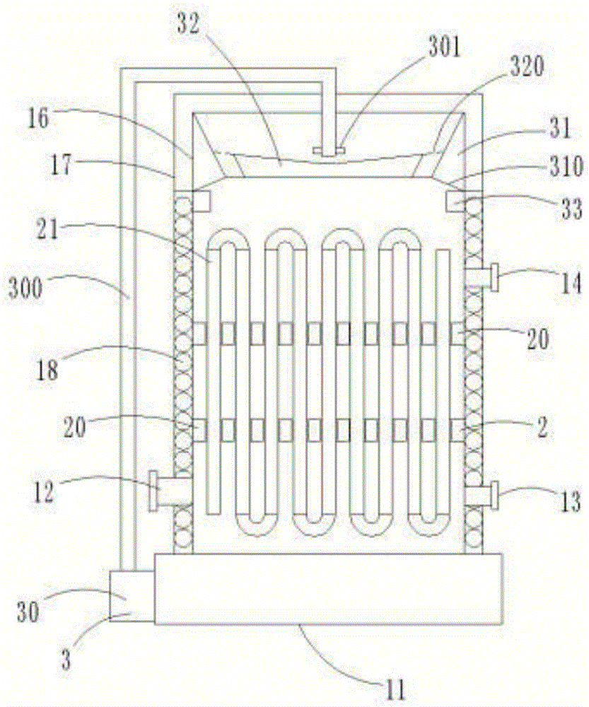
The utility model discloses a waste heat recovery device for high-temperature flue gas in a power plant with smoke elimination function, which comprises a smoke collecting pipe, a heat exchange component and a smoke eliminating component. The smoke collecting pipe is provided with an annular smoke exhaust port, a smoke inlet interface and a heat exchange The liquid inlet, the heat exchange liquid outlet and the liquid discharge port, the heat exchange component includes a buffer plate and a heat exchange tube, the buffer plate is arranged inside the smoke collecting pipe, the buffer plate is provided with an exhaust hole, and the heat exchange tube penetrates and is arranged on the buffer plate , the heat exchange tubes are respectively connected with the heat exchange liquid inlet and the heat exchange liquid outlet; the smoke elimination component includes a blower, an air distribution plate and a cooling plate. The cooling plate is arranged inside the air-distribution plate, an air-distribution groove is formed between the cooling plate and the air-distribution plate, an air supply pipe is arranged on the blower, and the air outlet end of the air supply pipe is directly facing the cooling plate; The waste heat in the high-temperature flue gas of the power plant is thoroughly recycled, which is suitable for mass promotion.
Description
技术领域technical field
本实用新型涉及烟气余热回收技术领域,具体涉及一种具有消烟功能的电厂高温烟气余热回收装置。The utility model relates to the technical field of flue gas waste heat recovery, in particular to a power plant high-temperature flue gas waste heat recovery device with a smoke elimination function.
背景技术Background technique
火电是中国主要的发电方式,火电中又以燃煤电厂为主,燃煤电厂使用煤炭燃烧产生蒸汽驱动发电机组发电,供暖、厂矿企业也有大量燃煤锅炉,煤炭能源具有污染大的特点,煤炭燃烧产生的烟气中含有大量粉尘、含硫含硝污染物等,所以初次燃烧产生的烟气必须经过脱硫脱硝、除尘处理,经过上述处理后的烟气温度在120至180℃之间,这些烟气中携带一定的热量和水蒸气,水蒸气在120℃以上的高温下仍然是气态,这些高温烟气被排入空中以后就可是迅速冷却,烟气中的水蒸气温度降低,凝结成白雾,又称白烟,成为火电厂烟囱上持续排出的景象,烟气中的热量具有极大的利用价值,而且对实现节能减排具有促进作用。Coal-fired power plants are the main power generation method in China. Coal-fired power plants are dominated by coal-fired power plants. Coal-fired power plants use coal combustion to generate steam to drive generator sets to generate electricity. There are also a large number of coal-fired boilers in heating, factories and mining enterprises. The flue gas produced by combustion contains a large amount of dust, sulfur-containing and nitrate-containing pollutants, etc., so the flue gas generated by the initial combustion must undergo desulfurization, denitrification, and dust removal treatment. The flue gas carries a certain amount of heat and water vapor, and the water vapor is still gaseous at high temperatures above 120 °C. After these high-temperature flue gases are discharged into the air, they are rapidly cooled, and the temperature of the water vapor in the flue gas decreases and condenses into white. Fog, also known as white smoke, has become a scene continuously discharged from the chimney of thermal power plants. The heat in the flue gas has great utilization value and promotes energy conservation and emission reduction.
现有的高温烟气余热回收及消烟装置普遍存在以下缺陷:1、设备结构复杂,运行成本高,2、余热回收不够彻底,造成资源的浪费。The existing high-temperature flue gas waste heat recovery and smoke suppression devices generally have the following defects: 1. The equipment structure is complex, and the operating cost is high; 2. The waste heat recovery is not thorough enough, resulting in a waste of resources.
实用新型内容Utility model content
针对上述存在的技术问题,本实用新型提供了一种回收效率高的具有消烟功能的电厂高温烟气余热回收装置。In view of the above existing technical problems, the utility model provides a power plant high-temperature flue gas waste heat recovery device with smoke elimination function with high recovery efficiency.
本实用新型的技术方案为:一种具有消烟功能的电厂高温烟气余热回收装置,包括集烟管、换热组件和消烟组件,集烟管顶端设置有环形排烟口,底部设置有底座,集烟管侧壁上设置有进烟接口、换热液进口、换热液出口和排液口,进烟接口和换热液进口分别位于集烟管下部两侧,换热液进口与外部储液装置连接,换热液出口位于集烟管上部,换热液出口与外部热量利用装置连接;换热组件包括缓冲板和换热管,缓冲板设置有两个,两个缓冲板均设置在集烟管内部,且分别位于集烟管上下两端,两个缓冲板上均设置有排气孔,换热管竖直盘旋设置在集烟管内部,且分别贯穿两个缓冲板,换热管一端与换热液进口连接,另一端与换热液出口连接;消烟组件包括鼓风机、匀气盘和冷却盘,匀气盘为上端开口大、下端开口小的环状结构,匀气盘固定设置在集烟管内部顶端,集烟管内部设置有环形集液槽,环形集液槽位于匀气盘下端,环形集液槽与排液口导通,冷却盘为倒圆台结构,冷却盘通过连杆固定设置在匀气盘内部,冷却盘与匀气盘之间的间隙形成匀气槽,鼓风机与底座固定连接,鼓风机上连接有送风管,送风管的出风端位于集烟管内部,且竖直正对冷却盘中心位置,送风管的出风端水平设置有喷气嘴,鼓风机由外部电源供电。The technical scheme of the utility model is as follows: a power plant high-temperature flue gas waste heat recovery device with smoke elimination function, comprising a smoke collecting pipe, a heat exchange component and a smoke eliminating component. The top of the smoke collecting pipe is provided with an annular smoke exhaust port, and the bottom is provided with a The base, the side wall of the smoke collecting pipe is provided with a smoke inlet interface, a heat exchange liquid inlet, a heat exchange liquid outlet and a liquid discharge port. The external liquid storage device is connected, the heat exchange liquid outlet is located on the upper part of the smoke collecting pipe, and the heat exchange liquid outlet is connected with the external heat utilization device; The heat exchange tube is arranged inside the smoke collecting pipe, and is located at the upper and lower ends of the smoke collecting pipe, respectively. The two buffer plates are provided with exhaust holes. One end of the heat exchange tube is connected to the inlet of the heat exchange liquid, and the other end is connected to the outlet of the heat exchange liquid; the smoke elimination component includes a blower, an air distribution plate and a cooling plate. The gas pan is fixedly arranged at the top of the inside of the smoke collecting pipe. The inside of the flue gas collecting pipe is provided with an annular liquid collecting groove. The annular liquid collecting groove is located at the lower end of the gas uniform plate. The cooling plate is fixedly arranged inside the air-distribution plate through the connecting rod, the gap between the cooling plate and the air-distribution plate forms an air-distribution groove, the blower is fixedly connected with the base, the blower is connected with an air supply pipe, and the air outlet end of the air supply pipe is located at Inside the smoke collecting pipe, and vertically facing the center of the cooling plate, the air outlet end of the air supply pipe is horizontally provided with a jet nozzle, and the blower is powered by an external power supply.
进一步地,集烟管包括内管和外管,内管套设在外管内部,内管和外管之间的空隙盘旋设置有二次热换管,外管的外壁上分别设置有接口一和接口二,接口一和接口二分别与二次热换管的两端导通,通过设置二次热换管,能够对内管内部的热量进行二次回收,提高高温烟气的余热回收效率。Further, the smoke collecting pipe includes an inner pipe and an outer pipe, the inner pipe is sleeved inside the outer pipe, the space between the inner pipe and the outer pipe is spirally arranged with a secondary heat exchange pipe, and the outer wall of the outer pipe is respectively provided with an interface 1 and an interface. The second interface, the first interface and the second interface are respectively connected to both ends of the secondary heat exchange tube. By setting the secondary heat exchange tube, the heat inside the inner tube can be recovered for the second time, and the waste heat recovery efficiency of the high temperature flue gas can be improved.
进一步地,换热管的外壁上周向设置有集热板,通过设置集热板,能够对高温烟气中的热量进行充分吸收,然后将吸收的热量向换热管传递,提高换热效率。Further, the outer wall of the heat exchange tube is provided with a heat collecting plate in the upper circumference. By setting the heat collecting plate, the heat in the high temperature flue gas can be fully absorbed, and then the absorbed heat can be transferred to the heat exchange tube to improve the heat exchange efficiency. .
进一步地,冷却盘顶端设置有凹槽,送风管的出风端竖直正对凹槽的中心位置,通过设置凹槽,使得喷气嘴喷出的气体能够从冷却盘中心向外斜向上吹出,减少喷气嘴喷出的高压气体对冷却盘的冲击。Further, the top of the cooling plate is provided with a groove, and the air outlet end of the air supply pipe is vertically facing the center of the groove. By setting the groove, the gas ejected by the air nozzle can be blown out obliquely upward from the center of the cooling plate. , to reduce the impact of the high-pressure gas ejected by the air nozzle on the cooling plate.
进一步地,匀气盘底部倾斜向外设置有导流台,环形集液槽位于导流台下端,通过设置导流台,当经过换热处理后的高温烟气从冷却盘与匀气盘之间的匀气槽溢出时,被喷气嘴喷出的高压气体迅速冷却,烟气中夹杂的水蒸气冷却后形成水分,从导流台流至环形集液槽中,并最终经过排液口排出。Further, the bottom of the air-distribution pan is provided with a guide table inclined outward, and the annular liquid collecting tank is located at the lower end of the guide table. When the uniform gas tank overflows, the high-pressure gas ejected by the jet nozzle is rapidly cooled, and the water vapor contained in the flue gas is cooled to form moisture, which flows from the guide table to the annular liquid collecting tank, and finally is discharged through the liquid discharge port. .
本实用新型的工作原理为:使用时,将电厂高温烟气通过进烟接口通入内管中,同时将换热液进口与外部清水箱连接,将换热液出口与外部储热水箱连接,电厂高温烟气中的热量被换热管中的清水带走,换热后的烟气通过缓冲板上的排气孔通向集烟管顶端;开启鼓风机,当经过换热处理后的高温烟气从冷却盘与匀气盘之间的匀气槽溢出时,被喷气嘴喷出的高压气体迅速冷却,高温烟气中夹杂的水蒸气冷却后形成水分,从导流台流至环形集液槽中,并最终经过排液口排出;将二次热换管通过接口一和接口二分别与外部清水箱连接,对内管内部的热量进行二次回收。The working principle of the utility model is as follows: when in use, the high-temperature flue gas of the power plant is passed into the inner pipe through the smoke inlet interface, at the same time, the inlet of the heat exchange liquid is connected with the external clean water tank, and the outlet of the heat exchange liquid is connected with the external hot water storage tank, The heat in the high-temperature flue gas of the power plant is taken away by the clean water in the heat exchange pipe, and the flue gas after heat exchange leads to the top of the flue gas collecting pipe through the exhaust hole on the buffer plate; When the gas overflows from the air-distribution groove between the cooling plate and the air-distribution plate, the high-pressure gas ejected by the air nozzle is rapidly cooled, and the water vapor mixed in the high-temperature flue gas is cooled to form moisture, which flows from the guide table to the annular liquid collection The secondary heat exchange tube is connected to the external clean water tank through the first interface and the second interface respectively, and the heat inside the inner tube is recovered for the second time.
与现有技术相比,本实用新型的有益效果是:本实用新型结构设计合理,通过在集烟管内部盘旋设置换热管,并且在集烟管内部设置两个缓冲板,大大降低了高温烟气的上升速率,延长了高温烟气与换热管的换热时间,提高换热效率;通过在集烟管内顶端设置消烟组件,通过鼓风机吹去的气体对高温烟气进行冷却处理,使得高温烟气中夹杂的水蒸气冷却后形成水分,减少了电厂高温烟气冒白烟的现象,减少了视觉污染;通过在内管和外管之间设置二次热换管,对内管内部的热量进行二次回收,大大提高了高温烟气的余热回收效率;通过在冷却盘上设置凹槽,以及设置倾斜的匀气槽,使得喷气嘴喷出的气体不会影响集烟管下部的热量回收。Compared with the prior art, the beneficial effects of the present utility model are: the utility model has a reasonable structure design, and by circling the heat exchange tube inside the smoke collecting pipe, and arranging two buffer plates inside the smoke collecting pipe, the high temperature is greatly reduced. The rising rate of the flue gas prolongs the heat exchange time between the high-temperature flue gas and the heat exchange tube, and improves the heat exchange efficiency. The water vapor contained in the high-temperature flue gas is cooled to form moisture, which reduces the phenomenon of white smoke from the high-temperature flue gas in the power plant and reduces visual pollution; by setting a secondary heat exchange tube between the inner tube and the outer tube, the inner tube The internal heat is recycled for the second time, which greatly improves the waste heat recovery efficiency of high-temperature flue gas; by setting grooves on the cooling plate and setting inclined air-distribution grooves, the gas ejected from the jet nozzle will not affect the lower part of the flue gas collection pipe. heat recovery.
附图说明Description of drawings
图1是本实用新型的内部结构示意图;Fig. 1 is the internal structure schematic diagram of the present utility model;
图2是本实用新型的外部结构示意图;Fig. 2 is the external structure schematic diagram of the present utility model;
图3是本实用新型的集热板在换热管上你的分布图;Fig. 3 is the distribution diagram of the heat collecting plate of the present utility model on the heat exchange tube;
图4是本实用新型的换热管在缓冲板上的分布图;Fig. 4 is the distribution diagram of the heat exchange tube of the present utility model on the buffer plate;
图5是本实用新型的匀气盘和冷却盘的连接示意图;Fig. 5 is the connection schematic diagram of the air distribution plate and the cooling plate of the present invention;
其中,1-集烟管、10-环形排烟口、11-底座、12-进烟接口、13-换热液进口、14-换热液出口、15-排液口、16-内管、17-外管、170-接口一、171-接口二、18-二次热换管、2-换热组件、20-缓冲板、200-排气孔、21-换热管、210-集热板、3-消烟组件、30-鼓风机、300-送风管、301-喷气嘴、31-匀气盘、310-导流台、32-冷却盘、320-匀气槽、321-凹槽、33-环形集液槽。Among them, 1-smoke collecting pipe, 10- annular smoke outlet, 11- base, 12- smoke inlet interface, 13- heat exchange liquid inlet, 14- heat exchange liquid outlet, 15- liquid discharge port, 16- inner pipe, 17-outer pipe, 170-interface one, 171-interface two, 18-secondary heat exchange pipe, 2-heat exchange component, 20-buffer plate, 200-exhaust hole, 21-heat exchange pipe, 210-heat collector Plate, 3-Smoke Elimination Component, 30-Blower, 300-Air Supply Pipe, 301-Air Nozzle, 31-Air Conditioner, 310-Guide Table, 32-Cooling Plate, 320-Air Conditioner, 321-Groove , 33-annular sump.
具体实施方式Detailed ways
实施例:如图1、2所示的一种具有消烟功能的电厂高温烟气余热回收装置,包括集烟管1、换热组件2和消烟组件3,集烟管1顶端设置有环形排烟口10,底部设置有底座11,集烟管1侧壁上设置有进烟接口12、换热液进口13、换热液出口14和排液口15,进烟接口12和换热液进口13分别位于集烟管1下部两侧,换热液进口13与外部储液装置连接,换热液出口14位于集烟管1上部,换热液出口14与外部热量利用装置连接;集烟管1包括内管16和外管17,内管16套设在外管17内部,内管16和外管17之间的空隙盘旋设置有二次热换管18,外管17的外壁上分别设置有接口一170和接口二171,接口一170和接口二171分别与二次热换管18的两端导通,通过设置二次热换管18,能够对内管16内部的热量进行二次回收,提高高温烟气的余热回收效率;Example: As shown in Figures 1 and 2, a power plant high-temperature flue gas waste heat recovery device with smoke eliminating function includes a smoke collecting pipe 1, a
如图1、3、4所示,换热组件2包括缓冲板20和换热管21,缓冲板20设置有两个,两个缓冲板20均设置在集烟管1内部,且分别位于集烟管1上下两端,两个缓冲板20上均设置有排气孔200,换热管21竖直盘旋设置在集烟管1内部,且分别贯穿两个缓冲板20,换热管21一端与换热液进口13连接,另一端与换热液出口14连接;换热管21的外壁上周向设置有集热板210,通过设置集热板210,能够对高温烟气中的热量进行充分吸收,然后将吸收的热量向换热管21传递,提高换热效率;As shown in FIGS. 1 , 3 and 4 , the
如图1、2、5所示,消烟组件3包括鼓风机30、匀气盘31和冷却盘32,匀气盘31为上端开口大、下端开口小的环状结构,匀气盘31固定设置在集烟管1内部顶端,匀气盘31底部倾斜向外设置有导流台310,集烟管1内部设置有环形集液槽33,环形集液槽33位于导流台310下端,通过设置导流台310,当经过换热处理后的高温烟气从冷却盘32与匀气盘31之间的匀气槽320溢出时,被喷气嘴301喷出的高压气体迅速冷却,烟气中夹杂的水蒸气冷却后形成水分,从导流台310流至环形集液槽33中,并最终经过排液口15排出;冷却盘32为倒圆台结构,冷却盘32通过连杆固定设置在匀气盘31内部,冷却盘32与匀气盘31之间的间隙形成匀气槽320,冷却盘32顶端设置有凹槽321,通过设置凹槽321,使得喷气嘴301喷出的气体能够从冷却盘32中心向外斜向上吹出,减少喷气嘴301喷出的高压气体对冷却盘32的冲击;鼓风机30与底座11固定连接,鼓风机30上连接有送风管300,送风管300的出风端竖直正对凹槽321的中心位置,送风管300的出风端水平设置有喷气嘴301;冷却盘32顶端设置有凹槽321,送风管300的出风端竖直正对凹槽321的中心位置,通过设置凹槽321,使得喷气嘴301喷出的气体能够从冷却盘32中心向外斜向上吹出,减少喷气嘴301喷出的高压气体对冷却盘32的冲击,鼓风机30由外部电源供电,鼓风机30选用青岛顺波风机厂生产的4-72型引风机。As shown in Figures 1, 2, and 5, the smoke suppression assembly 3 includes a
使用时,将电厂高温烟气通过进烟接口12通入内管16中,同时将换热液进口13与外部清水箱连接,将换热液出口14与外部储热水箱连接,电厂高温烟气中的热量被换热管21中的清水带走,换热后的烟气通过缓冲板20上的排气孔200通向集烟管1顶端;开启鼓风机30,当经过换热处理后的高温烟气从冷却盘32与匀气盘31之间的匀气槽320溢出时,被喷气嘴301喷出的高压气体迅速冷却,高温烟气中夹杂的水蒸气冷却后形成水分,从导流台310流至环形集液槽33中,并最终经过排液口15排出;将二次热换管18通过接口一170和接口二171分别与外部清水箱连接,对内管16内部的热量进行二次回收。When in use, the high temperature flue gas of the power plant is passed into the
Claims (5)
Priority Applications (1)
| Application Number | Priority Date | Filing Date | Title |
|---|---|---|---|
| CN202020183221.8U CN211782894U (en) | 2020-02-19 | 2020-02-19 | A power plant high temperature flue gas waste heat recovery device with smoke elimination function |
Applications Claiming Priority (1)
| Application Number | Priority Date | Filing Date | Title |
|---|---|---|---|
| CN202020183221.8U CN211782894U (en) | 2020-02-19 | 2020-02-19 | A power plant high temperature flue gas waste heat recovery device with smoke elimination function |
Publications (1)
| Publication Number | Publication Date |
|---|---|
| CN211782894U true CN211782894U (en) | 2020-10-27 |
Family
ID=72908718
Family Applications (1)
| Application Number | Title | Priority Date | Filing Date |
|---|---|---|---|
| CN202020183221.8U Expired - Fee Related CN211782894U (en) | 2020-02-19 | 2020-02-19 | A power plant high temperature flue gas waste heat recovery device with smoke elimination function |
Country Status (1)
| Country | Link |
|---|---|
| CN (1) | CN211782894U (en) |
Cited By (2)
| Publication number | Priority date | Publication date | Assignee | Title |
|---|---|---|---|---|
| CN113532158A (en) * | 2021-07-23 | 2021-10-22 | 泰然机电工程(苏州)有限公司 | Flue gas waste heat recoverer |
| CN115350579A (en) * | 2022-07-28 | 2022-11-18 | 南京中船绿洲环保有限公司 | Sled dress formula msw incineration system rapid cooling deacidification device |
-
2020
- 2020-02-19 CN CN202020183221.8U patent/CN211782894U/en not_active Expired - Fee Related
Cited By (3)
| Publication number | Priority date | Publication date | Assignee | Title |
|---|---|---|---|---|
| CN113532158A (en) * | 2021-07-23 | 2021-10-22 | 泰然机电工程(苏州)有限公司 | Flue gas waste heat recoverer |
| CN113532158B (en) * | 2021-07-23 | 2023-02-21 | 泰然机电工程(苏州)有限公司 | Flue gas waste heat recoverer |
| CN115350579A (en) * | 2022-07-28 | 2022-11-18 | 南京中船绿洲环保有限公司 | Sled dress formula msw incineration system rapid cooling deacidification device |
Similar Documents
| Publication | Publication Date | Title |
|---|---|---|
| CN101245400B (en) | Steelmaking converter gas dry recovery and sensible heat power generation system | |
| CN102243025B (en) | Process and device for recycling flue gas afterheat of electric furnace | |
| CN107398161A (en) | Coal-fired power station boiler flue gas moisture reclaims and the system and method for fine particle removing | |
| CN110864324A (en) | System and method for improving boiler efficiency by using low-temperature waste heat of flue gas | |
| CN105371669B (en) | Flue gas of glass melting furnace and annealing kiln waste gas residual heat combined recovery electricity generation system and method | |
| CN202284894U (en) | Energy-saving environment-friendly cupola furnace | |
| CN205560811U (en) | Boiler flue gas residual heat recycling system | |
| CN108800975A (en) | A kind of flue gas cooling heat exchanger of the desulfurization duct mouth with refrigerating plant | |
| CN110186298A (en) | The recycling of coal steam-electric plant smoke waste heat and eliminating white smoke device | |
| CN202195467U (en) | Coke oven flue gas waste heat recovery system | |
| CN202149473U (en) | Heat-pipe residual-heat boiler system arranged in large flue and small flue of sintering machine | |
| CN211146548U (en) | A system for improving boiler efficiency by utilizing low temperature waste heat of flue gas | |
| CN202151545U (en) | Environment-friendly, energy-saving and efficient multi-stage dust remover | |
| CN210568552U (en) | Boiler energy-saving and flue gas whitening system | |
| CN103614509B (en) | A kind of carbon steel converter dry cloth bag dedusting process of whole process recovery waste heat and device thereof | |
| CN102094686A (en) | Gas, steam and hot air combined circulation device for power generation | |
| CN206145651U (en) | Flue gas waste heat recovery utilizes system | |
| CN206617957U (en) | A kind of phosphorus furnace exhaust gas purification recovery device | |
| CN209679828U (en) | A kind of efficient flue gas takes off white system | |
| CN203625414U (en) | Dry cloth-bag dust removal device for carbon steel converter capable of recovering waste heat in whole process | |
| CN211650305U (en) | High-temperature tail gas purification and waste heat recovery system | |
| CN103528038B (en) | Condensation type float bed energy-saving dust-and-emission-reducing multipurpose boiler | |
| CN111365727B (en) | Flue gas waste heat recovery and purification device of small household biomass boiler | |
| CN201973727U (en) | Regenerative furnace | |
| CN210862296U (en) | Smoke or dead steam dehydration and air cooling system |
Legal Events
| Date | Code | Title | Description |
|---|---|---|---|
| GR01 | Patent grant | ||
| GR01 | Patent grant | ||
| CF01 | Termination of patent right due to non-payment of annual fee |
Granted publication date: 20201027 |
|
| CF01 | Termination of patent right due to non-payment of annual fee |