CN211778205U - Fan frame of radiating fan - Google Patents
Fan frame of radiating fan Download PDFInfo
- Publication number
- CN211778205U CN211778205U CN201922296728.4U CN201922296728U CN211778205U CN 211778205 U CN211778205 U CN 211778205U CN 201922296728 U CN201922296728 U CN 201922296728U CN 211778205 U CN211778205 U CN 211778205U
- Authority
- CN
- China
- Prior art keywords
- motor
- fan
- motor cover
- fan frame
- honeycomb
- Prior art date
- Legal status (The legal status is an assumption and is not a legal conclusion. Google has not performed a legal analysis and makes no representation as to the accuracy of the status listed.)
- Expired - Fee Related
Links
Images


Landscapes
- Structures Of Non-Positive Displacement Pumps (AREA)
Abstract
本实用新型公开了一种散热风扇的扇框,涉及风扇的扇框装置技术领域,为解决现有的散热风扇的扇框为一体结构,在长时间使用的过程中容易导致内部热量不易散失使扇框发生变形的问题。所述外壳的外壁设置有固定板,所述固定板的内部设置有连接孔,所述连接孔的内部设置有固定螺栓,所述连接孔的一侧设置有蜂巢板,所述蜂巢板的内部设置有蜂巢孔,所述固定板的一侧设置有加强台,所述加强台的一侧设置有电机罩,所述电机罩的一侧设置有连接台,所述连接台的内部设置有通孔,所述电机罩的外壁设置有散热槽,所述散热槽的一侧设置有线路孔,所述电机罩的内部设置有卡槽,且卡槽与外壳的下端相适配,所述卡槽的一侧设置有电机板。
The utility model discloses a fan frame of a cooling fan, which relates to the technical field of fan frame devices. In order to solve the problem of the integrated structure of the fan frame of the existing cooling fan, it is easy to cause the internal heat to be difficult to dissipate in the process of long-term use. The problem of deformation of the fan frame. The outer wall of the casing is provided with a fixing plate, the interior of the fixing plate is provided with a connection hole, the interior of the connection hole is provided with a fixing bolt, one side of the connection hole is provided with a honeycomb plate, and the interior of the honeycomb plate is arranged A honeycomb hole is arranged, a reinforcement table is arranged on one side of the fixing plate, a motor cover is arranged on one side of the reinforcement table, a connection table is arranged on one side of the motor cover, and a connection table is arranged inside the connection table. The outer wall of the motor cover is provided with a heat dissipation groove, one side of the heat dissipation groove is provided with a circuit hole, the interior of the motor cover is provided with a card groove, and the card groove is adapted to the lower end of the casing, the card One side of the slot is provided with a motor plate.
Description
技术领域technical field
本实用新型涉及风扇的扇框装置技术领域,具体为一种散热风扇的扇框。The utility model relates to the technical field of fan frame devices of fans, in particular to a fan frame of a cooling fan.
背景技术Background technique
配电柜是电动机控制中心的统称。配电柜使用在负荷比较分散、回路较少的场合;电动机控制中心用于负荷集中、回路较多的场合。配电柜又分低压配电柜和高压配电柜,而高压配电柜是指用于电力系统发电、输电、配电、电能转换和消耗中起通断、控制或保护等作用,主要包括高压断路器、高压隔离开关与接地开关、高压负荷开关、高压自动重合与分段器、高压操作机构、高压防爆配电装置和高压开关柜等几大类,由于配电柜内存在较大的电流以及装置,导致配电柜内部的温度非常高,极易引发电路短路以及火灾现象,人们在对配电柜进行安装的时候往往会放置散热风扇来对热量进行及时的散失,而对于散热风扇来说,它的扇框决定着散热风扇能否长时间工作。Power distribution cabinet is a general term for motor control center. The power distribution cabinet is used in situations where the load is relatively scattered and there are few circuits; the motor control center is used in the situations where the load is concentrated and there are many circuits. Power distribution cabinets are further divided into low-voltage power distribution cabinets and high-voltage power distribution cabinets, while high-voltage power distribution cabinets refer to the functions of on-off, control or protection in power generation, transmission, distribution, power conversion and consumption of power systems, mainly including High-voltage circuit breakers, high-voltage isolating switches and grounding switches, high-voltage load switches, high-voltage automatic reclosing and sectionalizers, high-voltage operating mechanisms, high-voltage explosion-proof power distribution devices and high-voltage switch cabinets, etc. The current and devices cause the temperature inside the power distribution cabinet to be very high, which can easily cause circuit short circuits and fires. When people install the power distribution cabinet, they often place cooling fans to dissipate heat in time. In other words, its fan frame determines whether the cooling fan can work for a long time.
目前现有的散热风扇的扇框为一体结构,在长时间使用的过程中容易导致内部热量不易散失使扇框发生变形的问题;因此,不满足现有的需求,对此我们提出一种散热风扇的扇框。At present, the fan frame of the existing cooling fan has an integrated structure, which is easy to cause the problem that the internal heat is not easily dissipated and the fan frame is deformed during the long-term use. Therefore, it does not meet the existing needs, so we propose a heat dissipation Fan frame.
实用新型内容Utility model content
本实用新型的目的在于提供一种散热风扇的扇框,以解决上述背景技术中提出现有的散热风扇的扇框为一体结构,在长时间使用的过程中容易导致内部热量不易散失而使扇框发生变形的问题。The purpose of the present invention is to provide a fan frame of a cooling fan, in order to solve the problem that the fan frame of the existing cooling fan proposed in the above-mentioned background technology is an integrated structure, and it is easy to cause the internal heat to be difficult to dissipate in the process of long-term use and make the fan The frame is deformed.
为实现上述目的,本实用新型提供如下技术方案:一种散热风扇的扇框,包括外壳,所述外壳的外壁设置有固定板,所述固定板的内部设置有连接孔,所述连接孔的内部设置有固定螺栓,所述连接孔的一侧设置有蜂巢板,所述蜂巢板的内部设置有蜂巢孔,所述固定板的一侧设置有加强台,所述加强台的一侧设置有电机罩,所述电机罩的一侧设置有连接台,所述连接台的内部设置有通孔,所述电机罩的外壁设置有散热槽,所述散热槽的一侧设置有线路孔,所述电机罩的内部设置有卡槽,且卡槽与外壳的下端相适配,所述卡槽的一侧设置有电机板,所述电机板的内部设置有电机固定槽,所述电机板的外壁设置有连接肋,所述电机罩的一侧设置有钢丝盖,所述钢丝盖的外壁设置有固定螺母。In order to achieve the above purpose, the present invention provides the following technical solutions: a fan frame of a cooling fan, including a casing, the outer wall of the casing is provided with a fixing plate, the interior of the fixing plate is provided with a connecting hole, and the connecting hole is A fixing bolt is arranged inside, a honeycomb plate is arranged on one side of the connection hole, a honeycomb hole is arranged inside the honeycomb plate, a reinforcement table is arranged on one side of the fixing plate, and a reinforcement table is arranged on one side of the reinforcement table. Motor cover, one side of the motor cover is provided with a connection table, the interior of the connection table is provided with a through hole, the outer wall of the motor cover is provided with a heat dissipation groove, and one side of the heat dissipation groove is provided with a circuit hole, so The inside of the motor cover is provided with a card slot, and the card slot is adapted to the lower end of the casing, one side of the card slot is provided with a motor plate, the inside of the motor plate is provided with a motor fixing slot, and the motor plate is provided with a motor plate. The outer wall is provided with connecting ribs, one side of the motor cover is provided with a steel wire cover, and the outer wall of the steel wire cover is provided with a fixing nut.
优选的,所述蜂巢孔设置有若干个,且若干个蜂巢孔紧密分布在蜂巢板的内部。Preferably, there are several honeycomb holes, and the several honeycomb holes are closely distributed inside the honeycomb panel.
优选的,所述散热槽设置有若干个,且若干个散热槽分布在电机罩的四周。Preferably, there are several heat dissipation grooves, and the plurality of heat dissipation grooves are distributed around the motor cover.
优选的,所述固定螺栓设置有四个,且四个固定螺栓均匀分布在固定板的四周。Preferably, there are four fixing bolts, and the four fixing bolts are evenly distributed around the fixing plate.
优选的,所述连接台与电机罩为一体结构,且为焊接连接。Preferably, the connection platform and the motor cover are integrally constructed and connected by welding.
优选的,所述连接肋设置有四个,且四个连接肋均匀分布在电机板的四周。Preferably, there are four connecting ribs, and the four connecting ribs are evenly distributed around the motor board.
与现有技术相比,本实用新型的有益效果是:Compared with the prior art, the beneficial effects of the present utility model are:
1、本实用新型通过设置外壳、电机罩和钢丝盖结构,能够提高扇框的强度,从而提高扇框的牢固性,避免在长时间使用中发生断裂,同时能够避免热量过多导致扇框变形。1. The utility model can improve the strength of the fan frame by setting the structure of the casing, the motor cover and the steel wire cover, thereby improving the firmness of the fan frame, avoiding breakage during long-term use, and avoiding the deformation of the fan frame caused by excessive heat. .
2、通过设置有蜂巢孔结构,不仅能够提高热量散失的速度,还能够增大与空气之间的接触面积,从而能够更好的对扇框自身内部的热量进行散失,避免了温度过高发生变形,同时能够避免热量在散失的过程中发生回流现象,提高了散热风扇的散热效率。2. By setting the honeycomb hole structure, it can not only improve the speed of heat dissipation, but also increase the contact area with the air, so as to better dissipate the heat inside the fan frame itself and avoid the occurrence of excessive temperature. At the same time, it can prevent the backflow phenomenon of heat in the process of dissipation, and improve the heat dissipation efficiency of the cooling fan.
3、通过设置连接肋和连接台结构,不仅能够提高电机罩的强度,还能够提高电机罩对温度的承受能力。3. By setting the connecting rib and the connecting table structure, not only the strength of the motor cover can be improved, but also the temperature tolerance of the motor cover can be improved.
附图说明Description of drawings
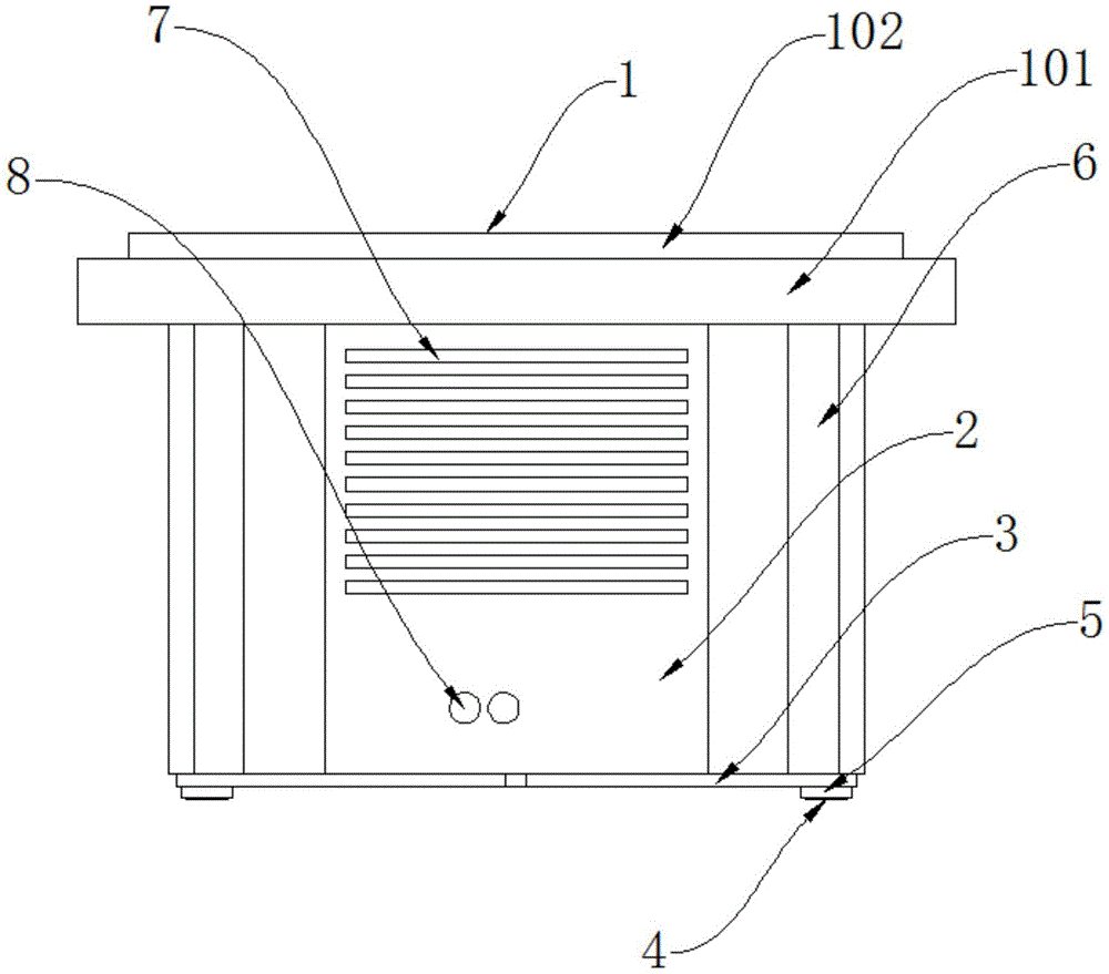
图1为本实用新型的整体主视图;Fig. 1 is the overall front view of the utility model;
图2为本实用新型的整体俯视图;Fig. 2 is the overall plan view of the utility model;
图3为本实用新型的整体仰视图;Fig. 3 is the overall bottom view of the utility model;
图4为本实用新型的电机罩内部结构示意图。4 is a schematic diagram of the internal structure of the motor cover of the present invention.
图中:1、外壳;101、加强台;102、固定板;2、电机罩;201、卡槽;3、钢丝盖;4、固定螺栓;5、固定螺母;6、连接台;601、通孔;7、散热槽;8、线路孔;9、蜂巢板;10、蜂巢孔;11、连接孔;12、电机板;1201、电机固定槽;13、连接肋。In the figure: 1. Shell; 101. Reinforcing table; 102. Fixing plate; 2. Motor cover; 201. Card slot; 3. Steel wire cover; 4. Fixing bolt; 5. Fixing nut; Hole; 7. Heat sink; 8. Line hole; 9. Honeycomb board; 10. Honeycomb hole; 11. Connecting hole; 12. Motor board; 1201. Motor fixing slot;
具体实施方式Detailed ways
下面将结合本实用新型实施例中的附图,对本实用新型实施例中的技术方案进行清楚、完整地描述,显然,所描述的实施例仅仅是本实用新型一部分实施例,而不是全部的实施例。The technical solutions in the embodiments of the present utility model will be clearly and completely described below with reference to the accompanying drawings in the embodiments of the present utility model. Obviously, the described embodiments are only a part of the embodiments of the present utility model, rather than all the implementations. example.
请参阅图1-4,本实用新型提供的一种实施例:一种散热风扇的扇框,包括外壳1,外壳1的外壁设置有固定板102,固定板102的内部设置有连接孔11,能够使外壳1、电机罩2以及钢丝盖3牢牢固定在一起,连接孔11的内部设置有固定螺栓4,连接孔11的一侧设置有蜂巢板9,蜂巢板9的内部设置有蜂巢孔10,能够增大热量的散失,同时增大与空气的接触面积,从而更好的对扇框本身的热量进行散失冷却,固定板102的一侧设置有加强台101,能够提高外壳1的厚度,从而避免温度过高发生变形,加强台101的一侧设置有电机罩2,能够避免电机吸附过多的灰尘,从而减少电路的短路,电机罩2的一侧设置有连接台6,连接台6的内部设置有通孔601,电机罩2的外壁设置有散热槽7,能够及时对电机转动产生的热量进行散失,避免温度过高导致电机烧毁,散热槽7的一侧设置有线路孔8,电机罩2的内部设置有卡槽201,且卡槽201与外壳1的下端相适配,能够提高外壳1与电机罩2之间的牢固性,卡槽201的一侧设置有电机板12,电机板12的内部设置有电机固定槽1201,能够使电机牢牢的固定在里面,电机板12的外壁设置有连接肋13,电机罩2的一侧设置有钢丝盖3,能够进一步提高电机罩2的牢固性,同时避免电机罩2发生变形,钢丝盖3的外壁设置有固定螺母5。1-4, an embodiment provided by the present invention: a fan frame of a cooling fan, comprising a housing 1, the outer wall of the housing 1 is provided with a
进一步,蜂巢孔10设置有若干个,且若干个蜂巢孔10紧密分布在蜂巢板9的内部,能够增大风扇内部的空气流通,从而加快热量的散失,避免温度过高导致扇框变形,同时能够避免热量回流。Further, a plurality of
进一步,散热槽7设置有若干个,且若干个散热槽7分布在电机罩2的四周,能够增大与空气的接触面积,从而及时对扇框本身内部热量的散失,避免扇框由于温度较高发生凹陷或者凸起。Further, there are several
进一步,固定螺栓4设置有四个,且四个固定螺栓4均匀分布在固定板102的四周,能够提高散热风扇的扇框牢固性,从而避免扇框发生变形。Further, four fixing bolts 4 are provided, and the four fixing bolts 4 are evenly distributed around the fixing
进一步,连接台6与电机罩2为一体结构,且为焊接连接,能够提高连接台6的牢固性,同时可以增加电机罩2的厚度,从而能够更好的避免发生变形。Further, the connection table 6 and the
进一步,连接肋13设置有四个,且四个连接肋13均匀分布在电机板12的四周,能够提高电机板12的稳定性,从而避免电机在运行的时候产生较大的振动。Further, four connecting
工作原理:使用时,首先将蜂巢板9放置在外壳1内,使用螺钉进行固定,然后将电机放置在电机罩2的电机固定槽1201内,将风扇叶安装在电机上,并将电机的接线穿过线路孔8裸露在电机罩2的外壁,然后将卡槽201对准外壳1,使外壳1与电机罩2牢牢的固定在一起,接着将钢丝盖3放置在电机板12的外部,将固定螺栓4依次穿过外壳1、电机罩2以及钢丝盖3,再然后使用固定螺母5进行固定,最后将安装好的散热风扇安装在配电柜内,当配电柜内的温度过高时,电机带动的风扇叶转动,通过蜂巢孔10、散热槽7以及钢丝盖3之间的缝隙将热空气与冷空气进行交换,从而完成对配电柜内部的散热过程。Working principle: When using, first place the honeycomb board 9 in the housing 1, fix it with screws, then place the motor in the
对于本领域技术人员而言,显然本实用新型不限于上述示范性实施例的细节,而且在不背离本实用新型的精神或基本特征的情况下,能够以其他的具体形式实现本实用新型。因此,无论从哪一点来看,均应将实施例看作是示范性的,而且是非限制性的,本实用新型的范围由所附权利要求而不是上述说明限定,因此旨在将落在权利要求的等同要件的含义和范围内的所有变化囊括在本实用新型内。不应将权利要求中的任何附图标记视为限制所涉及的权利要求。It will be apparent to those skilled in the art that the present invention is not limited to the details of the above-described exemplary embodiments, and that the present invention may be implemented in other specific forms without departing from the spirit or essential characteristics of the present invention. Therefore, the embodiments are to be considered in all respects as exemplary and not restrictive, and the scope of the present invention is defined by the appended claims rather than the foregoing description, and it is therefore intended that the All changes within the meaning and range of the required equivalents are embraced within the present invention. Any reference signs in the claims shall not be construed as limiting the involved claim.
Claims (6)
Priority Applications (1)
| Application Number | Priority Date | Filing Date | Title |
|---|---|---|---|
| CN201922296728.4U CN211778205U (en) | 2019-12-19 | 2019-12-19 | Fan frame of radiating fan |
Applications Claiming Priority (1)
| Application Number | Priority Date | Filing Date | Title |
|---|---|---|---|
| CN201922296728.4U CN211778205U (en) | 2019-12-19 | 2019-12-19 | Fan frame of radiating fan |
Publications (1)
| Publication Number | Publication Date |
|---|---|
| CN211778205U true CN211778205U (en) | 2020-10-27 |
Family
ID=72975162
Family Applications (1)
| Application Number | Title | Priority Date | Filing Date |
|---|---|---|---|
| CN201922296728.4U Expired - Fee Related CN211778205U (en) | 2019-12-19 | 2019-12-19 | Fan frame of radiating fan |
Country Status (1)
| Country | Link |
|---|---|
| CN (1) | CN211778205U (en) |
-
2019
- 2019-12-19 CN CN201922296728.4U patent/CN211778205U/en not_active Expired - Fee Related
Similar Documents
| Publication | Publication Date | Title |
|---|---|---|
| WO2024098761A1 (en) | Charging device and charging system | |
| CN210273246U (en) | Multifunctional power equipment heat dissipation device | |
| CN221812318U (en) | A kind of industrial frequency UPS uninterruptible power supply | |
| CN201035493Y (en) | Non-noise liquid cooling computer cabinet | |
| CN218070953U (en) | A dense busway with good heat dissipation | |
| CN217389328U (en) | Dustproof heat sink of switch board | |
| CN212910570U (en) | Heat dissipation type wave filter with air-cooled structure | |
| CN210628291U (en) | IGBT module | |
| CN217741107U (en) | Integrated static contact and switch cabinet | |
| CN219458618U (en) | Bus duct with good heat dissipation effect | |
| CN218218139U (en) | Power frequency inverter iron core | |
| CN208188753U (en) | A kind of computer heat emission fan fixed mechanism | |
| CN220457748U (en) | High-heat-dissipation double-drive kart controller | |
| CN211237855U (en) | Resistor box radiator | |
| CN219478396U (en) | High-efficient heat dissipation dc-to-ac converter | |
| CN216052926U (en) | Environment-friendly energy-saving computer case | |
| CN221127803U (en) | Auxiliary heat dissipation structure of circuit board component | |
| CN216959028U (en) | An energy saving and environmental protection electrical equipment cabinet | |
| CN222763437U (en) | A heat dissipation type explosion-proof distribution box | |
| CN221264341U (en) | VPX main control board convenient for heat dissipation | |
| CN211456416U (en) | Electric power cabinet heat sink | |
| CN217134112U (en) | Built-in braking resistor device and inverter including it | |
| CN223246428U (en) | Efficient heat dissipation stator motor | |
| CN221380168U (en) | Inflatable cabinet heat dissipation device and inflatable cabinet | |
| CN219205092U (en) | Panorama back of body string formula silicon controlled rectifier heat abstractor |
Legal Events
| Date | Code | Title | Description |
|---|---|---|---|
| GR01 | Patent grant | ||
| GR01 | Patent grant | ||
| PE01 | Entry into force of the registration of the contract for pledge of patent right |
Denomination of utility model: Fan frame of cooling fan Effective date of registration: 20230113 Granted publication date: 20201027 Pledgee: Bank of China Limited Xiangyang Branch Pledgor: Xiangyang langhong Thermal Technology Co.,Ltd. Registration number: Y2023980031268 |
|
| PE01 | Entry into force of the registration of the contract for pledge of patent right | ||
| CF01 | Termination of patent right due to non-payment of annual fee |
Granted publication date: 20201027 |
|
| CF01 | Termination of patent right due to non-payment of annual fee | ||
| PC01 | Cancellation of the registration of the contract for pledge of patent right |
Granted publication date: 20201027 Pledgee: Bank of China Limited Xiangyang Branch Pledgor: Xiangyang langhong Thermal Technology Co.,Ltd. Registration number: Y2023980031268 |
|
| PC01 | Cancellation of the registration of the contract for pledge of patent right |