CN211775599U - Construction engineering site construction platform - Google Patents
Construction engineering site construction platform Download PDFInfo
- Publication number
- CN211775599U CN211775599U CN202020421773.8U CN202020421773U CN211775599U CN 211775599 U CN211775599 U CN 211775599U CN 202020421773 U CN202020421773 U CN 202020421773U CN 211775599 U CN211775599 U CN 211775599U
- Authority
- CN
- China
- Prior art keywords
- rod
- sliding pair
- sliding
- vertical
- rods
- Prior art date
- Legal status (The legal status is an assumption and is not a legal conclusion. Google has not performed a legal analysis and makes no representation as to the accuracy of the status listed.)
- Withdrawn - After Issue
Links
Images
Landscapes
- Refuge Islands, Traffic Blockers, Or Guard Fence (AREA)
Abstract
本实用新型涉及建筑施工设备,特别是一种建筑工程现场施工平台。包括矩形的底板,底板上部的四角处分别设有竖向的液压缸,液压缸与液压系统管路连接,液压缸的上端安装矩形的承载板;承载板上部的四周安装防护围栏,防护围栏顶端的左纵向防护杆的内侧面设有第一滑动副,第一滑动副的第一滑块与横向的前后移动杆的一端固接;前后移动杆的一侧设有第二滑动副,第二滑动副的第二滑块与竖向的左右移动杆的一端固接;左右移动杆的一侧设有竖向的第三滑动副,第三滑动副的第三滑块与水平设置的上下移动板固接,上下移动板设有用于绑定操作人员的安全绑带;防护围栏为左右对称结构。本实用新型使工人的活动范围得到提高,提高了工人的工作效率。

The utility model relates to building construction equipment, in particular to a construction engineering site construction platform. Including a rectangular base plate, vertical hydraulic cylinders are respectively arranged at the four corners of the upper part of the base plate, the hydraulic cylinder is connected with the hydraulic system pipeline, a rectangular bearing plate is installed on the upper end of the hydraulic cylinder; a protective fence is installed around the upper part of the bearing plate, and the top of the protective fence The inner side of the left longitudinal protection rod is provided with a first sliding pair, and the first sliding block of the first sliding pair is fixedly connected with one end of the horizontal front and rear moving rod; The second sliding block of the sliding pair is fixedly connected with one end of the vertical left and right moving rods; one side of the left and right moving rods is provided with a third vertical sliding pair, and the third sliding block of the third sliding pair is moved up and down with the horizontally arranged The plate is fixed, and the upper and lower moving plates are provided with safety straps for binding operators; the protective fence is a left-right symmetrical structure. The utility model improves the activity range of the workers and improves the work efficiency of the workers.
Description
技术领域technical field
本实用新型涉及建筑施工设备,特别是一种建筑工程现场施工平台。The utility model relates to building construction equipment, in particular to a construction engineering site construction platform.
背景技术Background technique
建筑工程为新建、改建或扩建房屋建筑物和附属构筑物设施所进行的规划、勘察、设计和施工、竣工等各项技术工作和完成的工程实体以及与其配套的线路、管道、设备的安装工程。Construction engineering refers to the planning, survey, design and construction, completion and other technical work and completed engineering entities of new, renovated or expanded buildings and auxiliary structures and facilities, as well as the installation engineering of their supporting lines, pipelines and equipment.
现有的在建筑工程施工的过程中,有些建筑的高度较高,为了方便工人的施工操作,需要用到施工平台来对施工工人进行支撑,在施工时需要对工人进行一定的固定,而固定后大多会导致工人的活动范围受限,影响施工操作。In the existing construction process, some buildings are high in height. In order to facilitate the construction operation of the workers, a construction platform needs to be used to support the construction workers. During the construction, the workers need to be fixed to a certain extent. Most of them will limit the scope of activities of workers and affect construction operations.
实用新型内容Utility model content
本实用新型旨在解决上述技术问题,而提供一种建筑工程现场施工平台,在保证施工人员安全的同时,提高施工人员的活动范围。The utility model aims to solve the above-mentioned technical problems, and provides a construction platform on site of a construction project, which can improve the activity range of the construction personnel while ensuring the safety of the construction personnel.
本实用新型解决其技术问题采用的技术方案是:The technical scheme adopted by the utility model to solve the technical problem is:
一种建筑工程现场施工平台,包括矩形的底板, 底板上部的四角处分别设有竖向的液压缸,液压缸与液压系统管路连接,液压缸的上端安装矩形的承载板;承载板上部的四周安装防护围栏,防护围栏顶端的左纵向防护杆的内侧面设有第一滑动副,第一滑动副的第一滑块与横向的前后移动杆的一端固接;前后移动杆的一侧设有第二滑动副,第二滑动副的第二滑块与竖向的左右移动杆的一端固接;左右移动杆的一侧设有竖向的第三滑动副,第三滑动副的第三滑块与水平设置的上下移动板固接,上下移动板设有用于绑定操作人员的安全绑带;防护围栏为左右对称结构。A construction engineering site construction platform comprises a rectangular base plate, vertical hydraulic cylinders are respectively arranged at four corners of the upper part of the base plate, the hydraulic cylinder is connected with a hydraulic system pipeline, and a rectangular bearing plate is installed on the upper end of the hydraulic cylinder; A protective fence is installed around, the inner side of the left longitudinal protective rod at the top of the protective fence is provided with a first sliding pair, and the first sliding block of the first sliding pair is fixedly connected with one end of the horizontal front and rear moving rod; one side of the front and rear moving rod is provided with a first sliding pair. There is a second sliding pair, the second sliding block of the second sliding pair is fixed with one end of the vertical left and right moving rod; one side of the left and right moving rod is provided with a third vertical sliding pair, and the third sliding pair of the third sliding pair is The sliding block is fixedly connected with the horizontally arranged up and down moving plates, and the up and down moving plates are provided with safety straps for binding operators; the protective fence is a left-right symmetrical structure.
采用上述技术方案的本实用新型与现有技术相比,有益效果是:Compared with the prior art, the utility model adopting the above-mentioned technical scheme has the following beneficial effects:
该建筑工程现场施工平台,通过前后移动杆、左右移动杆和上下移动板的设置,使得在用安全绑带对工人进行固定后,工人的活动范围得到提高,提高了工人的工作效率。The on-site construction platform of the construction project is provided with front and rear moving rods, left and right moving rods and up and down moving plates, so that after the workers are fixed with safety straps, the scope of activities of the workers is improved, and the work efficiency of the workers is improved.
进一步的,本实用新型的优化方案是:Further, the optimization scheme of the present utility model is:
左防护杆的截面为矩形,左防护杆的内侧面设有纵向的第一滑槽结构,第一滑块与第一滑槽结构配合构成第一滑动副;前后移动杆的第二滑动副和上下移动杆的第三滑动副的结构分别与左防护杆的第一滑动副的结构相同。The cross section of the left guard rod is rectangular, and the inner side of the left guard rod is provided with a longitudinal first chute structure, the first sliding block and the first chute structure cooperate to form a first sliding pair; The structure of the third sliding pair of the up-and-down moving rod is respectively the same as that of the first sliding pair of the left protection rod.
防护围栏顶端的前横向防护杆为进出杆组件,前横向防护杆由左至右依次包括卡接杆、活动杆和连接杆,卡接杆的右端面的上部设有半槽结构,活动杆的两端分别设有凸榫结构,卡接杆的半槽结构与活动杆左端凸榫结构通过可拆卸的销轴铰接,连接杆的左端面设有竖向的凹槽结构,活动杆右端的凸榫结构与连接杆左端面的凹槽结构通过销轴铰接。The front lateral protection rod at the top of the protective fence is an entry and exit rod assembly. The front lateral protection rod includes a clamping rod, a movable rod and a connecting rod in sequence from left to right. The upper part of the right end face of the clamping rod is provided with a half-slot structure. The two ends are respectively provided with tenon structures. The half-groove structure of the clamping rod and the tenon structure at the left end of the movable rod are hinged through a detachable pin shaft. The left end face of the connecting rod is provided with a vertical groove structure, and the right end of the movable rod The tenon structure is hinged with the groove structure on the left end face of the connecting rod through a pin shaft.
底板的下表面的四角安装万向轮。Universal wheels are installed at the four corners of the lower surface of the base plate.
底板的左右两端分别设有防滑组件,滑组件包括连接块、丝杆、防滑块和紧固螺母,丝杆的底部固接圆形的防滑块,连接块与丝杆螺纹连接,连接块固接于端面的中部,丝杆旋合紧固螺母。The left and right ends of the bottom plate are respectively provided with anti-skid components. The sliding components include a connecting block, a screw rod, an anti-skid block and a fastening nut. The bottom of the screw rod is fixed with a circular anti-skid block, and the connecting block is threadedly connected with the screw rod. Connected to the middle of the end face, screw the screw to fasten the nut.
前后移动杆的外端的下部设有竖向的支撑杆,支撑杆的下端安装支撑轮。The lower part of the outer end of the front and rear moving rod is provided with a vertical support rod, and the lower end of the support rod is provided with a support wheel.
承载板上表面的中部设有料筒放置槽,后横向防护杆的内侧面安装工具放置箱。The middle part of the upper surface of the carrier plate is provided with a material barrel placement slot, and the inner side of the rear lateral protection rod is provided with a tool placement box.
卡接杆和连接杆内端的下部分别设有竖向的加强杆,加固杆的下端与防护围栏的横向加固杆固接,横向加固杆的两端分别与防护围栏的连接柱固接。The lower parts of the clamping rod and the inner end of the connecting rod are respectively provided with vertical reinforcing rods.
附图说明Description of drawings
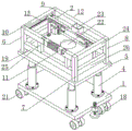
图1为本实用新型实施例的立体示意图;Fig. 1 is the three-dimensional schematic diagram of the embodiment of the present utility model;
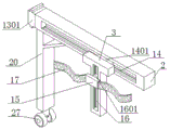
图2为本实用新型实施例的前后移动杆的结构示意图;2 is a schematic structural diagram of a front and rear moving rod according to an embodiment of the present utility model;
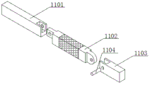
图3为本实用新型实施例的进出杆组的结构示意图;3 is a schematic structural diagram of an in-out rod group according to an embodiment of the present utility model;
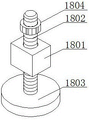
图4为本实用新型实施例的防滑组件的结构示意图;4 is a schematic structural diagram of an anti-skid assembly according to an embodiment of the present invention;
图中:底板1;前后移动杆2;左右移动杆3;液压缸4;承载板5;第一连接柱6;第二连接柱7;第三连接柱8;第四连接柱9;左纵向防护杆10;前横向防护杆11;卡接杆1101;活动杆1102;连接杆1103;销轴1104;后横向防护杆12;第一滑槽结构13;第一滑块1301;第二滑槽结构14;第二滑块1401;上下移动板15;第三滑槽结构16;第三滑块1601;安全绑带17;防滑组件18;连接块1801;丝杆1802;防滑块1803;紧固螺母1804;横向加固杆19;支撑杆20;万向轮21;料筒放置槽22;工具放置箱23;右纵向防护杆24;加强杆25;右纵向加固杆26;支撑轮27。In the figure: bottom plate 1; front and rear moving
具体实施方式Detailed ways
下面结合附图和实施例进一步详述本实用新型。The present utility model will be described in further detail below in conjunction with the accompanying drawings and embodiments.
参见图1,本实施例是一种建筑工程现场施工平台,由底板1、液压缸4、承载板5和防护围栏等构成。长方形的底板1水平设置,底板1底面的四角分别安装万向轮21,万向轮21设有刹车片。底板1的左端面和右端面的中部分别安装有防滑组件18(图4所示),滑组件18由矩形的连接块1801、丝杆1802、防滑块1803和紧固螺母1804构成,丝杆1802的底部焊接圆形的防滑块1803,防滑块1803水平设置,连接块1801与丝杆1802螺纹连接,连接块1801与底板1焊接,丝杆1802上旋合紧固螺母1804。通过防滑组件18的设置,将施工平台移动到合适位置后,按压万向轮21内的刹车片,避免施工平台在使用过程中发生移动,松动丝杆1802至防滑块1803与地面接触,拧紧紧固螺母1804,使得施工平台得到进一步的稳固,避免个别万向轮21的刹车片失灵而导致施工平台使用时发生移动。底板1上表面的四角分别安装液压缸4,液压缸4竖向设置,液压缸4的缸体与底板1通过螺栓连接,液压缸4分别与液压阀台或液压站通过管路连接,液压缸4的活塞杆的顶端安装水平的承载板5,液压缸4用于调整承载板5的高度,承载板5上表面的中部加工有料筒放置槽22,料筒置于料筒放置槽22内,通过料筒放置槽22的设置,在工人施工过程中料筒得到限位,避免发生移动,给工人带来不便。Referring to FIG. 1 , this embodiment is a construction site construction platform of a construction project, which is composed of a base plate 1 , a
承载板5上部的四周安装防护围栏,防护围栏由第一连接柱6、第二连接柱7、第三连接柱8、第四连接柱9、左纵向防护杆10、前横向防护杆11、后横向防护杆12、上下移动板15、安全绑带17、横向加固杆19、右纵向防护杆24、加强杆25和纵向加固杆26等构成。第一连接柱6、第二连接柱7、第三连接柱8和第四连接柱9分别焊接在承载板5上表面的四角,第一连接柱6与第二连接柱7的中部之间、第三连接柱8和第四连接柱9的中部之间焊接横向加固杆19,第一连接柱6和第四连接柱9的的中部之间、第二连接柱7和第三连接柱8的的中部之间焊接纵向加固杆26。第一连接柱6和第二连接柱7的顶端之间焊接前横向防护杆11,第三连接柱8和第四连接柱9的顶端之间焊接后横向防护杆12,第一连接柱6和第四连接柱9的顶端之间焊接左纵向防护杆10,第二连接柱7和第三连接柱8的顶端之间焊接右纵向防护杆24。防护围栏的各个构件的截面均为矩形。A protective fence is installed around the upper part of the
参见图2,防护围栏的左纵向防护杆10的内侧面加工有纵向的第一滑槽结构13,第一滑槽结构13内安装第一滑块1301,第一滑槽结构13和第一滑块1301构成第一滑动副。第一滑块1301与横向设置的前后移动杆2的左端焊接,前后移动杆2左端的下部焊接竖向的支撑杆20,支撑杆20的下端安装支撑轮27,支撑轮27在承载板5上随前后移动杆2前后移动。前后移动杆2的前侧面加工有横向的第二滑槽结构14,第二滑块1401安装在第二滑槽结构14内,第二滑块1401与第二滑槽结构14构成第二滑动副。第二滑块1401与竖向的左右移动杆3的上端焊接,左右移动杆3为T字形;左右移动杆3的前侧面加工有竖向的第三滑槽结构16,第三滑槽结构16内安装第三滑块1601,第三滑槽结构16与第三滑块1601构成第三滑动副。第三滑块1601与横向的上下移动板15焊接,上下移动板15安装固定有安全绑带17,安全绑带17用于绑定操作人员。防护围栏为左右对称结构。本实施例通过前后移动杆2、左右移动杆3和上下移动板15的设置,使得在用安全绑带17对工人进行固定后,工人的活动范围得到提高。Referring to FIG. 2 , a longitudinal
防护围栏顶端的前横向防护杆11为进出杆组件(图3所示),前横向防护杆11由左至右依次由卡接杆1101、活动杆1102和连接杆1103构成,卡接杆101的右端面的上部设有半槽结构,活动杆1102的两端分别设有凸榫结构,卡接杆1101的半槽结构与活动杆1102左端凸榫结构通过可拆卸的销轴铰接,连接杆1103的左端面设有竖向的凹槽结构,活动杆1102右端的凸榫结构与连接杆1103左端面的凹槽结构通过销轴1104铰接。卡接杆1101和连接杆1103内端的下部分别设有竖向的加强杆25,加固杆25的下端与防护围栏的横向加固杆19焊接。施工人员进入承载板5前,打开活动杆1102,进入承载板5后,关闭活动杆1102。后横向防护杆12的内侧面安装工具放置箱23,施工时工人可将工具放置在工具放置箱23内,灵活取放,方便工人操作。The front
以上所述仅为本实用新型较佳可行的实施例而已,并非因此局限本实用新型的权利范围,凡运用本实用新型说明书及附图内容所作的等效结构变化,均包含于本实用新型的权利范围之内。The above descriptions are only preferable and feasible embodiments of the present invention, and are not intended to limit the scope of rights of the present invention. Any equivalent structural changes made by using the contents of the description and accompanying drawings of the present invention are included in the scope of the present invention. within the rights.
Claims (8)
Priority Applications (1)
| Application Number | Priority Date | Filing Date | Title |
|---|---|---|---|
| CN202020421773.8U CN211775599U (en) | 2020-03-28 | 2020-03-28 | Construction engineering site construction platform |
Applications Claiming Priority (1)
| Application Number | Priority Date | Filing Date | Title |
|---|---|---|---|
| CN202020421773.8U CN211775599U (en) | 2020-03-28 | 2020-03-28 | Construction engineering site construction platform |
Publications (1)
| Publication Number | Publication Date |
|---|---|
| CN211775599U true CN211775599U (en) | 2020-10-27 |
Family
ID=72929095
Family Applications (1)
| Application Number | Title | Priority Date | Filing Date |
|---|---|---|---|
| CN202020421773.8U Withdrawn - After Issue CN211775599U (en) | 2020-03-28 | 2020-03-28 | Construction engineering site construction platform |
Country Status (1)
| Country | Link |
|---|---|
| CN (1) | CN211775599U (en) |
Cited By (1)
| Publication number | Priority date | Publication date | Assignee | Title |
|---|---|---|---|---|
| CN111206759A (en) * | 2020-03-28 | 2020-05-29 | 中国二十二冶集团有限公司 | Construction engineering site construction platform |
-
2020
- 2020-03-28 CN CN202020421773.8U patent/CN211775599U/en not_active Withdrawn - After Issue
Cited By (2)
| Publication number | Priority date | Publication date | Assignee | Title |
|---|---|---|---|---|
| CN111206759A (en) * | 2020-03-28 | 2020-05-29 | 中国二十二冶集团有限公司 | Construction engineering site construction platform |
| CN111206759B (en) * | 2020-03-28 | 2024-11-26 | 中国二十二冶集团有限公司 | Construction site platform |
Similar Documents
| Publication | Publication Date | Title |
|---|---|---|
| US9969525B2 (en) | Stand for machine components | |
| CN102071798A (en) | Hydraulic climbing system for wall-attached support frame | |
| CN111206759B (en) | Construction site platform | |
| CN105312798A (en) | Steel structure numerical control assembly center | |
| CN202000658U (en) | Hydraulic climbing system for wall-attached support frame | |
| US3777537A (en) | Vehicle frame and body straightening devices | |
| CN209114320U (en) | A kind of shallow embedding formula bridge extension joint | |
| CN203484579U (en) | Steel bar bending machine | |
| CN213015478U (en) | Steel construction building positioner based on BIM | |
| CN1614195A (en) | Construction method for going through subway station by double circular shielding | |
| CN210549321U (en) | Assembling device for engineering machinery axle | |
| CN209308433U (en) | A multifunctional trolley for binding and installing cast-in-place beam reinforcement cages | |
| CN116160163A (en) | High-precision pneumatic manufacturing platform for crawler beams and manufacturing method thereof | |
| CN218715134U (en) | Connecting buckle for formwork keel | |
| CN212243795U (en) | Welding form flexible unmanned aerial vehicle undercarriage and make its frock locating rack | |
| CN209923701U (en) | Secondary lining trolley guide rail rapid forward movement accurate positioning device | |
| CN222892346U (en) | A protective tool for transporting and storing pipeline modules in nuclear power projects | |
| CN208734345U (en) | A kind of shield tunnel secondary grouting rack | |
| CN203782582U (en) | Device used for mounting bridge crash barrier | |
| CN217668039U (en) | Section bar auxiliary positioning device | |
| CN223073026U (en) | Anti-deformation device for transportation of reinforcement cage | |
| CN219753891U (en) | Steel structure bracket | |
| CN216642653U (en) | Adjustable hydro-cylinder safety support | |
| CN205772901U (en) | A kind of conduction rack | |
| CN202847855U (en) | Chain protective device of crawler track unit |
Legal Events
| Date | Code | Title | Description |
|---|---|---|---|
| GR01 | Patent grant | ||
| GR01 | Patent grant | ||
| AV01 | Patent right actively abandoned |
Granted publication date: 20201027 Effective date of abandoning: 20241126 |
|
| AV01 | Patent right actively abandoned |
Granted publication date: 20201027 Effective date of abandoning: 20241126 |
|
| AV01 | Patent right actively abandoned | ||
| AV01 | Patent right actively abandoned |