CN211770686U - A small integrated sewage treatment equipment - Google Patents
A small integrated sewage treatment equipment Download PDFInfo
- Publication number
- CN211770686U CN211770686U CN201922425441.7U CN201922425441U CN211770686U CN 211770686 U CN211770686 U CN 211770686U CN 201922425441 U CN201922425441 U CN 201922425441U CN 211770686 U CN211770686 U CN 211770686U
- Authority
- CN
- China
- Prior art keywords
- spring
- rod
- sewage treatment
- filter plate
- oil
- Prior art date
- Legal status (The legal status is an assumption and is not a legal conclusion. Google has not performed a legal analysis and makes no representation as to the accuracy of the status listed.)
- Expired - Fee Related
Links
Images


Landscapes
- Sewage (AREA)
Abstract
本实用新型公开了一种小型一体化污水处理设备,包括隔油池和电机,所述隔油池内部安装有过滤装置,所述隔油池的顶端固定连接有收集油液装置,所述隔油池的左侧固定连接有沉淀池,且沉淀池的内部安装有第二滤板,所述隔油池的内部设置有混合装置。本实用新型通过设置有收集油液装置,便于使用者在对污水处理时,将污水中上浮的油层刮出,降低使用者的工作强度,通过设置有过滤装置,便于使用者在刮油同时对第一滤板施加向下的力,不断上下运动,减少第一滤板堵塞现象的产生,设置有混合装置,便于使用者在对污水进行搅拌的同时,将污水中注入混凝剂,使得药剂与污水充分混合,增强污水处理效率。
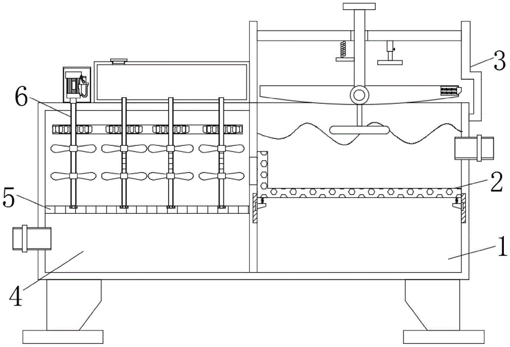
The utility model discloses a small integrated sewage treatment equipment, which comprises an oil separator and a motor. A filter device is installed inside the oil separator, and an oil collecting device is fixedly connected to the top of the oil separator. A sedimentation tank is fixedly connected to the left side of the oil tank, a second filter plate is installed inside the sedimentation tank, and a mixing device is arranged inside the oil separation tank. The utility model is provided with an oil collecting device, which is convenient for the user to scrape out the oil layer floating in the sewage when treating the sewage, thereby reducing the working intensity of the user. The first filter plate exerts a downward force and moves up and down continuously to reduce the occurrence of clogging of the first filter plate. A mixing device is provided to facilitate the user to inject coagulant into the sewage while stirring the sewage, so that the chemical Fully mixed with sewage to enhance sewage treatment efficiency.
Description
技术领域technical field
本实用新型涉及污水处理设备技术领域,具体为一种小型一体化污水处理设备。The utility model relates to the technical field of sewage treatment equipment, in particular to a small integrated sewage treatment equipment.
背景技术Background technique
污水处理是指为使污水达到排入某一水体或再次使用的水质要求对其进行净化的过程,污水处理被广泛应用于建筑、农业、交通、能源、石化、环保、城市景观、医疗、餐饮等各个领域,也越来越多地走进寻常百姓的日常生活,污水在处理过程中常常需要对污水中所含的油渍进行去除,但是现有的一体化污水处理设备常常难以将污水中的油渍进行集中刮取收集,污水处理的效率较低,且现有的一体化污水处理设备中的滤网易产生堵塞的现象,使用寿命较短,现有的一体化污水处理难以在对污水内加入药剂的同时进行搅拌工作,实用性较低,因此亟需一种小型一体化污水处理设备来解决上述问题。Sewage treatment refers to the process of purifying sewage to meet the water quality requirements for discharge into a water body or reuse. Sewage treatment is widely used in construction, agriculture, transportation, energy, petrochemical, environmental protection, urban landscape, medical, catering In various fields, it has also entered the daily life of ordinary people more and more. In the process of sewage treatment, it is often necessary to remove the oil stains contained in the sewage, but the existing integrated sewage treatment equipment is often difficult to remove the oil in the sewage. The oil stains are scraped and collected in a centralized manner, the efficiency of sewage treatment is low, and the filter screen in the existing integrated sewage treatment equipment is prone to clogging, and the service life is short, and the existing integrated sewage treatment is difficult to add to the sewage. Mixing the chemicals at the same time has low practicability, so a small integrated sewage treatment equipment is urgently needed to solve the above problems.
实用新型内容Utility model content
本实用新型的目的在于提供一种小型一体化污水处理设备,以解决上述背景技术中提出的难以将污水中的油渍进行集中刮取收集和滤网易产生堵塞且难以在对污水内加入药剂的同时进行搅拌工作的问题。The purpose of this utility model is to provide a small integrated sewage treatment equipment to solve the problem of difficulty in collecting and scraping the oil stains in the sewage, the filter screen is easy to be blocked, and it is difficult to add chemicals into the sewage. Problems with mixing work.
为实现上述目的,本实用新型提供如下技术方案:一种小型一体化污水处理设备,包括隔油池和电机,所述隔油池内部安装有过滤装置,所述隔油池的顶端固定连接有收集油液装置,所述隔油池的左侧固定连接有沉淀池,且沉淀池的内部安装有第二滤板,所述隔油池的内部设置有混合装置。In order to achieve the above purpose, the utility model provides the following technical scheme: a small integrated sewage treatment equipment, including an oil separator and a motor, a filter device is installed inside the oil separator, and the top of the oil separator is fixedly connected with a A device for collecting oil, a sedimentation tank is fixedly connected to the left side of the oil separation tank, a second filter plate is installed inside the sedimentation tank, and a mixing device is arranged inside the oil separation tank.
优选的,所述过滤装置包括移动块、第一弹簧和第一滤板,所述移动块的顶端通过第一弹簧连接有第一滤板,所述第一滤板设置为L型,且第一滤板的底端连接有第一弹簧的一端,所述第一弹簧的另一端与移动块相连,所述第一滤板通过第一弹簧与移动块构成滑动结构。Preferably, the filter device includes a moving block, a first spring and a first filter plate, the top of the moving block is connected with a first filter plate through a first spring, the first filter plate is L-shaped, and the first filter plate is L-shaped. The bottom end of a filter plate is connected with one end of a first spring, the other end of the first spring is connected with the moving block, and the first filter plate forms a sliding structure with the moving block through the first spring.
优选的,所述收集油液装置包括固定杆、伸缩杆、第二弹簧、按压杆、铰接板、第三弹簧、伸缩块、横杆和竖杆,所述固定杆的上侧底端固定连接有伸缩杆,所述固定杆通过第二弹簧连接有按压杆,所述按压杆的底端连接有铰接板,且铰接板的右侧通过第三弹簧连接有伸缩块,所述铰接板的底端通过横杆连接有竖杆。Preferably, the oil collecting device includes a fixed rod, a telescopic rod, a second spring, a pressing rod, a hinge plate, a third spring, a telescopic block, a horizontal rod and a vertical rod, and the upper bottom end of the fixed rod is fixedly connected There is a telescopic rod, the fixed rod is connected with a pressing rod through a second spring, the bottom end of the pressing rod is connected with a hinge plate, and the right side of the hinge plate is connected with a telescopic block through a third spring, and the bottom of the hinge plate is connected with a telescopic block. The ends are connected with vertical rods through cross rods.
优选的,所述铰接板内部开设有连接槽,且连接槽的连接有第三弹簧的一端,且第三弹簧的另一端与伸缩块相连,所述伸缩块通过第三弹簧与铰接板构成滑动结构。Preferably, a connecting groove is formed inside the hinge plate, and one end of the third spring is connected to the connecting groove, and the other end of the third spring is connected to a telescopic block, and the telescopic block forms a sliding movement with the hinge plate through the third spring structure.
优选的,所述混合装置包括电机、搅拌杆、齿轮、传动带和药剂存放仓,所述电机的输出端连接有搅拌杆,所述电机的右侧固定连接有药剂存放仓。Preferably, the mixing device includes a motor, a stirring rod, a gear, a transmission belt and a medicine storage bin, the output end of the motor is connected with the stirring rod, and the right side of the motor is fixedly connected with the medicine storage bin.
优选的,所述搅拌杆共设置有四组,且四组所述搅拌杆上分别固定套接有齿轮,所述齿轮的外侧与传动带相啮合,其中三组所述搅拌杆设置为空心结构,且搅拌杆上均匀开设有通孔,三组所述搅拌杆的上端均与药剂存放仓相连通。Preferably, a total of four groups of the stirring rods are arranged, and gears are respectively fixed and sleeved on the four groups of the stirring rods, and the outer sides of the gears are meshed with the transmission belt, wherein the three groups of the stirring rods are configured as hollow structures, The stirring rods are evenly provided with through holes, and the upper ends of the three groups of stirring rods are all communicated with the medicament storage bins.
与现有技术相比,本实用新型的有益效果是:该小型一体化污水处理设备设置有收集油液装置,便于将污水中上浮的油层刮出,降低使用者的工作强度,设置有过滤装置,减少第一滤板堵塞现象的产生,设置有混合装置,便于使用者在对污水进行搅拌的同时,将污水中注入混凝剂。Compared with the prior art, the beneficial effects of the present utility model are: the small integrated sewage treatment equipment is provided with an oil collecting device, which is convenient for scraping out the oil layer floating in the sewage, reducing the work intensity of the user, and is provided with a filtering device , to reduce the occurrence of clogging of the first filter plate, and a mixing device is provided, which is convenient for users to inject coagulant into the sewage while stirring the sewage.
(1)该装置通过设置有收集油液装置,便于使用者在对污水处理时,将污水中上浮的油层刮出,降低使用者的工作强度,增强使用者的工作效率。(1) The device is provided with an oil collecting device, which is convenient for the user to scrape out the oil layer floating in the sewage when treating the sewage, thereby reducing the user's work intensity and enhancing the user's work efficiency.
(2)该装置通过设置有过滤装置,便于使用者在刮油同时对第一滤板施加向下的力,不断上下运动,减少第一滤板堵塞现象的产生,增长第一滤板的使用寿命,增强本装置的实用性。(2) The device is provided with a filter device, which is convenient for the user to apply downward force to the first filter plate while scraping oil, and move up and down continuously, reducing the occurrence of clogging of the first filter plate and increasing the use of the first filter plate. life and enhance the practicability of the device.
(3)通过设置有混合装置,便于使用者在对污水进行搅拌的同时,将污水中注入混凝剂,使得药剂与污水充分混合,增强污水处理效率,缩短污水处理时间,进一步增强本装置的实用性。(3) By providing a mixing device, it is convenient for the user to inject coagulant into the sewage while stirring the sewage, so that the agent and the sewage can be fully mixed, the sewage treatment efficiency is enhanced, the sewage treatment time is shortened, and the performance of the device is further enhanced. practicality.
附图说明Description of drawings
图1为本实用新型的结构正视剖面示意图;Fig. 1 is the structural front sectional schematic diagram of the present utility model;
图2为本实用新型的过滤装置结构正视剖面示意图;FIG. 2 is a schematic cross-sectional view of the filter device structure of the present utility model;
图3为本实用新型的收集油液装置结构正视剖面示意图;FIG. 3 is a schematic front cross-sectional view of the structure of the oil collecting device of the present invention;
图4为本实用新型的沉淀池结构正视剖面示意图;Fig. 4 is the front view sectional schematic diagram of the sedimentation tank structure of the present utility model;
图5为本实用新型齿轮和传动带结构俯视示意图。FIG. 5 is a schematic top view of the structure of the gear and transmission belt of the present invention.
图中:1、隔油池;2、过滤装置;21、移动块;22、第一弹簧;23、第一滤板;3、收集油液装置;31、固定杆;32、伸缩杆;33、第二弹簧;34、按压杆;35、铰接板;36、第三弹簧;37、伸缩块;38、横杆;39、竖杆;4、沉淀池;5、第二滤板;6、混合装置;61、电机;62、搅拌杆;63、齿轮;64、传动带;65、药剂存放仓。In the figure: 1, oil trap; 2, filter device; 21, moving block; 22, first spring; 23, first filter plate; 3, oil collecting device; 31, fixed rod; 32, telescopic rod; 33 , the second spring; 34, the pressing rod; 35, the hinge plate; 36, the third spring; 37, the telescopic block; 38, the horizontal rod; 39, the vertical rod; 4, the sedimentation tank; 5, the second filter plate; 6, Mixing device; 61, motor; 62, stirring rod; 63, gear; 64, transmission belt; 65, medicine storage bin.
具体实施方式Detailed ways
下面将结合本实用新型实施例中的附图,对本实用新型实施例中的技术方案进行清楚、完整地描述,显然,所描述的实施例仅仅是本实用新型一部分实施例,而不是全部的实施例。基于本实用新型中的实施例,本领域普通技术人员在没有做出创造性劳动前提下所获得的所有其他实施例,都属于本实用新型保护的范围。The technical solutions in the embodiments of the present utility model will be clearly and completely described below with reference to the accompanying drawings in the embodiments of the present utility model. Obviously, the described embodiments are only a part of the embodiments of the present utility model, rather than all the implementations. example. Based on the embodiments of the present invention, all other embodiments obtained by those of ordinary skill in the art without creative work fall within the protection scope of the present invention.
请参阅图1-5,本实用新型提供的一种实施例:Please refer to Figures 1-5, an embodiment provided by the present utility model:
一种小型一体化污水处理设备,包括隔油池1和电机61,隔油池1内部安装有过滤装置2,过滤装置2包括移动块21、第一弹簧22和第一滤板23,移动块21的顶端通过第一弹簧22连接有第一滤板23,第一滤板23设置为L型,且第一滤板23的底端连接有第一弹簧22的一端,第一弹簧22的另一端与移动块21相连,第一滤板23通过第一弹簧22与移动块21构成滑动结构,当铰接板35向下时,与铰接板35底端通过横杆38相连的竖杆39同步向下,与隔油池1上安装的第一滤板23接触,此时第一滤板23带动与第一滤板23通过第一弹簧22相连的移动块21向下运动,移动块21上安装的滑块在隔油池1内部开设的滑槽中滑动,当竖杆39与第一滤板23不再接触时,第一滤板23通过第一弹簧22的回弹力复位,带动第一滤板23不断上下运动,免于第一滤板23上堆积较多杂质物,产生堵塞的现象,隔油池1的顶端固定连接有收集油液装置3,收集油液装置3包括固定杆31、伸缩杆32、第二弹簧33、按压杆34、铰接板35、第三弹簧36、伸缩块37、横杆38和竖杆39,固定杆31的上侧底端固定连接有伸缩杆32,固定杆31通过第二弹簧33连接有按压杆34,按压杆34的底端连接有铰接板35,且铰接板35的右侧通过第三弹簧36连接有伸缩块37,铰接板35的底端通过横杆38连接有竖杆39,铰接板35内部开设有连接槽,且连接槽的连接有第三弹簧36的一端,且第三弹簧36的另一端与伸缩块37相连,伸缩块37通过第三弹簧36与铰接板35构成滑动结构,使用者可调整伸缩杆32至合适高度,随后向下按压插设在固定杆31上按压杆34,与按压杆34相连的第二弹簧33受力同步向下,带动与按压杆34底端相连的铰接板35一同向下至隔油池1内部,当伸缩块37与隔油池1内壁接触时,隔油池1与伸缩块37接触受力,伸缩块37推动与铰接板35相连的第三弹簧36相靠近第二弹簧33的一侧收缩,此时伸缩块37收缩至第三弹簧36内部开设的连接槽中,此时铰接板35延伸至隔油池1内部对隔油池1上漂浮的油脂进行收集,随后使用者停止按压按压杆34,第二弹簧33带动按压杆34复位,当铰接板35与伸缩杆32接触时,铰接板35的右侧受力向下转动,此时铰接板35呈切斜状态,铰接板35上盛放的油脂沿伸缩块37流至隔油池1外部便于使用者收集,缩短使用者的工作效率,便于使用者将收集的油液流至隔油池1外部进行收集。A small integrated sewage treatment equipment includes an oil separator 1 and a
隔油池1的左侧固定连接有沉淀池4,且沉淀池4的内部安装有第二滤板5,隔油池1的内部设置有混合装置6,混合装置6包括电机61、搅拌杆62、齿轮63、传动带64和药剂存放仓65,电机61的输出端连接有搅拌杆62,电机61的右侧固定连接有药剂存放仓65,搅拌杆62共设置有四组,且四组搅拌杆62上分别固定套接有齿轮63,齿轮63的外侧与传动带64相啮合,其中三组搅拌杆62设置为空心结构,且搅拌杆62上均匀开设有通孔,三组搅拌杆62的上端均与药剂存放仓65相连通,使用者可将混凝剂倒入药剂存放仓65中,此时药剂存放仓65中的药剂流至传动带64内部,当电机61开始工作时,与电机61输出端相连的一组搅拌杆62不断转动,带动固定套接在搅拌杆62上的齿轮63不断转动,与齿轮63相啮合的传动带64随齿轮63一同转动,此时其他三组搅拌杆62通过齿轮63同步转动,搅拌杆62内的混凝剂在转动过程中从通孔中流出至沉淀池4内,同时使得混凝剂与污水充分混合,增强污水处理效率,随后,搅拌完成后的污水沿第二滤板5流至沉淀池4下侧进行再次沉淀工作,沉淀完成后,打开沉淀池4左侧设置的出水口阀门进行收集,进一步增强本装置的实用性。The left side of the oil separation tank 1 is fixedly connected with a
工作原理:当使用需要对污水进行处理时,可打开阀门,将污水从隔油池1上设置的进水口通过隔油池1上安装的过滤装置2注入至隔油池1内部,使得污水进行初次过滤沉淀,沉淀至一定时间后,污水中所含的油脂上浮至隔油池1顶端,此时使用者可调整伸缩杆32至合适高度,随后向下按压插设在固定杆31上按压杆34,与按压杆34相连的第二弹簧33受力同步向下,带动与按压杆34底端相连的铰接板35一同向下至隔油池1内部,当伸缩块37与隔油池1内壁接触时,隔油池1与伸缩块37接触受力,伸缩块37推动与铰接板35相连的第三弹簧36相靠近第二弹簧33的一侧收缩,此时伸缩块37收缩至第三弹簧36内部开设的连接槽中,此时铰接板35延伸至隔油池1内部对隔油池1上漂浮的油脂进行收集,随后使用者停止按压按压杆34,第二弹簧33带动按压杆34复位,当铰接板35与伸缩杆32接触时,铰接板35的右侧受力向下转动,此时铰接板35呈切斜状态,铰接板35上盛放的油脂沿伸缩块37流至隔油池1外部便于使用者收集,缩短使用者的工作效率,同时提高了污水的处理质量,当铰接板35向下时,与铰接板35底端通过横杆38相连的竖杆39同步向下,与隔油池1上安装的第一滤板23接触,此时第一滤板23带动与第一滤板23通过第一弹簧22相连的移动块21向下运动,移动块21上安装的滑块在隔油池1内部开设的滑槽中滑动,当竖杆39与第一滤板23不再接触时,第一滤板23通过第一弹簧22的回弹力复位,带动第一滤板23不断上下运动,免于第一滤板23上堆积较多杂质物,产生堵塞的现象。Working principle: When the sewage needs to be treated, the valve can be opened, and the sewage can be injected into the oil separator 1 from the water inlet set on the oil separator 1 through the
当污水在隔油池1内部初次处理完成后,沿隔油池1上开设的通孔流至沉淀池4上端,此时使用者可将混凝剂倒入药剂存放仓65中,此时药剂存放仓65中的药剂流至传动带64内部,当电机61开始工作时,与电机61输出端相连的一组搅拌杆62不断转动,带动固定套接在搅拌杆62上的齿轮63不断转动,与齿轮63相啮合的传动带64随齿轮63一同转动,此时其他三组搅拌杆62通过齿轮63同步转动,搅拌杆62内的混凝剂在转动过程中从通孔中流出至沉淀池4内,同时使得混凝剂与污水充分混合,增强污水处理效率,随后,搅拌完成后的污水沿第二滤板5流至沉淀池4下侧进行再次沉淀工作,沉淀完成后,打开沉淀池4左侧设置的出水口阀门进行收集。After the initial treatment of sewage in the grease trap 1 is completed, it flows to the upper end of the
对于本领域技术人员而言,显然本实用新型不限于上述示范性实施例的细节,而且在不背离本实用新型的精神或基本特征的情况下,能够以其他的具体形式实现本实用新型。因此,无论从哪一点来看,均应将实施例看作是示范性的,而且是非限制性的,本实用新型的范围由所附权利要求而不是上述说明限定,因此旨在将落在权利要求的等同要件的含义和范围内的所有变化囊括在本实用新型内。不应将权利要求中的任何附图标记视为限制所涉及的权利要求。It will be apparent to those skilled in the art that the present invention is not limited to the details of the above-described exemplary embodiments, and that the present invention may be implemented in other specific forms without departing from the spirit or essential characteristics of the present invention. Therefore, the embodiments are to be considered in all respects as exemplary and not restrictive, and the scope of the present invention is defined by the appended claims rather than the foregoing description, and it is therefore intended that the All changes within the meaning and range of the required equivalents are embraced within the present invention. Any reference signs in the claims shall not be construed as limiting the involved claim.
Claims (6)
Priority Applications (1)
| Application Number | Priority Date | Filing Date | Title |
|---|---|---|---|
| CN201922425441.7U CN211770686U (en) | 2019-12-30 | 2019-12-30 | A small integrated sewage treatment equipment |
Applications Claiming Priority (1)
| Application Number | Priority Date | Filing Date | Title |
|---|---|---|---|
| CN201922425441.7U CN211770686U (en) | 2019-12-30 | 2019-12-30 | A small integrated sewage treatment equipment |
Publications (1)
| Publication Number | Publication Date |
|---|---|
| CN211770686U true CN211770686U (en) | 2020-10-27 |
Family
ID=72977369
Family Applications (1)
| Application Number | Title | Priority Date | Filing Date |
|---|---|---|---|
| CN201922425441.7U Expired - Fee Related CN211770686U (en) | 2019-12-30 | 2019-12-30 | A small integrated sewage treatment equipment |
Country Status (1)
| Country | Link |
|---|---|
| CN (1) | CN211770686U (en) |
-
2019
- 2019-12-30 CN CN201922425441.7U patent/CN211770686U/en not_active Expired - Fee Related
Similar Documents
| Publication | Publication Date | Title |
|---|---|---|
| WO2023130303A1 (en) | Solid and liquid separation device applied to treatment of restaurant wastewater | |
| CN205740434U (en) | Oil-isolating device | |
| CN112110576A (en) | Purifier for sewage treatment | |
| CN108654157A (en) | A kind of movable type prevents the sewage treatment unit of blocking | |
| CN113398639A (en) | Mud water filtration recovery plant is used in municipal administration | |
| CN207445690U (en) | It is a kind of can automatic desilting mud sedimentation basin | |
| CN111467864B (en) | Domestic sewage discharges filtration system | |
| CN110496439B (en) | Prevent sewage treatment plant of jam | |
| CN114632360A (en) | Environment-friendly municipal water supply and drainage sewage treatment device and treatment method | |
| CN111450589A (en) | Sewage treatment is with filtering mechanism who has anti-blocking clearance structure | |
| CN114772696A (en) | Sewage precipitation separation processing apparatus | |
| CN219630704U (en) | Sewage precipitation device | |
| CN221459942U (en) | Energy-saving and environment-friendly wastewater treatment device | |
| CN218248989U (en) | A kind of oil-water separator | |
| CN217323649U (en) | Sewage treatment case that sewage treatment used | |
| CN217418405U (en) | Municipal administration environmental protection sewage sedimentation treatment device | |
| CN214680397U (en) | Oil field water injection scrubbing equipment | |
| CN219333384U (en) | Sewage treatment equipment suitable for urban sewage treatment | |
| CN212799929U (en) | Movable sewage treatment equipment | |
| CN211676509U (en) | Filter equipment for sewage treatment | |
| CN206266275U (en) | A kind of sewage degreasing equipment | |
| CN208694458U (en) | A kind of henhouse flushing chicken manure water purification installation | |
| CN110921871A (en) | Make things convenient for impurity separation's sewage treatment plant | |
| CN223879598U (en) | A wastewater treatment scum removal device | |
| CN210620442U (en) | A filter equipment for sewage treatment |
Legal Events
| Date | Code | Title | Description |
|---|---|---|---|
| GR01 | Patent grant | ||
| GR01 | Patent grant | ||
| PE01 | Entry into force of the registration of the contract for pledge of patent right | ||
| PE01 | Entry into force of the registration of the contract for pledge of patent right |
Denomination of utility model: A small integrated sewage treatment equipment Granted publication date: 20201027 Pledgee: Industrial and Commercial Bank of China Limited Chongqing Yubei Branch Pledgor: Chongqing vertical and horizontal Engineering Design Co.,Ltd. Registration number: Y2024500000044 |
|
| CF01 | Termination of patent right due to non-payment of annual fee | ||
| CF01 | Termination of patent right due to non-payment of annual fee |
Granted publication date: 20201027 |