CN211764084U - A printing arrangement mechanism of a flexographic printing machine - Google Patents
A printing arrangement mechanism of a flexographic printing machine Download PDFInfo
- Publication number
- CN211764084U CN211764084U CN201921702388.4U CN201921702388U CN211764084U CN 211764084 U CN211764084 U CN 211764084U CN 201921702388 U CN201921702388 U CN 201921702388U CN 211764084 U CN211764084 U CN 211764084U
- Authority
- CN
- China
- Prior art keywords
- printing
- rotating shaft
- rollers
- printing machine
- arrangement mechanism
- Prior art date
- Legal status (The legal status is an assumption and is not a legal conclusion. Google has not performed a legal analysis and makes no representation as to the accuracy of the status listed.)
- Expired - Fee Related
Links
Images


Landscapes
- Rotary Presses (AREA)
Abstract
本实用新型公布了一种柔版印刷机的印刷排列机构,包括印刷机,以及设置在印刷机一侧的收集装置;所述印刷机包含了呈凹形的印刷机体,所述印刷机体上设置有多个中心轴,其中两个所述中心轴的外表面设置有印刷版辊,两个所述印刷版辊的两侧相对应位置的中心轴上均分别设置有网纹辊与压印版辊,两个所述网纹辊的一侧相贴近的位置均设置有刮墨刀;其余所述中心轴的外表面均设置有传输转筒,所述传输转筒之间转动连接有印刷材料。本实用新型通过设置两组印刷版辊可以同时在小空间占用率下进行多颜色的印刷工作,同时通过第一转轴与第二转轴的连接关系,通过结构即可自动将印刷完成后的成品材料便捷取出,提高了工作效率。
The utility model discloses a printing arrangement mechanism of a flexographic printing machine, comprising a printing machine and a collecting device arranged on one side of the printing machine; the printing machine comprises a concave printing body, and the printing body is arranged on There are a plurality of central shafts, wherein the outer surfaces of the two central shafts are provided with printing plate rollers, and the central shafts at the corresponding positions on both sides of the two printing plate rollers are respectively provided with an anilox roller and an embossing plate. The two anilox rollers are provided with squeegee blades at the positions close to one side of the two anilox rollers; the outer surfaces of the other central shafts are provided with transmission drums, and printing materials are rotatably connected between the transmission drums. . The utility model can carry out multi-color printing work at the same time with small space occupancy by arranging two sets of printing plate rollers, and at the same time, through the connection relationship between the first rotating shaft and the second rotating shaft, the finished material after the printing can be automatically printed through the structure. Easy to take out and improve work efficiency.
Description
技术领域technical field
本实用新型涉及一种柔版印刷机的印刷排列机构,属于印刷技术领域。The utility model relates to a printing arrangement mechanism of a flexographic printing machine, which belongs to the technical field of printing.
背景技术Background technique
现有的印刷设备在实际柔版印刷包装过程中,为了使产品更有吸引力或更具说明性,常常使用多种颜色的套色叠加来实现,这就需要实际印刷时的印刷设备具有同时印刷多色印刷部套,而多色印刷部套就务必会增加印刷设备的外形长度,这就需要印刷包装厂家提供合适的印刷厂地,但较大的厂房又在无形中增加了印刷包装厂家的包装成本。In the actual flexographic printing and packaging process of the existing printing equipment, in order to make the product more attractive or more explanatory, it is often realized by the superposition of multiple colors, which requires the actual printing equipment to have simultaneous printing. Multi-color printing department sets, and multi-color printing department sets must increase the overall length of the printing equipment, which requires the printing and packaging manufacturers to provide a suitable printing plant, but the larger workshops invisibly increase the printing and packaging manufacturers. packaging costs.
1、由于需要多色的印刷部套单一的设备则需要很多台才可以实现,则占用了大量的设备空间,对厂房的空间有着一定的限制要求,而同时能够使用多色的设备则中心的印刷版辊则尺寸要求大,对于空间高度的占用也是有着一定的限制。1. Since the multi-color printing department requires a single set of equipment, many sets are required to achieve it, which takes up a lot of equipment space and imposes certain restrictions on the space of the workshop. At the same time, multi-color equipment can be used. The printing plate roller has a large size requirement, and there are certain restrictions on the occupation of space height.
2、由于有些收集成品材料的方式多为人工将卷轴拿下在将卷筒卷好的材料拿出来,在安装回原位,这样的操作方式极为麻烦,长期的拆卸操作则容易造成精度问题,导致卷筒卷起来的材料边不够整齐影响美观。2. Because some methods of collecting finished materials are mostly to manually take down the reel, take out the reeled material, and install it back to its original position, such an operation method is extremely troublesome, and long-term disassembly operation is likely to cause accuracy problems. The edge of the material that causes the roll to be rolled up is not neat enough to affect the appearance.
实用新型内容Utility model content
本实用新型目的是针对现有技术存在的缺陷提供一种柔版印刷机的印刷排列机构。The purpose of the utility model is to provide a printing arrangement mechanism of a flexographic printing machine in view of the defects existing in the prior art.
本实用新型为实现上述目的,采用如下技术方案:一种柔版印刷机的印刷排列机构,包括印刷机,以及设置在印刷机一侧的收集装置;In order to achieve the above purpose, the utility model adopts the following technical scheme: a printing arrangement mechanism of a flexographic printing machine, comprising a printing machine and a collecting device arranged on one side of the printing machine;
所述印刷机包含了呈凹形的印刷机体,所述印刷机体上设置有多个中心轴,其中两个所述中心轴的外表面设置有印刷版辊,两个所述印刷版辊的两侧相对应位置的中心轴上均分别设置有网纹辊与压印版辊,两个所述网纹辊的一侧相贴近的位置均设置有刮墨刀;其余所述中心轴的外表面均设置有传输转筒,所述传输转筒之间转动连接有印刷材料,所述印刷机体上设置有两个烘干箱,两个所述烘干箱内均设置有通槽。The printing machine includes a concave printing body, and a plurality of central shafts are arranged on the printing body, wherein the outer surfaces of the two central shafts are provided with printing plate rollers, and two of the two printing plate rollers are arranged on the outer surfaces of the printing plate rollers. An anilox roller and an imprinting plate roller are respectively arranged on the central axis at the corresponding position of the side, and a doctor blade is arranged at the position close to one side of the two anilox rollers; the outer surface of the other central axis Both are provided with transmission drums, and printing materials are rotatably connected between the transmission drums, two drying boxes are arranged on the printing body, and two drying boxes are provided with through grooves.
进一步的,所述收集装置包括放置架;所述放置架的顶部位置设置有第一转轴,所述第一转轴的一端固定连接有连接头,所述连接头的外表面设置有限位块;所述放置架的外表面一侧设置有移动板,所述移动板的顶部与第一转轴相对应的位置设置有第二转轴,所述第二转轴与第一转轴相对应的一端设置有与连接头相嵌套配合的凹槽,所述凹槽内设置有与限位块相嵌套配合的限位槽。Further, the collection device includes a placing rack; a first rotating shaft is arranged at the top of the placing rack, one end of the first rotating shaft is fixedly connected with a connecting head, and a limit block is provided on the outer surface of the connecting head; One side of the outer surface of the placement rack is provided with a moving plate, the top of the moving plate is provided with a second rotating shaft at the position corresponding to the first rotating shaft, and the end of the second rotating shaft corresponding to the first rotating shaft is provided with a connection with the first rotating shaft. The groove is nested and matched with the head, and the groove is provided with a limit groove that is nested and matched with the limit block.
进一步的,所述放置架内与移动板相对应的位置设置有内槽,所述内槽内转动连接有螺杆,所述放置架的外表面设置有驱动端与螺杆固定连接的第二电机,所述螺杆的外表面螺纹套接有螺块,所述螺块的顶部与移动板的底部之间通过连接块固定连接。Further, an inner groove is provided at the position corresponding to the moving plate in the placement rack, a screw rod is rotatably connected in the inner groove, and the outer surface of the placement rack is provided with a second motor whose driving end is fixedly connected with the screw rod, A screw block is threadedly sleeved on the outer surface of the screw rod, and the top of the screw block and the bottom of the moving plate are fixedly connected through a connecting block.
进一步的,所述印刷机体上与两个网纹辊相对应的位置均固定连接有固定块,两个所述固定块内设置有卡槽,两个所述卡槽内均设置有油墨盒,两个所述油墨盒均设置在与两个网纹辊下方对应的位置。Further, the positions corresponding to the two anilox rollers on the printing body are fixedly connected with fixing blocks, the two fixing blocks are provided with card grooves, and the two card grooves are provided with oil ink cartridges, Both of the ink cartridges are arranged at positions corresponding to the underside of the two anilox rollers.
进一步的,所述第一转轴远离连接头的一端嵌套设置有上带轮,所述放置架的一侧设置有第一电机,所述第一电机的驱动端设置有与上带轮相对应的下带轮,所述上带轮与下带轮之间通过皮带转动连接。Further, an upper pulley is nested at one end of the first rotating shaft away from the connector, a first motor is disposed on one side of the placement rack, and a drive end of the first motor is disposed corresponding to the upper pulley. The upper pulley and the lower pulley are connected by belt rotation.
进一步的,所述第二转轴的外表面固定连接有固定卡块,且第二转轴的外表面嵌套有卷筒,所述卷筒的外表面设置有成品材料。Further, the outer surface of the second rotating shaft is fixedly connected with a fixing block, and the outer surface of the second rotating shaft is nested with a reel, and the outer surface of the reel is provided with finished materials.
本实用新型的有益效果:本实用新型整体结构简洁,操作简便,整个结构包含印刷机体以及收集装置,将待印刷的印刷材料通过输送装置输送进入印刷机体内,印刷材料通过中心轴上的传输转筒进入第一个颜色的印刷版辊处,将预先准备好的油墨放置进入对应的油墨盒内,通过网纹辊运输油墨,刮墨刀则会自动将多余的油墨刮下来,通过印刷版辊的转动以及压印版辊的配合工作可以实现自动对印刷材料进行印刷工作,完成后再通过传输转筒输送进入第一个烘干箱中的,通过通槽进行烘干工作,再通过传输转筒输送进入第二个印刷版辊处,通过网纹辊输送油墨盒内的第二个颜色的油墨,配合压印版辊与印刷版辊的转动即可自动实现第二个颜色的印刷工作,再通过传输转筒进入第二个烘干箱中进行烘干,完成后再通过传输转筒输送进入放置架上的卷筒上,启动第一电机,第一电机驱动下带轮转动,下带轮通过皮带带动上带轮转动,上带轮带动第一转轴转动,第一转动通过连接头与凹槽的嵌套连接、限位块与限位槽的嵌套连接即可带动第二转轴转动,第二转轴上的固定卡块则可以带动嵌套再第二转轴上的卷筒转动,可以自动将印刷完成后的成品材料进行卷起来,待卷起工作完成后,启动第二电机,第二电机驱动螺杆转动,螺杆带动螺块移动,螺块则带动移动板移动,移动板上则可以带动第二转轴与第一转轴的连接处打开,同时第二转轴上的固定卡块卡紧的卷筒也会自动带离出来,即可方便取下成品材料,整个结构实现了再低占用空间的同时能够实现多颜色的印刷工作,同时也实现了简化了常规的收集方式,解决了现有的多颜色印刷设备占用空间太大,而单一的印刷虽然空间占用不大但是无法满足多颜色印刷的需求,以及现有的收集方式多为印刷完成后需要人工将卷筒结构拆卸下来再取下成品材料的麻烦步骤的问题。The beneficial effects of the utility model: the overall structure of the utility model is simple and easy to operate. The entire structure includes a printing body and a collecting device. The printing material to be printed is transported into the printing body through the conveying device, and the printing material is transmitted through the central axis. The cylinder enters the printing plate roller of the first color, and the pre-prepared ink is placed into the corresponding ink cartridge, and the ink is transported through the anilox roller. The doctor blade will automatically scrape off the excess ink and pass the printing plate roller. The rotation of the plate and the cooperation of the platen roller can realize the automatic printing of the printing materials, and after the completion, the materials are transported into the first drying box through the transmission drum, and the drying work is carried out through the through groove, and then passed through the transmission drum. The cylinder is transported into the second printing plate roller, and the ink of the second color in the ink cartridge is transported through the anilox roller, and the printing of the second color can be automatically realized with the rotation of the embossing plate roller and the printing plate roller. Then enter the second drying box through the transmission drum for drying, and then transport it into the drum on the placing rack through the transmission drum, start the first motor, the first motor drives the lower pulley to rotate, and the lower belt rotates. The pulley drives the upper pulley to rotate through the belt, and the upper pulley drives the first rotating shaft to rotate. , the fixed block on the second rotating shaft can drive the reel nested on the second rotating shaft to rotate, and the finished material after printing can be rolled up automatically. The second motor drives the screw to rotate, the screw drives the screw block to move, the screw block drives the moving plate to move, and the moving plate can drive the connection between the second shaft and the first shaft to open, and the fixed block on the second The reel will also be automatically taken out, and the finished material can be easily removed. The whole structure realizes the multi-color printing work while reducing the occupied space. It also simplifies the conventional collection method and solves the problem of existing The multi-color printing equipment takes up too much space, and although a single printing does not take up much space, it cannot meet the needs of multi-color printing, and most of the existing collection methods require manual disassembly and removal of the roll structure after the printing is completed. The problem with the troublesome steps of the finished material.
附图说明Description of drawings
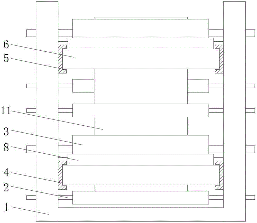
图1为本实用新型的正视图;Fig. 1 is the front view of the utility model;
图2为本实用新型的侧视图;Fig. 2 is the side view of the utility model;
图3为本实用新型的收集装置正视图;Fig. 3 is the front view of the collecting device of the utility model;
图4为本实用新型的图3中A处的放大图。FIG. 4 is an enlarged view of the position A in FIG. 3 of the present invention.
具体实施方式Detailed ways
图1至图4所示,涉及一种柔版印刷机的印刷排列机构,包括印刷机,以及设置在印刷机一侧的收集装置;所述印刷机包含了呈凹形的印刷机体1,所述印刷机体1上设置有多个中心轴2,其中两个所述中心轴2的外表面设置有印刷版辊3,两个所述印刷版辊 3的两侧相对应位置的中心轴2上均分别设置有网纹辊7与压印版辊9,两个所述网纹辊 7的一侧相贴近的位置均设置有刮墨刀8;其余所述中心轴2的外表面均设置有传输转筒 10,所述传输转筒10之间转动连接有印刷材料11,所述印刷机体1上设置有两个烘干箱 12,两个所述烘干箱12内均设置有通槽13;所述收集装置包括放置架14;所述放置架 14的顶部位置设置有第一转轴15,所述第一转轴15的一端固定连接有连接头20,所述连接头20的外表面设置有限位块21;所述放置架14的外表面一侧设置有移动板27,所述移动板27的顶部与第一转轴15相对应的位置设置有第二转轴22,所述第二转轴22 与第一转轴15相对应的一端设置有与连接头20相嵌套配合的凹槽23,所述凹槽23内设置有与限位块21相嵌套配合的限位槽24。As shown in Fig. 1 to Fig. 4, it relates to a printing arrangement mechanism of a flexographic printing machine, including a printing machine and a collecting device arranged on one side of the printing machine; the printing machine includes a
使用时,将待印刷的印刷材料通过输送装置输送进入印刷机体1内,印刷材料通过中心轴上的传输转筒10进入第一个颜色的印刷版辊3处,将预先准备好的油墨放置进入对应的油墨盒6内,通过网纹辊7运输油墨,刮墨刀8则会自动将多余的油墨刮下来,通过印刷版辊3的转动以及压印版辊9的配合工作可以实现自动对印刷材料进行印刷工作,完成后再通过传输转筒10输送进入第一个烘干箱12中的,通过通槽13进行烘干工作,再通过传输转筒10输送进入第二个印刷版辊3处,通过网纹辊7输送油墨盒6内的第二个颜色的油墨,配合压印版辊3与印刷版辊3的转动即可自动实现第二个颜色的印刷工作,再通过传输转筒10进入第二个烘干箱12中进行烘干,完成后再通过传输转筒 10输送进入放置架14上的卷筒26上,启动第一电机19,第一电机19驱动下带轮17转动,下带轮17通过皮带18带动上带轮16转动,上带轮16带动第一转轴15转动,第一转轴15通过连接头20与凹槽23的嵌套连接、限位块21与限位槽24的嵌套连接即可带动第二转轴22转动,第二转轴22上的固定卡块25则可以带动嵌套再第二转轴22上的卷筒26转动,可以自动将印刷完成后的成品材料进行卷起来,待卷起工作完成后,启动第二电机30,第二电机30驱动螺杆29转动,螺杆29带动螺块31移动,螺块31则带动移动板27移动,移动板27上则可以带动第二转轴22与第一转轴15的连接处打开,同时第二转轴22上的固定卡块25卡紧的卷筒26也会自动带离出来,即可方便取下成品材料。When in use, the printing material to be printed is transported into the
进一步的方案中,所述放置架14内与移动板27相对应的位置设置有内槽28,所述内槽28内转动连接有螺杆29,所述放置架14的外表面设置有驱动端与螺杆29固定连接的第二电机30,所述螺杆29的外表面螺纹套接有螺块31,所述螺块31的顶部与移动板 27的底部之间通过连接块32固定连接,通过第二电机30驱动螺杆29转动即可自动带动螺块31移动,螺块31通过连接块32即可带动移动板27移动,通过传动结构即可自动实现第一转轴15与第二转轴22分离,从而可以方便收集成品材料33。In a further solution, an
进一步的方案中,所述印刷机体1上与两个网纹辊7相对应的位置均固定连接有固定块4,两个所述固定块4内设置有卡槽5,两个所述卡槽5内均设置有油墨盒6,两个所述油墨盒6均设置在与两个网纹辊7下方对应的位置,通过固定块4上的卡槽5即方便放置油墨盒6,同时也方便收取进行清理工作。In a further solution, the positions corresponding to the two
进一步的方案中,所述第一转轴15远离连接头20的一端嵌套设置有上带轮16,所述放置架14的一侧设置有第一电机19,所述第一电机19的驱动端设置有与上带轮16 相对应的下带轮17,所述上带轮16与下带轮17之间通过皮带18转动连接,通过第一电机19驱动下带轮17转动,通过皮带18即可带动上带轮16转动,上带轮16则会自动带动第一转轴15转动,通过结构即可自动实现收集工作。In a further solution, an
其中,所述第二转轴22的外表面固定连接有固定卡块25,且第二转轴22的外表面嵌套有卷筒26,所述卷筒26的外表面设置有成品材料33,固定卡块25可以将卷筒26 固定卡在在第二转轴22上,方便印刷收集完成后能够将成品材料33取下。Wherein, the outer surface of the second rotating
以上所述仅为本实用新型的较佳实施例,并不用以限制本实用新型,凡在本实用新型的精神和原则之内,所作的任何修改、等同替换、改进等,均应包含在本实用新型的保护范围之内。The above are only preferred embodiments of the present invention, and are not intended to limit the present invention. Any modifications, equivalent replacements, improvements, etc. made within the spirit and principles of the present invention shall be included in the present invention. within the scope of protection of the utility model.
Claims (6)
Priority Applications (1)
| Application Number | Priority Date | Filing Date | Title |
|---|---|---|---|
| CN201921702388.4U CN211764084U (en) | 2019-10-12 | 2019-10-12 | A printing arrangement mechanism of a flexographic printing machine |
Applications Claiming Priority (1)
| Application Number | Priority Date | Filing Date | Title |
|---|---|---|---|
| CN201921702388.4U CN211764084U (en) | 2019-10-12 | 2019-10-12 | A printing arrangement mechanism of a flexographic printing machine |
Publications (1)
| Publication Number | Publication Date |
|---|---|
| CN211764084U true CN211764084U (en) | 2020-10-27 |
Family
ID=72934981
Family Applications (1)
| Application Number | Title | Priority Date | Filing Date |
|---|---|---|---|
| CN201921702388.4U Expired - Fee Related CN211764084U (en) | 2019-10-12 | 2019-10-12 | A printing arrangement mechanism of a flexographic printing machine |
Country Status (1)
| Country | Link |
|---|---|
| CN (1) | CN211764084U (en) |
-
2019
- 2019-10-12 CN CN201921702388.4U patent/CN211764084U/en not_active Expired - Fee Related
Similar Documents
| Publication | Publication Date | Title |
|---|---|---|
| CN107599624A (en) | A kind of printing equipment with drying function | |
| CN214267034U (en) | A kind of anti-counterfeiting label printing equipment | |
| CN207359854U (en) | Gloves automatic turnover printing machine | |
| CN219523316U (en) | A flexographic printing machine | |
| CN108675026A (en) | Feeding hot stamping mechanism for stamping machine | |
| CN113211954B (en) | Double-sided printing machine | |
| CN207565143U (en) | A kind of printing equipment with drying function | |
| CN210759702U (en) | Flexographic printing machine | |
| CN216359850U (en) | Printing machine | |
| CN106696452B (en) | Die cutting and coloring integrated equipment and processing method for die cutting and coloring paper | |
| CN111716876A (en) | Printing mechanism of flexible plate printing machine | |
| CN214984091U (en) | Corrugated paper rotary ink printing device | |
| CN214449338U (en) | All-in-one screen printing machine for label printing | |
| CN210234331U (en) | An oversized printing machine | |
| CN216183579U (en) | Single-layer type soft plate printing machine | |
| CN211280171U (en) | Multicolor quick pad printing dryer for marking pen shell | |
| CN219969177U (en) | A carton printing surface cleaning mechanism | |
| CN218986068U (en) | Novel corrugated case printing device | |
| CN219096293U (en) | Stop gear is used in inspection of heat-transfer seal reverse mould | |
| CN218702021U (en) | Flexographic printing machine is used in plastic woven sack production | |
| CN223821277U (en) | Printing device for aluminum foil packaging film | |
| CN213445497U (en) | Continuous folding mechanism for printing folding machine | |
| CN219133584U (en) | Water-soluble laminating machine | |
| CN220641812U (en) | Cardboard leading-in device for carton printing machine | |
| CN216783102U (en) | Even calico printing machine of abundant stamp of cloth laminating |
Legal Events
| Date | Code | Title | Description |
|---|---|---|---|
| GR01 | Patent grant | ||
| GR01 | Patent grant | ||
| CF01 | Termination of patent right due to non-payment of annual fee | ||
| CF01 | Termination of patent right due to non-payment of annual fee |
Granted publication date: 20201027 |