CN211760592U - Injection molding burr remove device - Google Patents
Injection molding burr remove device Download PDFInfo
- Publication number
- CN211760592U CN211760592U CN201922389126.3U CN201922389126U CN211760592U CN 211760592 U CN211760592 U CN 211760592U CN 201922389126 U CN201922389126 U CN 201922389126U CN 211760592 U CN211760592 U CN 211760592U
- Authority
- CN
- China
- Prior art keywords
- fixedly connected
- clamp
- injection molding
- side plates
- tool
- Prior art date
- Legal status (The legal status is an assumption and is not a legal conclusion. Google has not performed a legal analysis and makes no representation as to the accuracy of the status listed.)
- Expired - Fee Related
Links
Images


Landscapes
- Processing And Handling Of Plastics And Other Materials For Molding In General (AREA)
Abstract
本实用新型公开了一种注塑件毛刺去除装置,包括包括一个底座,所述底座两侧上端固定连接有对称设置的侧板,两个所述侧板相对一侧底部均开设有第一滑槽,两个实用新型的有益效果是:本实用新型一种注塑件毛刺去除装置,通过设置液压机、移动杆、滑块、刀具、夹具、从动齿轮、主动齿轮和驱动电机来实现快速去毛刺,通过驱动电机带动转轴高速转动,刀具去除毛刺,后期可以灵活换刀具进行抛光打磨,本装置加工速度快,可灵活根据加工物体来调节夹具的大小,也可以对加工物体毛刺加工情况来跟换其他刀具来进行精加工,而在加工过程中,侧壁可以阻挡飞溅的残渣、毛刺保护工作人员,底部安装移动轮,方便移动。
The utility model discloses a burr removal device for injection molded parts, which comprises a base, the upper ends of the two sides of the base are fixedly connected with symmetrically arranged side plates, and the bottoms of the opposite sides of the two side plates are both provided with a first chute The beneficial effects of the two utility models are: the utility model is a burr removal device for injection molded parts, which realizes rapid deburring by setting a hydraulic press, a moving rod, a slider, a tool, a fixture, a driven gear, a driving gear and a drive motor, By driving the motor to drive the shaft to rotate at a high speed, the tool can remove burrs, and the tool can be flexibly changed for polishing and grinding later. The tool is used for finishing, and during the processing, the side wall can block the splashing residue and burrs to protect the staff, and the bottom is equipped with a moving wheel for easy movement.
Description
技术领域technical field
本实用新型涉及一种毛刺去除装置,特别涉及一种注塑件毛刺去除装置,属于注塑件加工技术领域。The utility model relates to a burr removal device, in particular to a burr removal device for injection molded parts, which belongs to the technical field of injection molded parts processing.
背景技术Background technique
机械零件上的毛刺,有些是由于切削加工过程中塑性变形引起的;有些是铸造、模锻等加工的飞边,还有些是焊接挤出的残料。随着工业化和自动化程度的提高,机械加工领域,特别是航空、航天、仪器仪表领域中,对机械零件制造精度要求的提高和机构设计的微型化,毛刺的危害性尤为明显,逐渐引起人们的普遍重视,并开始对毛刺的生成机理及去除方法进行研究。Some burrs on mechanical parts are caused by plastic deformation during the cutting process; some are burrs from casting, die forging, etc., and some are residual materials from welding and extrusion. With the improvement of industrialization and automation, in the field of mechanical processing, especially in the fields of aviation, aerospace, and instrumentation, the requirements for the manufacturing accuracy of mechanical parts and the miniaturization of mechanism design are increasing. General attention, and began to study the burr generation mechanism and removal methods.
现在在对注塑件去毛刺时,夹具往往只能对同一规格物体进行夹持,遇到不同型号加工件时需要更换夹具头,且某些机器无法灵活跟换去除毛刺的刀具,且毛刺夹具夹持单一性,不能灵活变换。Now when deburring injection molded parts, the clamps can only clamp objects of the same specification. When encountering different types of workpieces, the clamp head needs to be replaced, and some machines cannot flexibly change the deburring tool, and the burr clamp clamps It is single and cannot be changed flexibly.
实用新型内容Utility model content
本实用新型要解决的技术问题是克服现有技术的缺陷,提供一种注塑件毛刺去除装置,以解决上述背景技术中提到的问题。The technical problem to be solved by the present invention is to overcome the defects of the prior art and provide a burr removal device for injection molded parts, so as to solve the problems mentioned in the above background art.
为了解决上述技术问题,本实用新型提供了如下的技术方案:本实用新型一种注塑件毛刺去除装置,包括一个底座,所述底座上表面固定连接有两块呈对称设置的侧板,两块所述侧板靠近顶端的相向位置上均开设有第一滑槽,两个所述侧板的上端共同固定连接有一根横杆,所述横杆中部固定安装有伸缩气缸,所述伸缩气缸的输出端活动连接有活塞杆,所述活塞杆下端固定连接有移动杆,所述移动杆下端固定连接有一夹具,所述第一夹具内侧壁开设有具槽,所述刀具槽内侧壁活动连接有刀具,所述刀具相对外侧壁上开设有凹槽,所述第一夹具上活动连接有两根活动插销,所述活动插销穿过第一夹具内部且延伸插设于凹槽内部,两块所述侧板靠近底端位置的相向侧壁之间共同固定连接有一块固定板,所述固定板中部固定安装有轴承,所述固定板中心处通过轴承转动连接有转轴,所述转轴上端固定连接固定圆台,所述固定圆台上表面呈对称设置开设有两个椭圆弧形的第二滑槽,两个所述第二滑槽内均滑动连接有一块第二滑块,两块第二滑块的上端均延伸至第二滑槽外且固定连接有一个第二夹具,所述转轴下端固定连接从动齿轮,所述底座的上表面固定连接有一个驱动电机,所述驱动电机的输出端通过联轴器固定连接有一个主动齿轮,所述主动齿轮与从动齿轮相啮合。In order to solve the above technical problems, the present utility model provides the following technical solutions: the utility model is a burr removal device for injection molded parts, comprising a base, and two symmetrically arranged side plates are fixedly connected to the upper surface of the base, and two A first chute is provided at the opposite positions of the side plates near the top, and a cross bar is fixedly connected to the upper ends of the two side plates. A telescopic cylinder is fixedly installed in the middle of the cross bar. The output end is movably connected with a piston rod, the lower end of the piston rod is fixedly connected with a moving rod, the lower end of the moving rod is fixedly connected with a clamp, the inner side wall of the first clamp is provided with a groove, and the inner side wall of the tool groove is movably connected with a The cutter is provided with a groove on the opposite outer side wall, and two movable pins are movably connected to the first clamp. The movable pins pass through the interior of the first clamp and are extended and inserted into the groove. A fixed plate is fixedly connected between the opposite side walls near the bottom end of the side plate, a bearing is fixedly installed in the middle of the fixed plate, a rotating shaft is rotatably connected to the center of the fixed plate through the bearing, and the upper end of the rotating shaft is fixedly connected A fixed round table, the upper surface of the fixed round table is symmetrically arranged with two second elliptical arc-shaped second chute, two second sliding grooves are slidably connected with a second sliding block, two second sliding blocks The upper end of the shaft extends to the outside of the second chute and is fixedly connected with a second clamp, the lower end of the rotating shaft is fixedly connected to the driven gear, the upper surface of the base is fixedly connected with a drive motor, and the output end of the drive motor passes through The coupling is fixedly connected with a driving gear, and the driving gear meshes with the driven gear.
作为本实用新型的一种优选技术方案,所述移动杆两侧均连接第一滑块,两块所述第一滑块远离移动杆的一端分别延伸至两个第一滑槽内。As a preferred technical solution of the present invention, both sides of the moving rod are connected with first sliding blocks, and one end of the two first sliding blocks away from the moving rod extends into the two first sliding grooves respectively.
作为本实用新型的一种优选技术方案,两个所述侧板下端均固定连接有两个轮座,四个所述轮座下端均固定连接自锁万向轮。As a preferred technical solution of the present invention, the lower ends of the two side plates are fixedly connected with two wheel bases, and the lower ends of the four wheel bases are fixedly connected with self-locking universal wheels.
作为本实用新型的一种优选技术方案,两个所述第二夹具外侧壁固定连接螺母件,所述螺母件内部共同螺纹连接有一根螺栓,两个所述第二夹具远离螺母件的一端均固定连接有连接件,两个所述连接件之间通过合页转动连接。As a preferred technical solution of the present invention, the outer side walls of the two second clamps are fixed and connected to a nut piece, a bolt is threadedly connected to the inside of the nut piece, and one end of the two second clamps away from the nut piece is A connecting piece is fixedly connected, and the two connecting pieces are rotatably connected through a hinge.
作为本实用新型的一种优选技术方案,所述第二夹具均呈半椭圆形装设置。As a preferred technical solution of the present invention, the second clamps are all arranged in a semi-elliptical shape.
作为本实用新型的一种优选技术方案,所述底座的上表面固定安装有支架,所述支架的顶端固定连接在驱动电机的外侧壁上。As a preferred technical solution of the present invention, a bracket is fixedly installed on the upper surface of the base, and the top end of the bracket is fixedly connected to the outer side wall of the driving motor.
本实用新型的有益效果是:本实用新型一种注塑件毛刺去除装置,通过设置液压机、移动杆、滑块、刀具、夹具、从动齿轮、主动齿轮和驱动电机来实现快速去毛刺,通过驱动电机带动转轴高速转动,刀具去除毛刺,后期可以灵活换刀具进行抛光打磨,本装置加工速度快,可灵活根据加工物体来调节夹具的大小,也可以对加工物体毛刺加工情况来跟换其他刀具来进行精加工,而在加工过程中,侧壁可以阻挡飞溅的残渣、毛刺保护工作人员,底部安装移动轮,方便移动。The beneficial effects of the utility model are as follows: the utility model is a burr removal device for injection molded parts, which realizes rapid deburring by setting a hydraulic press, a moving rod, a slider, a cutter, a clamp, a driven gear, a driving gear and a driving motor, and is driven by The motor drives the shaft to rotate at a high speed, the tool removes burrs, and the tool can be flexibly changed for polishing and grinding later. This device has a fast processing speed, and can flexibly adjust the size of the fixture according to the processed object, and can also change other tools for the burr processing of the processed object. Finishing is carried out, and during the processing, the side wall can block the splashing residue and burrs to protect the staff, and the bottom is equipped with a moving wheel for easy movement.
附图说明Description of drawings
附图用来提供对本实用新型的进一步理解,并且构成说明书的一部分,与本实用新型的实施例一起用于解释本实用新型,并不构成对本实用新型的限制。在附图中:The accompanying drawings are used to provide a further understanding of the present invention, and constitute a part of the specification, and are used to explain the present invention together with the embodiments of the present invention, and do not constitute a limitation to the present invention. In the attached image:
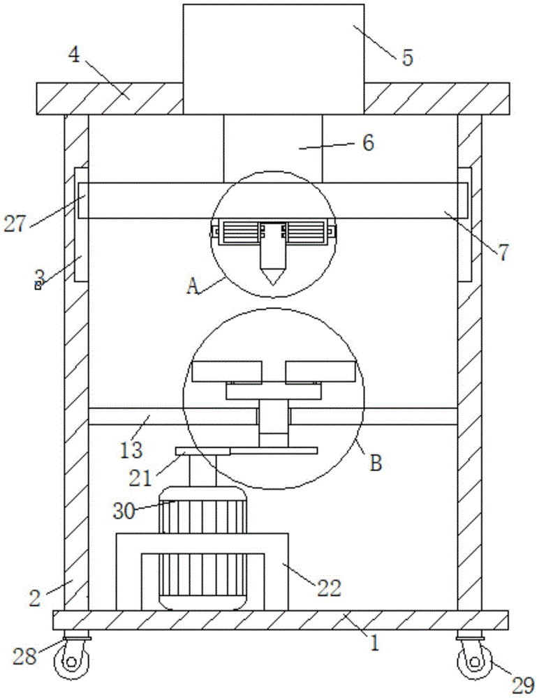
图1是本实用新型的一种注塑件毛刺去除装置的整体结构剖面示意图;1 is a schematic cross-sectional view of the overall structure of a burr removal device for injection molded parts of the present invention;
图2是本实用新型的一种注塑件毛刺去除装置的俯视剖面结构示意图;Fig. 2 is a top-view cross-sectional structural schematic diagram of a burr removal device for injection molded parts of the present invention;
图3是本实用新型的一种注塑件毛刺去除装置的A结构放大示意图;3 is an enlarged schematic view of the structure A of a burr removal device for injection molded parts of the present invention;
图4是本实用新型的一种注塑件毛刺去除装置的B结构放大示意图;4 is an enlarged schematic view of the B structure of a burr removal device for an injection molded part of the present invention;
图5是本实用新型的一种注塑件毛刺去除装置的C结构放大示意图;5 is an enlarged schematic view of the structure C of a burr removal device for injection molded parts of the present invention;
图6是本实用新型的一种注塑件毛刺去除装置的D结构放大示意图。6 is an enlarged schematic view of the D structure of a burr removal device for injection molded parts of the present invention.
图中:1、底座;2、侧板;3、第一滑槽;4、横杆;5、伸缩气缸;6、活塞杆;7、移动杆;8、第一夹具;9、活动插销;10、刀具;11、刀具槽;12、凹槽;13、固定板;14、第二夹具;15、第二滑槽;16、第二滑块;17、固定圆台;18、转轴;19、轴承;20、从动齿轮;21、主动齿轮;22、支架;23、连接件;24、合页;25、螺母件;26、螺栓;27、第一滑块;28、轮座;29、自锁万向轮;30、驱动电机。In the figure: 1, base; 2, side plate; 3, first chute; 4, cross bar; 5, telescopic cylinder; 6, piston rod; 7, moving rod; 8, first clamp; 9, movable latch; 10. Tool; 11. Tool slot; 12. Groove; 13. Fixed plate; 14. Second fixture; 15. Second chute; 16. Second sliding block; 17. Fixed round table; 18. Rotating shaft; 19. Bearing; 20, driven gear; 21, driving gear; 22, bracket; 23, connecting piece; 24, hinge; 25, nut piece; 26, bolt; 27, first slider; 28, wheel seat; 29, Self-locking universal wheel; 30. Drive motor.
具体实施方式Detailed ways
以下结合附图对本实用新型的优选实施例进行说明,应当理解,此处所描述的优选实施例仅用于说明和解释本实用新型,并不用于限定本实用新型。The preferred embodiments of the present utility model will be described below with reference to the accompanying drawings. It should be understood that the preferred embodiments described herein are only used to illustrate and explain the present utility model, but not to limit the present utility model.
实施例Example
如图1-6所示,本实用新型一种注塑件毛刺去除装置包括一个底座1,底座1上表面固定连接有两块呈对称设置的侧板2,两块侧板2靠近顶端的相向位置上均开设有第一滑槽3,两个侧板2的上端共同固定连接有一根横杆4,横杆4中部固定安装有伸缩气缸5,伸缩气缸5的输出端活动连接有活塞杆6,活塞杆6下端固定连接有移动杆7,移动杆(7)下端固定连接有一个第一夹具8,第一夹具8内侧壁开设有刀具槽11,刀具槽11内侧壁活动连接有刀具10,刀具10相对外侧壁上开设有凹槽12,第一夹具8上活动连接有两根活动插销9,活动插销9穿过第一夹具8内部且延伸插设于凹槽12内部,两块侧板2靠近底端位置的相向侧壁之间共同固定连接有一块固定板13,固定板13中部固定安装有轴承19,固定板13中心处通过轴承19转动连接有转轴18,转轴18上端固定连接固定圆台17,固定圆台17上表面呈对称设置开设有两个椭圆弧形的第二滑槽15,两个第二滑槽15内均滑动连接有一块第二滑块16,两块第二滑块(16)的上端均延伸至第二滑槽(15)外且固定连接有一个第二夹具(14),转轴18下端固定连接从动齿轮20,底座1的上表面固定连接有一个驱动电机30,驱动电机30的输出端通过联轴器固定连接有一个主动齿轮21,主动齿轮21与从动齿轮20相啮合。As shown in Figures 1-6, a burr removal device for injection molded parts of the present invention includes a base 1, and two symmetrically arranged
移动杆7两侧均连接第一滑块27,两块第一滑块27远离移动杆7的一端分别延伸至两个第一滑槽3内,可以让刀具10能快速上下移动。Both sides of the moving
两个侧板2下端均固定连接有两个轮座28,四个轮座28下端均固定连接自锁万向轮29,可以根据需求调整位置,避免反复搬运。The lower ends of the two
两个第二夹具14外侧壁固定连接螺母件25,螺母件25内部共同螺纹连接有一根螺栓26,两个第二夹具14远离螺母件25的一端均固定连接有连接件23,两个连接件23之间通过合页24转动连接,可以通过螺母件25和螺栓26的松开和拧紧来对加工件进行固定。The outer side walls of the two
第二夹具14均呈半椭圆形装设置,可以对不同规格的加工件进行夹持。The
底座1的上表面固定安装有支架22,支架22的顶端固定连接在驱动电机 30的外侧壁上,可以在电机启动的时候固定电机,防止在电机振动发生意外。A
具体的,本实用新型一种注塑件毛刺去除装置,在使用时,先将加工件放置于第二夹具14内,通过螺栓26和螺母件25的松动和拧紧,来调整第二夹具 14内部夹持面积的大小,进而可以对不同加工件进行固定,在固定完成后再启动驱动电机30,驱动电机30带动主动齿轮21进行转动,主动齿轮21通过与从动齿轮20的啮合传动带动转轴18进行转动,转轴18带动固定圆台17进行同步转动,固定圆台17带动第二夹具14与第二夹具14夹持的加工件进行同步高速转动,此时启动伸缩气缸5,当活塞杆6向下运动时,移动杆7通过第一滑块27快速带动刀具10向下,当刀具10与加工件外侧相抵时,可以快速切割加工件外侧的毛刺,然后通过上升活塞杆6将刀具10远离加工件,通过夹掉第一夹具8上的活动插销9,让活动插销9与刀具10外侧壁上的凹槽12分离,此时跟换打磨刀具10,再通过活塞杆6下压,让打磨刀具10下降与加工件再一次相抵,进行精加工,加工完成后,上升活塞杆6带动打磨刀具10上升,然后关闭驱动电机30,当固定圆台17完全停下时,松开第二夹具14外侧壁螺母件 25中的螺栓26,然后取下加工件。Specifically, the utility model is a burr removal device for injection molded parts. When in use, the workpiece is first placed in the
最后应说明的是:以上所述仅为本实用新型的优选实施例而已,并不用于限制本实用新型,尽管参照前述实施例对本实用新型进行了详细的说明,对于本领域的技术人员来说,其依然可以对前述各实施例所记载的技术方案进行修改,或者对其中部分技术特征进行等同替换。凡在本实用新型的精神和原则之内,所作的任何修改、等同替换、改进等,均应包含在本实用新型的保护范围之内。Finally, it should be noted that the above are only the preferred embodiments of the present invention, and are not intended to limit the present invention. , it is still possible to modify the technical solutions described in the foregoing embodiments, or perform equivalent replacements to some of the technical features. Any modification, equivalent replacement, improvement, etc. made within the spirit and principle of the present invention shall be included in the protection scope of the present invention.
Claims (6)
Priority Applications (1)
| Application Number | Priority Date | Filing Date | Title |
|---|---|---|---|
| CN201922389126.3U CN211760592U (en) | 2019-12-27 | 2019-12-27 | Injection molding burr remove device |
Applications Claiming Priority (1)
| Application Number | Priority Date | Filing Date | Title |
|---|---|---|---|
| CN201922389126.3U CN211760592U (en) | 2019-12-27 | 2019-12-27 | Injection molding burr remove device |
Publications (1)
| Publication Number | Publication Date |
|---|---|
| CN211760592U true CN211760592U (en) | 2020-10-27 |
Family
ID=72979094
Family Applications (1)
| Application Number | Title | Priority Date | Filing Date |
|---|---|---|---|
| CN201922389126.3U Expired - Fee Related CN211760592U (en) | 2019-12-27 | 2019-12-27 | Injection molding burr remove device |
Country Status (1)
| Country | Link |
|---|---|
| CN (1) | CN211760592U (en) |
Cited By (1)
| Publication number | Priority date | Publication date | Assignee | Title |
|---|---|---|---|---|
| CN118455496A (en) * | 2024-05-16 | 2024-08-09 | 南通锐莱新能源技术有限公司 | Deburring device for processing liquid cooling plates |
-
2019
- 2019-12-27 CN CN201922389126.3U patent/CN211760592U/en not_active Expired - Fee Related
Cited By (1)
| Publication number | Priority date | Publication date | Assignee | Title |
|---|---|---|---|---|
| CN118455496A (en) * | 2024-05-16 | 2024-08-09 | 南通锐莱新能源技术有限公司 | Deburring device for processing liquid cooling plates |
Similar Documents
| Publication | Publication Date | Title |
|---|---|---|
| CN203124723U (en) | Milling machine capable of removing casting heads of castings | |
| CN217776499U (en) | Polishing device for casting part nozzle | |
| CN118372155A (en) | A polishing machine for mold manufacturing | |
| CN114260762A (en) | Efficient internal and external synchronous polishing equipment for circular castings | |
| CN202106204U (en) | Numerical control vertical type turning and milling composite machine tool | |
| CN101234437A (en) | A milling method and equipment for arc surface milling of fist part of automobile front axle | |
| CN120861855A (en) | Double-turret double-electric spindle horizontal lathe for machining circumference and two end faces of long shaft | |
| CN221676442U (en) | A flat processing device for machined parts | |
| CN219212758U (en) | Portable clamping device of square foundry goods | |
| CN209954337U (en) | Special automobile spare and accessory part machining center | |
| CN215317590U (en) | A kind of aluminum alloy template edge burr grinding device | |
| CN213970057U (en) | Positioning device for aluminum die castings during machining | |
| CN109623418B (en) | Special automobile spare and accessory part machining center | |
| CN221435952U (en) | Surface finishing device for casting machining | |
| CN222805960U (en) | Quick die change device for machined parts | |
| CN223933326U (en) | A polishing device for easy-to-adjust mechanical processing | |
| CN219853518U (en) | Long external diameter processing is with exempting from abluent processingequipment | |
| CN218802141U (en) | Fixing device for casting machining | |
| CN223277769U (en) | A plate fixture for a surface grinder | |
| CN222449660U (en) | Polishing equipment for mold processing | |
| CN214768125U (en) | Frame stamping workbench | |
| CN221066199U (en) | High-precision die machining fixing device | |
| CN221676660U (en) | A device for removing burrs from flash edges | |
| CN220329810U (en) | Stamping and clamping tool for machining automobile die | |
| CN212496929U (en) | An intermediate deburring equipment |
Legal Events
| Date | Code | Title | Description |
|---|---|---|---|
| GR01 | Patent grant | ||
| GR01 | Patent grant | ||
| CF01 | Termination of patent right due to non-payment of annual fee |
Granted publication date: 20201027 |
|
| CF01 | Termination of patent right due to non-payment of annual fee |