CN211710773U - External air bag device of car - Google Patents
External air bag device of car Download PDFInfo
- Publication number
- CN211710773U CN211710773U CN202020190715.9U CN202020190715U CN211710773U CN 211710773 U CN211710773 U CN 211710773U CN 202020190715 U CN202020190715 U CN 202020190715U CN 211710773 U CN211710773 U CN 211710773U
- Authority
- CN
- China
- Prior art keywords
- airbag
- valve
- gasbag
- baffle
- spring
- Prior art date
- Legal status (The legal status is an assumption and is not a legal conclusion. Google has not performed a legal analysis and makes no representation as to the accuracy of the status listed.)
- Expired - Fee Related
Links
- 230000000903 blocking effect Effects 0.000 abstract description 29
- 238000009423 ventilation Methods 0.000 description 7
- 230000003139 buffering effect Effects 0.000 description 6
- 238000004880 explosion Methods 0.000 description 5
- 238000010248 power generation Methods 0.000 description 5
- 238000010586 diagram Methods 0.000 description 4
- 230000006378 damage Effects 0.000 description 3
- 208000027418 Wounds and injury Diseases 0.000 description 2
- 230000006835 compression Effects 0.000 description 2
- 238000007906 compression Methods 0.000 description 2
- 230000008602 contraction Effects 0.000 description 2
- 238000005516 engineering process Methods 0.000 description 2
- 208000014674 injury Diseases 0.000 description 2
- 238000000034 method Methods 0.000 description 2
- 208000028771 Facial injury Diseases 0.000 description 1
- 206010019196 Head injury Diseases 0.000 description 1
Images



Landscapes
- Air Bags (AREA)
Abstract
本实用新型提供了一种汽车外置安全气囊以及汽车外置安全气囊装置,所述安全气囊包括气囊Ⅰ以及与气囊Ⅰ连接的气囊Ⅱ,所述气囊Ⅰ的一侧与气体发生器的出气口连通,所述气囊Ⅰ的另一侧可通过阀门与气囊Ⅱ连通,所述阀门包括阀门壳体,所述阀门壳体内设置有阀门腔,所述阀门壳体上设置有可与气囊Ⅰ连通的气口Ⅰ,所述阀门腔内设置有用于封堵气口Ⅰ的封堵球,所述封堵球的一侧设置有挡板,所述封堵球与挡板之间设置有弹簧,所述挡板上设置有可与气囊Ⅱ连通的气口Ⅱ。

The utility model provides an automobile external airbag and an automobile external airbag device. The airbag comprises an airbag I and an airbag II connected with the airbag I. One side of the airbag I is connected to an air outlet of a gas generator. The other side of the airbag I can be communicated with the airbag II through a valve, the valve includes a valve housing, a valve cavity is arranged in the valve housing, and a valve that can be communicated with the airbag I is arranged on the valve housing. Air port I, the valve cavity is provided with a blocking ball for blocking the gas port I, one side of the blocking ball is provided with a baffle, and a spring is arranged between the blocking ball and the baffle, and the blocking ball is provided with a spring. The plate is provided with an air port II which can be communicated with the air bag II.
Description
技术领域technical field
本实用新型涉及的是新能源汽车领域,尤其是一种汽车外置安全气囊以及汽车外置安全气囊装置。The utility model relates to the field of new energy vehicles, in particular to an automobile external airbag and an automobile external airbag device.
背景技术Background technique
安全气囊系统是一种被动安全性(见汽车安全性能)的保护系统,它与座椅安全带配合使用,可以为乘员提供有效的防撞保护。在汽车相撞时,汽车安全气囊可使头部受伤率减少25%,面部受伤率减少8 0%左右。The airbag system is a passive safety (see car safety performance) protection system that works in conjunction with seat belts to provide occupants with effective crash protection. In the event of a car collision, car airbags can reduce head injuries by 25% and facial injuries by about 80%.
当汽车在行驶过程中发生碰撞事故时,压力传感器响应将信号传至控制器,控制器继而动作控制气体发生器起动。气体发生器接到信号后引燃气体发生剂,产生大量气体,使气囊袋在极短的时间内迅速展开,在驾驶员或乘员的前部、侧部或顶部形成弹性气垫,吸收冲击能量,从而有效地保护人体头部和胸部,使之免于伤害或减轻伤害程度。When the car crashes while driving, the pressure sensor responds and transmits the signal to the controller, and the controller then acts to control the gas generator to start. After the gas generator receives the signal, the gas generating agent is ignited, and a large amount of gas is generated, so that the airbag bag can be rapidly deployed in a very short time, and an elastic air cushion is formed on the front, side or top of the driver or passenger to absorb the impact energy, So as to effectively protect the human head and chest from injury or reduce the degree of injury.
目前汽车上使用的安全气囊都是安装在驾驶舱内,这种类型的安全气囊不能对车辆起到保护作用,碰撞的能量完全靠汽车的破坏来吸收。这就是现有技术的不足之处。At present, the airbags used in automobiles are all installed in the cockpit. This type of airbags cannot protect the vehicle, and the energy of the collision is completely absorbed by the destruction of the car. This is the inadequacy of the existing technology.
实用新型内容Utility model content
本实用新型针对上述的不足,提供了一种汽车外置安全气囊,当汽车发生碰撞时,气体发生器产生大量的气体,气囊Ⅰ会在较短的时间内张开,立即起到缓冲效果,当气囊Ⅰ内的气压足够大时,气囊Ⅰ内的气体可通过阀门进入气囊Ⅱ,避免了气囊Ⅰ由于其内气压过大发生爆破的现象;此外,还提供了一种汽车外置安全气囊装置,当汽车在行驶过程中发生碰撞时,在汽车与被撞物之间可形成吸能气垫,从而大大减轻汽车碰撞损失,在汽车与行人发生碰撞的事故中也可对行人产生有效的保护作用。Aiming at the above shortcomings, the utility model provides an automobile external airbag. When the automobile collides, the gas generator generates a large amount of gas, and the airbag I will be opened in a relatively short period of time to immediately play a buffering effect. When the air pressure in the airbag I is high enough, the air in the airbag I can enter the airbag II through the valve, which avoids the explosion of the airbag I due to the excessive pressure in the airbag. , When the car collides during the driving process, an energy-absorbing air cushion can be formed between the car and the object to be hit, thereby greatly reducing the collision loss of the car, and it can also effectively protect the pedestrian in the accident of the collision between the car and the pedestrian. .
本实用新型是通过如下技术实现的:一种汽车外置安全气囊,包括气囊Ⅰ以及与气囊Ⅰ连接的气囊Ⅱ,所述气囊Ⅰ的一侧与气体发生器的出气口连通,所述气囊Ⅰ的另一侧可通过阀门与气囊Ⅱ连通,所述阀门包括阀门壳体,所述阀门壳体内设置有阀门腔,所述阀门壳体上设置有可与气囊Ⅰ连通的气口Ⅰ,所述阀门腔内设置有用于封堵气口Ⅰ的封堵球,所述封堵球的一侧设置有挡板,所述封堵球与挡板之间设置有弹簧,所述挡板上设置有可与气囊Ⅱ连通的气口Ⅱ。The utility model is realized by the following technologies: an automobile external airbag, comprising an airbag I and an airbag II connected with the airbag I, one side of the airbag I is communicated with the air outlet of the gas generator, and the airbag I The other side of the valve can be communicated with the airbag II through a valve, the valve includes a valve housing, a valve cavity is arranged in the valve housing, and an air port I that can be communicated with the airbag I is arranged on the valve housing. A blocking ball for blocking the air port I is arranged in the cavity, a baffle is arranged on one side of the blocking ball, a spring is arranged between the blocking ball and the baffle, and a Port II that communicates with the air bag II.
当汽车发生碰撞时,气体发生器产生大量的气体,气囊Ⅰ会在较短的时间内张开,立即起到缓冲效果,随着气囊Ⅰ内的气压逐渐变大,可通过推动封堵球压缩弹簧,气体通过气口Ⅰ进入阀门腔内,进而通过气口Ⅱ进入气囊Ⅱ内,避免了气囊Ⅰ由于其内气压过大发生爆破的现象,气囊Ⅱ张开后可起到全面缓冲的作用;当气囊Ⅱ内的气体与弹簧对封堵球的压力之和大于气囊Ⅰ内的气体对封堵球的压力时,封堵球将气口Ⅰ封堵。当气囊Ⅱ发生意外不能张开时,气囊Ⅰ可通过阀门向外泄气,独立起到缓冲作用。When the car collides, the gas generator generates a large amount of gas, and the airbag I will open in a short time, and immediately play a buffering effect. As the air pressure in the airbag I gradually increases, it can be compressed by pushing the blocking ball. The spring, the gas enters the valve cavity through the air port I, and then enters the air bag II through the air port II, which avoids the explosion of the air bag I due to the excessive pressure in the air bag. When the sum of the pressure of the gas in II and the spring to the blocking ball is greater than the pressure of the gas in the air bag I to the blocking ball, the blocking ball will block the gas port I. When the air bag II cannot be opened in an accident, the air bag I can be deflated outward through the valve to play a buffering role independently.
优选的,所述阀门腔内设置有内螺纹,所述挡板的外圈设置有外螺纹,所述挡板与阀门壳体螺纹连接。通过旋转挡板可控制弹簧的压缩力。Preferably, the valve cavity is provided with internal threads, the outer ring of the baffle is provided with external threads, and the baffle is threadedly connected to the valve housing. The compression force of the spring is controlled by rotating the flapper.
优选的,所述弹簧为塔簧,塔黄在伸缩过程中比较平稳。Preferably, the spring is a tower spring, and the tower is relatively stable during expansion and contraction.
一种汽车外置安全气囊装置,包括设置在保险杠内的气囊室,所述气囊室内设置有气体发生器,所述气体发生器的出气口与气囊Ⅰ的一侧连通,所述气囊Ⅰ的另一侧连接有气囊Ⅱ,所述气囊Ⅰ可通过阀门与气囊Ⅱ连通,所述保险杠上设置有压力传感器,所述压力传感器与控制器连接,所述控制器与气体发生器连接,所述阀门包括阀门壳体,所述阀门壳体内设置有阀门腔,所述阀门壳体上设置有可与气囊Ⅰ连通的气口Ⅰ,所述阀门腔内设置有用于封堵气口Ⅰ的封堵球,所述封堵球的一侧设置有挡板,所述封堵球与挡板之间设置有弹簧,所述挡板上设置有可与气囊Ⅱ连通的气口Ⅱ。An automobile external airbag device comprises an airbag chamber arranged in a bumper, a gas generator is arranged in the airbag chamber, an air outlet of the gas generator is communicated with one side of an airbag I, and the airbag I The other side is connected with an airbag II, the airbag I can be communicated with the airbag II through a valve, a pressure sensor is provided on the bumper, the pressure sensor is connected with the controller, and the controller is connected with the gas generator, so The valve includes a valve housing, a valve cavity is arranged in the valve housing, an air port I that can be communicated with the air bag I is arranged on the valve housing, and a blocking ball for blocking the air port I is arranged in the valve cavity. One side of the blocking ball is provided with a baffle plate, a spring is arranged between the blocking ball and the baffle plate, and an air port II which can be communicated with the airbag II is arranged on the baffle plate.
当汽车在行驶过程中发生碰撞时,保险杠上的压力传感器相应将信号传至控制器,控制器继而动作控制气体发生器起动。气体发生器接到信号后引燃气体发生剂,产生大量气体进入气囊Ⅰ,气囊Ⅰ会带动气囊Ⅱ从保险杠内的气囊室喷出,所述在汽车与被撞物之间可迅速形成吸能气垫,从而大大减轻汽车碰撞损失,在汽车与行人发生碰撞的事故中也可对行人产生有效的保护作用,当气囊Ⅰ内的气压足够大时,气囊Ⅰ内的气体可通过阀门进入气囊Ⅱ,避免了气囊Ⅰ由于其内气压过大发生爆破的现象。When the car collides during driving, the pressure sensor on the bumper transmits the signal to the controller accordingly, and the controller then acts to control the start of the gas generator. After the gas generator receives the signal, the gas generating agent is ignited, and a large amount of gas is generated into the airbag I, and the airbag I will drive the airbag II to eject from the airbag chamber in the bumper. It can provide air cushion, thus greatly reducing the collision loss of the car, and it can also effectively protect the pedestrian in the accident of the collision between the car and the pedestrian. When the air pressure in the airbag I is large enough, the gas in the airbag I can enter the airbag II through the valve. , to avoid the explosion of the air bag I due to the excessive pressure in it.
优选的,所述阀门腔内设置有内螺纹,所述挡板的外圈设置有外螺纹,所述挡板与阀门壳体螺纹连接。通过旋转挡板可控制弹簧的压缩力。Preferably, the valve cavity is provided with internal threads, the outer ring of the baffle is provided with external threads, and the baffle is threadedly connected to the valve housing. The compression force of the spring is controlled by rotating the flapper.
优选的,所述弹簧为塔簧,塔黄在伸缩过程中比较平稳。Preferably, the spring is a tower spring, and the tower is relatively stable during expansion and contraction.
优选的,所述保险杠包括前保险杠和后保险杠。在汽车的前后两端均设置有安全气囊,大大减少了汽车的碰撞损失。Preferably, the bumper includes a front bumper and a rear bumper. Airbags are installed at the front and rear ends of the car, which greatly reduces the collision loss of the car.
通过上述描述可以看出,本申请相对现有技术具有实质性特点和显著的进步。It can be seen from the above description that the present application has substantial features and significant progress over the prior art.
附图说明Description of drawings
图1为汽车外置安全气囊装置的结构示意图;Fig. 1 is a structural schematic diagram of an automobile external airbag device;
图2为图1中阀门的结构示意图;Fig. 2 is the structural representation of the valve in Fig. 1;
图3为电动汽车示意图;Figure 3 is a schematic diagram of an electric vehicle;
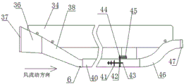
图4为风力发电装置的结构示意图;4 is a schematic structural diagram of a wind power generation device;
图5为不含出风区的导风管结构示意图。FIG. 5 is a schematic structural diagram of an air duct without an air outlet area.
图中, 1为保险杠,2为气囊Ⅰ,3为气囊Ⅱ,4为过阀门,4.1为阀门壳体,4.2为气口Ⅰ,4.3为封堵球,4.4为弹簧,4.5为挡板,4.6为气口Ⅱ,4.7为阀门腔,5为压力传感器,6为气体发生器,7为气囊室,34为车体,35为栅格,36为进风管,37为过滤网,38为交汇管,39为通孔,40为通风管,41为发电扇叶,42为第一齿轮,43为轴,44为第二齿轮,45为发电机,46为出风管,47为滤网。In the figure, 1 is the bumper, 2 is the airbag I, 3 is the airbag II, 4 is the over-valve, 4.1 is the valve housing, 4.2 is the air port I, 4.3 is the blocking ball, 4.4 is the spring, 4.5 is the baffle, 4.6 It is port II, 4.7 is the valve cavity, 5 is the pressure sensor, 6 is the gas generator, 7 is the air bag chamber, 34 is the car body, 35 is the grid, 36 is the air inlet pipe, 37 is the filter screen, and 38 is the intersection pipe , 39 is a through hole, 40 is a ventilation pipe, 41 is a generator fan blade, 42 is a first gear, 43 is a shaft, 44 is a second gear, 45 is a generator, 46 is an air outlet pipe, and 47 is a filter screen.
具体实施方式Detailed ways
下面将结合附图,对本实用新型的技术方案进行清楚、完整地描述。The technical solutions of the present invention will be clearly and completely described below with reference to the accompanying drawings.
实施例1Example 1
一种汽车外置安全气囊,包括气囊Ⅰ2以及与气囊Ⅰ2连接的气囊Ⅱ3,所述气囊Ⅰ2的一侧与气体发生器6的出气口连通,所述气囊Ⅰ2的另一侧可通过阀门4与气囊Ⅱ3连通,所述阀门4包括阀门壳体4.1,所述阀门壳体4.1内设置有阀门腔4.7,所述阀门壳体4.1上设置有可与气囊Ⅰ2连通的气口Ⅰ4.2,所述阀门腔4.7内设置有用于封堵气口Ⅰ4.2的封堵球4.3,所述封堵球4.3的一侧设置有挡板4.5,所述封堵球4.3与挡板4.5之间设置有弹簧4.4,所述挡板4.5上设置有可与气囊Ⅱ3连通的气口Ⅱ4.6,所述阀门腔4.7内设置有内螺纹,所述挡板4.5的外圈设置有外螺纹,所述挡板4.5与阀门壳体4.1螺纹连接,所述弹簧4.4为塔簧。所述气囊Ⅰ2与气体发生器6的出气口的连通处不漏气,所述气囊Ⅰ2与气囊Ⅱ3的连接处不漏气。An automobile external airbag, comprising an airbag I2 and an airbag II3 connected with the airbag I2, one side of the airbag I2 is communicated with the air outlet of the
当汽车发生碰撞时,气体发生器产生大量的气体,气囊Ⅰ2会在较短的时间内张开,立即起到缓冲效果,随着气囊Ⅰ2内的气压逐渐变大,可通过推动封堵球4.3压缩弹簧4.4,气体通过气口Ⅰ4.2进入阀门腔4.7内,进而通过气口Ⅱ4.6进入气囊Ⅱ3内,避免了气囊Ⅰ2由于其内气压过大发生爆破的现象,气囊Ⅱ3张开后可起到全面缓冲的作用;当气囊Ⅱ3内的气体与弹簧4.4对封堵球4.3的压力之和大于气囊Ⅰ2内的气体对封堵球4.3的压力时,封堵球4.3将气口Ⅰ4.2封堵。当气囊Ⅱ3发生意外不能张开时,气囊Ⅰ2可通过阀门4向外泄气,独立起到缓冲作用。When the car collides, the gas generator produces a large amount of gas, the airbag I2 will open in a short time, and immediately play a buffering effect. Compress the spring 4.4, the gas enters the valve cavity 4.7 through the air port I4.2, and then enters the airbag II3 through the air port II4.6, which avoids the explosion of the airbag I2 due to excessive internal pressure. The function of comprehensive buffering; when the sum of the pressure of the gas in the airbag II3 and the spring 4.4 to the blocking ball 4.3 is greater than the pressure of the gas in the airbag I2 to the blocking ball 4.3, the blocking ball 4.3 blocks the air port I4.2. When the air bag II3 cannot be opened by accident, the air bag I2 can be deflated outward through the valve 4 to play a buffering role independently.
实施例2Example 2
一种汽车外置安全气囊装置,包括设置在保险杠1内的气囊室7,所述气囊室7内设置有气体发生器6,所述气体发生器6的出气口与气囊Ⅰ2的一侧连通,所述气囊Ⅰ2的另一侧连接有气囊Ⅱ3,所述气囊Ⅰ2可通过阀门4与气囊Ⅱ3连通,所述保险杠1上设置有压力传感器5,所述压力传感器5与控制器连接,所述控制器与气体发生器6连接,所述阀门4包括阀门壳体4.1,所述阀门壳体4.1内设置有阀门腔4.7,所述阀门壳体4.1上设置有可与气囊Ⅰ2连通的气口Ⅰ4.2,所述阀门腔4.7内设置有用于封堵气口Ⅰ4.2的封堵球4.3,所述封堵球4.3的一侧设置有挡板4.5,所述封堵球4.3与挡板4.5之间设置有弹簧4.4,所述挡板4.5上设置有可与气囊Ⅱ3连通的气口Ⅱ4.6,所述阀门腔4.7内设置有内螺纹,所述挡板4.5的外圈设置有外螺纹,所述挡板4.5与阀门壳体4.1螺纹连接,所述弹簧4.4为塔簧,所述保险杠1包括前保险杠和后保险杠。在汽车的前后两端均设置有安全气囊,大大减少了汽车的碰撞损失。An automobile external airbag device includes an airbag chamber 7 arranged in the bumper 1, the airbag chamber 7 is provided with a
当汽车在行驶过程中发生碰撞时,保险杠1上的压力传感器5相应将信号传至控制器,控制器继而动作控制气体发生器6起动,气体发生器6接到信号后引燃气体发生剂,产生大量气体进入气囊Ⅰ2,气囊Ⅰ2会带动气囊Ⅱ3从保险杠1内的气囊室7喷出,在汽车与被撞物之间可迅速形成吸能气垫,从而大大减轻汽车碰撞损失,在汽车与行人发生碰撞的事故中也可对行人产生有效的保护作用,当气囊Ⅰ2内的气压足够大时,气囊Ⅰ2内的气体可通过阀门4进入气囊Ⅱ3,避免了气囊Ⅰ2由于其内气压过大发生爆破的现象。在正常状态下,所述气囊Ⅰ2和气囊Ⅱ3均设置在保险杠1上的气囊室7内,当发生碰撞时,气囊Ⅰ2可带动气囊Ⅱ3从气囊室7内喷出。所述气囊Ⅰ2与气体发生器6的出气口的连通处不漏气,所述气囊Ⅰ2与气囊Ⅱ3的连接处不漏气。When the car collides during driving, the
所述压力传感器5与控制器连接,所述控制器控制气体发生器6动作等技术特征与现有技术中的压力传感器与控制器连接以及控制器控制气体发生器动作的控制方式完全一致,在此不在赘述。优选的,压力传感器5的型号为NS-TH2,所述控制器为车载ECU。The
实施例3Example 3
作为一个独立的实施例,本实施例公开了一种具有外置安全气囊装置的电动汽车,所述电动汽车包括车体34,所述车体的前端设置有前保险杠,所述前保险杠上设置有上述实施例2中的安全气囊装置,此外,所述电动汽车上还设置有风力发电装置,所述风力发电装置包括发电机45、导风管;发电机45通过整流器与蓄电池充电器连接,蓄电池充电器与车载蓄电池连接,所述导风管固定在车体34上,所述导风管包括依次设置的进风区、交汇区、发电区和出风区。As an independent embodiment, this embodiment discloses an electric vehicle with an external airbag device, the electric vehicle includes a
所述的进风区包括设置在汽车前端的保险杠1上的栅格35处的进风管36,进风管36为锥形,在进风管36的进风口设置过滤网37,所述的进风管36为两个,呈V形设置。The air intake area includes an
所述发电区包括通风管40,在通风管40内设置多组同轴的发电扇叶41,在轴43的后端设置有第一齿轮42,第一齿轮42与第二齿轮44啮合,第二齿轮44设置在发电机45的转轴上且与转轴同步转动,发电扇叶41为三组,沿风流动方向依次为第一发电扇叶组、第二发电扇叶组、第三发电扇叶组,其中第一发电扇叶组的直径小于第二发电扇叶组的直径,第二发电扇叶组的直径小于第三发电扇叶组的直径。The power generation area includes a
所述的交汇区包括交汇管38,交汇管38分别与进风管36和通风管40连通,且在交汇管38的底部设置有通孔39,交汇管38的通孔39设置在交汇管38靠近通风管40的一端。The intersection area includes the
两个进风管36的出风口与交汇区的交汇管38连通,交汇管38的横截面为Y形,且交汇管38与进风管36连接处高于交汇管38与通风管40连接处。锥形的进风管36靠近交汇管38一端的直径小于进风管36进风一端的直径,且进风管36向下倾斜,交汇管38靠近进风管36一端的直径为a,交汇管38靠近通风管40一端的直径为b,a>b。The air outlets of the two
所述的出风区设置出风管46,出风管46与通风管40连通,且所述的出风管46的纵切面为S形。在出风管46的出口处设置可拆卸滤网47。The air outlet area is provided with an
上述的具体实施方式仅仅是本实用新型的两种具体实施方式,而不是全部的实施方式。基于上述的实施方式,本领域技术人员在没有做出创造性劳动前提下所获得的所有其他实施方式,都属于本实用新型保护的范围。The above-mentioned specific embodiments are only two specific embodiments of the present invention, rather than all the embodiments. Based on the above-mentioned embodiments, all other embodiments obtained by those skilled in the art without creative work fall within the protection scope of the present invention.
Claims (7)
Priority Applications (1)
| Application Number | Priority Date | Filing Date | Title |
|---|---|---|---|
| CN202020190715.9U CN211710773U (en) | 2020-02-21 | 2020-02-21 | External air bag device of car |
Applications Claiming Priority (1)
| Application Number | Priority Date | Filing Date | Title |
|---|---|---|---|
| CN202020190715.9U CN211710773U (en) | 2020-02-21 | 2020-02-21 | External air bag device of car |
Publications (1)
| Publication Number | Publication Date |
|---|---|
| CN211710773U true CN211710773U (en) | 2020-10-20 |
Family
ID=72825840
Family Applications (1)
| Application Number | Title | Priority Date | Filing Date |
|---|---|---|---|
| CN202020190715.9U Expired - Fee Related CN211710773U (en) | 2020-02-21 | 2020-02-21 | External air bag device of car |
Country Status (1)
| Country | Link |
|---|---|
| CN (1) | CN211710773U (en) |
Cited By (1)
| Publication number | Priority date | Publication date | Assignee | Title |
|---|---|---|---|---|
| CN119870828A (en) * | 2025-02-28 | 2025-04-25 | 胜代机械(山东)有限公司 | Special tool for grabbing and welding bucket rod box of loader |
-
2020
- 2020-02-21 CN CN202020190715.9U patent/CN211710773U/en not_active Expired - Fee Related
Cited By (1)
| Publication number | Priority date | Publication date | Assignee | Title |
|---|---|---|---|---|
| CN119870828A (en) * | 2025-02-28 | 2025-04-25 | 胜代机械(山东)有限公司 | Special tool for grabbing and welding bucket rod box of loader |
Similar Documents
| Publication | Publication Date | Title |
|---|---|---|
| CN103786681B (en) | School vehicle active-type child safety airbag apparatus and control method thereof | |
| CN201626368U (en) | Passenger car airbag system based on pedestrian protection | |
| CN108275110A (en) | A kind of anti-breakdown formula front double gasbag and its control method | |
| CN109204218A (en) | A kind of children's armchair safety air bag and the children's seat for installing the air bag | |
| CN107719282A (en) | A kind of frontal crash of vehicles energy-absorbing protection structure | |
| CN201472300U (en) | Reusable car security airbag | |
| CN205890819U (en) | Double -deck air bag in side | |
| CN105253088A (en) | Vehicle safety belt use method | |
| CN200995659Y (en) | External safety gasbag cushion for vehicle | |
| CN216034243U (en) | A vehicle front active buffer airbag device | |
| CN209719507U (en) | An airbag module and child safety seat | |
| CN201002575Y (en) | Safety gasbag device for automobile | |
| CN205801023U (en) | There is the automotive seat of air bag | |
| CN204354984U (en) | Auto use chair and corresponding automobile | |
| CN204020790U (en) | A kind of device of automobile external safety air bag | |
| CN102765366A (en) | Pedestrian air bag system and automobile | |
| CN203739830U (en) | Active type child safety air bag device for school buses | |
| CN203305948U (en) | Novel multi-protection auxiliary safety air bag of automobile | |
| CN101844533A (en) | Headrest for automobile seat | |
| CN205059523U (en) | Automotive active safety systems's supplementary safety device | |
| CN203093973U (en) | A car side collision protection device | |
| CN205059507U (en) | Prevent high temperature car air bag | |
| CN108688611A (en) | The hood and vehicle of vehicle | |
| CN110843714B (en) | A kind of delayed detonation of automobile airbag and control method thereof | |
| CN205059522U (en) | Safety belt is initiatively protected to gasbag formula for car |
Legal Events
| Date | Code | Title | Description |
|---|---|---|---|
| GR01 | Patent grant | ||
| GR01 | Patent grant | ||
| CF01 | Termination of patent right due to non-payment of annual fee | ||
| CF01 | Termination of patent right due to non-payment of annual fee |
Granted publication date: 20201020 |