CN211708649U - A table structure for a vertical milling machine - Google Patents
A table structure for a vertical milling machine Download PDFInfo
- Publication number
- CN211708649U CN211708649U CN202020005886.XU CN202020005886U CN211708649U CN 211708649 U CN211708649 U CN 211708649U CN 202020005886 U CN202020005886 U CN 202020005886U CN 211708649 U CN211708649 U CN 211708649U
- Authority
- CN
- China
- Prior art keywords
- wall
- working surface
- pedestal
- fixedly connected
- milling machine
- Prior art date
- Legal status (The legal status is an assumption and is not a legal conclusion. Google has not performed a legal analysis and makes no representation as to the accuracy of the status listed.)
- Expired - Fee Related
Links
Images
Landscapes
- Machine Tool Units (AREA)
Abstract
Description
技术领域technical field
本实用新型属于铣床相关技术领域,具体涉及一种立式铣床用工作台结构。The utility model belongs to the technical field of milling machines, in particular to a worktable structure for a vertical milling machine.
背景技术Background technique
铣床是一种用途广泛的机床,在铣床上可以加工平面、沟槽、分齿零件、螺旋形表面及各种曲面,此外,还可用于对回转体表面、内孔加工及进行切断工作等,铣床在工作时,工件装在工作台上,铣刀旋转为主运动,辅以工作台或铣头的进给运动,工件即可获得所需的加工表面,因此,在铣床加工过程中,铣床用工作台对工件进行固定,是铣床加工工作中重要的部件。Milling machine is a kind of machine tool with a wide range of uses. It can process planes, grooves, toothed parts, helical surfaces and various curved surfaces. In addition, it can also be used for machining surfaces of revolving bodies, inner holes and cutting work. When the milling machine is working, the workpiece is mounted on the worktable, and the rotation of the milling cutter is the main movement, supplemented by the feed movement of the worktable or the milling head, and the workpiece can obtain the required machining surface. Fixing the workpiece with the worktable is an important part in the machining work of the milling machine.
现有的铣床用工作台技术存在以下问题:现有的铣床用工作台在实际的生产加工的应用中,还存在着一定的不足之处,加工工件放置在工作台上,当工件质量较重时,不易对工件进行角度调整,并且,现有的铣床加工工作台并未设置有储物柜,不能对加工过程中的器具零件进行安放归纳,在对工件打磨加工时,工作台上易积累大量打磨垃圾不易进行清洗,实用性能较低。The existing workbench technology for milling machines has the following problems: the existing workbenches for milling machines still have certain shortcomings in the actual production and processing applications. It is not easy to adjust the angle of the workpiece, and the existing milling machine processing table is not equipped with a locker, so it is impossible to place and summarize the appliance parts in the processing process. When the workpiece is polished and processed, it is easy to accumulate on the table. A large amount of grinding waste is not easy to clean, and the practical performance is low.
实用新型内容Utility model content
本实用新型的目的在于提供一种立式铣床用工作台结构,以解决上述背景技术中提出的现有的铣床用工作台在加工时,当工件质量较重时,不易对工件进行角度调整,并且,现有的铣床加工工作台并未设置有储物柜,不能对加工过程中的器具零件进行安放归纳,在对工件打磨加工时,工作台上易积累大量打磨垃圾不易进行清洗的问题。The purpose of this utility model is to provide a worktable structure for a vertical milling machine, so as to solve the problem that when the existing worktable for a milling machine proposed in the above-mentioned background technology is processed, it is difficult to adjust the angle of the workpiece when the quality of the workpiece is heavy. In addition, the existing milling machine processing table is not provided with a locker, and the appliance parts in the processing process cannot be placed and summarized. When grinding and processing the workpiece, a large amount of grinding waste is easily accumulated on the table and is difficult to clean.
为实现上述目的,本实用新型提供如下技术方案:一种立式铣床用工作台结构,包括收集盘和台座,所述收集盘安装在台座的上端外壁上,所述台座靠左右两侧的下端外壁上设置有储物柜,所述收集盘和台座之间通过滑道固定连接,所述收集盘的上端外壁上设置有工作面,所述工作面的中心处外壁上设置有转盘,所述工作面的上端外壁上设置有限位装置,所述限位装置和工作面之间通过滑槽固定连接,所述工作面的右端外壁上设置有固定块,所述台座的上端外壁内部设置有固定孔,所述固定孔和固定块之间通过固定杆固定连接,所述收集盘的下端外壁上设置有滑杆,所述收集盘的上端外壁上设置有扣接板,所述扣接板的内部设置有收集槽,所述限位装置上设置有限位架,所述限位架的下端外壁上设置有滑座,所述滑座的下端外壁上设置有滑块,所述限位架的内部设置有挤压杆,所述挤压杆的下端外壁上设置有挤压块,所述转盘的正下方设置有螺纹杆,所述螺纹杆和转盘之间通过转座固定连接,所述螺纹杆的下端和收集槽的内壁固定连接。In order to achieve the above purpose, the present utility model provides the following technical solutions: a workbench structure for a vertical milling machine, comprising a collection tray and a pedestal, the collection tray is mounted on the outer wall of the upper end of the pedestal, and the pedestal rests on the lower ends of the left and right sides. A storage cabinet is arranged on the outer wall, the collection tray and the pedestal are fixedly connected by a slideway, a working surface is arranged on the outer wall of the upper end of the collection plate, and a turntable is arranged on the outer wall at the center of the working surface. A limiting device is arranged on the outer wall of the upper end of the working surface, the limiting device and the working surface are fixedly connected by a chute, a fixing block is arranged on the outer wall of the right end of the working surface, and a fixing block is arranged inside the outer wall of the upper end of the pedestal. The fixing hole and the fixing block are fixedly connected by a fixing rod, a sliding rod is provided on the outer wall of the lower end of the collection tray, and a buckle plate is arranged on the outer wall of the upper end of the collection tray. A collection groove is arranged inside, a limit frame is arranged on the limit device, a slide seat is arranged on the outer wall of the lower end of the limit frame, a slider is arranged on the outer wall of the lower end of the slide seat, and the limit frame is provided with a sliding block. An extrusion rod is arranged inside, an extrusion block is arranged on the outer wall of the lower end of the extrusion rod, and a threaded rod is arranged directly under the turntable. The lower end of the rod is fixedly connected with the inner wall of the collecting tank.
优选的,所述滑道共设置有两个,两个所述滑道均为T形状结构,所述固定孔均匀的分布在两个所述滑道之间的台座上。Preferably, there are two slideways in total, both of which are T-shaped structures, and the fixing holes are evenly distributed on the pedestal between the two slideways.
优选的,所述储物柜共设置有两个,两个所述储物柜的内部设置有储物槽,所述储物槽靠下侧的前端设置有挡板。Preferably, there are two storage cabinets in total, storage slots are arranged inside the two storage cabinets, and a baffle plate is arranged at the front end of the storage slot on the lower side.
优选的,所述挤压杆的最下端贯穿限位架的内部,所述挤压杆和挤压块之间通过焊接的方式固定连接。Preferably, the lowermost end of the extrusion rod penetrates the interior of the limiting frame, and the extrusion rod and the extrusion block are fixedly connected by welding.
优选的,所述滑杆共设置有两个,两个所述滑杆均为T形状结构,两个所述滑杆和台座之间通过滑道固定连接。Preferably, there are two sliding bars in total, both of which are T-shaped structures, and the two sliding bars and the pedestal are fixedly connected by a slideway.
优选的,所述工作面的下端内部设置有扣槽,所述扣接板和工作面之间通过扣槽固定连接,所述工作面和收集槽之间通过滑槽呈相通状态。Preferably, the lower end of the working surface is provided with a buckle groove, the buckle plate and the working surface are fixedly connected through the buckle groove, and the working surface and the collecting groove are in a state of communication through the chute.
与现有铣床用工作台技术相比,本实用新型提供了一种立式铣床用工作台结构,具备以下有益效果:Compared with the existing workbench technology for milling machines, the utility model provides a workbench structure for vertical milling machines, which has the following beneficial effects:
本实用新型一种立式铣床用工作台结构在现有的工作台结构的基础上进行改进和创新,使得工作台结构在实际的生产加工工作中,具有很好的实用性能,本实用新型一种立式铣床用工作台结构主要是由台座、滑道、储物柜、固定孔、固定杆、固定块、收集盘、工作面、限位装置、转盘以及限位架等结构共同组成,在进行加工工作时,将需要加工的工件放置到工作面上,通过限位装置在滑槽中的移动,来对工件进行固定,通过均为T形状结构的滑杆和滑道的共同作用,使得收集盘和台座之间能够稳定的进行滑动,从而对工作面上的工件位置进行调整,调整完成后,利用固定杆、固定块以及台座上的固定孔对收集盘和工作面进行固定,当待加工的工件质量较重时,可将工件放置在转盘上,利用转盘、转座以及螺纹杆的共同作用,方便对工件进行角度调整,通过储物柜内部的储物槽,可以方便对加工时所需的各种零件进行存放,便于拿取,并且,工作面和收集槽之间通过滑槽呈相通状态,这样可以确保在加工工作中产生的碎屑垃圾等物通过滑槽渗透进收集槽中,待工作结束后,可以对收集槽内部的垃圾进行清理,本实用新型一种立式铣床用工作台结构操作简单,使用方便,具有很好的实用性能。The worktable structure of the vertical milling machine of the utility model is improved and innovated on the basis of the existing worktable structure, so that the worktable structure has good practical performance in the actual production and processing work. The structure of the workbench for a vertical milling machine is mainly composed of a pedestal, a slide, a locker, a fixed hole, a fixed rod, a fixed block, a collection plate, a working surface, a limit device, a turntable and a limit frame. When processing work, place the workpiece to be processed on the working surface, and fix the workpiece through the movement of the limit device in the chute. The collection tray and the pedestal can slide stably to adjust the position of the workpiece on the working surface. After the adjustment is completed, use the fixing rod, the fixing block and the fixing hole on the pedestal to fix the collection tray and the working surface. When the quality of the workpiece to be processed is heavy, the workpiece can be placed on the turntable, and the joint action of the turntable, the turntable and the threaded rod is used to facilitate the angle adjustment of the workpiece. The various parts required are stored for easy access, and the working surface and the collection tank are in a state of communication through the chute, which ensures that debris and other materials generated during the processing work penetrate into the collection tank through the chute In the middle, after the work is finished, the garbage inside the collection tank can be cleaned up. The worktable for a vertical milling machine of the utility model has a simple structure, is convenient to use, and has good practical performance.
附图说明Description of drawings
附图用来提供对本实用新型的进一步理解,并且构成说明书的一部分,与本实用新型的实施例一起用于解释本实用新型,并不构成对本实用新型的限制,在附图中:The accompanying drawings are used to provide a further understanding of the present utility model, and constitute a part of the specification, and are used to explain the present utility model together with the embodiments of the present utility model, and do not constitute a limitation to the present utility model. In the accompanying drawings:
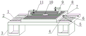
图1为本实用新型提出的一种立式铣床用工作台结构立体结构示意图;Fig. 1 is the three-dimensional structure schematic diagram of the worktable structure for a kind of vertical milling machine proposed by the utility model;
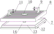
图2为本实用新型提出的一种立式铣床用工作台结构收集盘装配结构示意图;Figure 2 is a schematic diagram of the assembly structure of a collection tray with a worktable structure for a vertical milling machine proposed by the utility model;
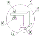
图3为本实用新型提出的限位装置结构示意图;3 is a schematic structural diagram of the limiting device proposed by the utility model;
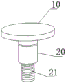
图4为本实用新型提出的转盘装配结构示意图4 is a schematic diagram of the assembly structure of the turntable proposed by the utility model
图中:1、台座;2、滑道;3、储物柜;4、固定孔;5、固定杆;6、固定块;7、收集盘;8、工作面;9、限位装置;10、转盘;11、滑槽;12、滑杆;13、扣接板;14、收集槽;15、限位架;16、滑块;17、滑座;18、挤压块;19、挤压杆;20、转座;21、螺纹杆。In the figure: 1. pedestal; 2. slideway; 3. storage cabinet; 4. fixing hole; 5. fixing rod; 6. fixing block; 7. collecting tray; 8. working surface; 9. limiting device; 10. , turntable; 11, chute; 12, slide bar; 13, buckle plate; 14, collection slot; 15, limit frame; 16, slider; 17, slide seat; 18, extrusion block; 19, extrusion Rod; 20, swivel base; 21, threaded rod.
具体实施方式Detailed ways
下面将结合本实用新型实施例中的附图,对本实用新型实施例中的技术方案进行清楚、完整地描述,显然,所描述的实施例仅仅是本实用新型一部分实施例,而不是全部的实施例。基于本实用新型中的实施例,本领域普通技术人员在没有做出创造性劳动前提下所获得的所有其他实施例,都属于本实用新型保护的范围。The technical solutions in the embodiments of the present utility model will be clearly and completely described below with reference to the accompanying drawings in the embodiments of the present utility model. Obviously, the described embodiments are only a part of the embodiments of the present utility model, rather than all the implementations. example. Based on the embodiments of the present invention, all other embodiments obtained by those of ordinary skill in the art without creative work fall within the protection scope of the present invention.
请参阅图1-4,本实用新型提供一种技术方案:一种立式铣床用工作台结构,包括收集盘7和台座1,收集盘7安装在台座1的上端外壁上,台座1靠左右两侧的下端外壁上设置有储物柜3,储物柜3共设置有两个,两个储物柜3的内部设置有储物槽,储物槽靠下侧的前端设置有挡板,通过储物柜3内部的储物槽可以方便对加工时所需的各种零件进行存放,便于拿取,储物槽前端设置的挡板防止零件往外掉落,收集盘7和台座1之间通过滑道2固定连接,滑道2共设置有两个,两个滑道2均为T形状结构,固定孔4均匀的分布在两个滑道2之间的台座1上,两个T形状结构的滑道2便于收集盘7带动工作面8进行滑动,通过两个滑道2之间的固定孔4的作用,利用固定杆5和固定块6可以将工作面8进行约束固定,收集盘7的上端外壁上设置有工作面8。1-4, the present utility model provides a technical solution: a workbench structure for a vertical milling machine, including a
一种立式铣床用工作台结构,工作面8的下端内部设置有扣槽,扣接板13和工作面8之间通过扣槽固定连接,工作面8和收集槽14之间通过滑槽11呈相通状态,这样可以确保在加工工作中产生的碎屑垃圾等物通过滑槽11渗透进收集槽14中,待工作结束后,对收集槽14内部的垃圾进行清理,工作面8的中心处外壁上设置有转盘10,工作面8的上端外壁上设置有限位装置9,限位装置9和工作面8之间通过滑槽11固定连接,工作面8的右端外壁上设置有固定块6,台座1的上端外壁内部设置有固定孔4,固定孔4和固定块6之间通过固定杆5固定连接,收集盘7的下端外壁上设置有滑杆12,滑杆12共设置有两个,两个滑杆12均为T形状结构,两个滑杆12和台座1之间通过滑道2固定连接,通过均为T形状结构的滑杆12和滑道2的共同作用,使得收集盘7和台座1之间能够稳定的进行滑动,从而对工作面8上的工件位置进行调整,收集盘7的上端外壁上设置有扣接板13,扣接板13的内部设置有收集槽14,限位装置9上设置有限位架15,限位架15的下端外壁上设置有滑座17,滑座17的下端外壁上设置有滑块16,限位架15的内部设置有挤压杆19,挤压杆19的最下端贯穿限位架15的内部,挤压杆19和挤压块18之间通过焊接的方式固定连接,这样可以确保挤压杆19和挤压块18之间连接稳定牢固,通过挤压杆19和挤压块18的共同作用,可以将所需加工的工件进行挤压固定,挤压杆19的下端外壁上设置有挤压块18,转盘10的正下方设置有螺纹杆21,螺纹杆21和转盘10之间通过转座20固定连接,螺纹杆21的下端和收集槽14的内壁固定连接。A workbench structure for a vertical milling machine, the lower end of the working
本实用新型的工作原理及使用流程:本实用新型安装好过后,本实用新型一种立式铣床用工作台结构主要是由台座1、滑道2、储物柜3、固定孔4、固定杆5、固定块6、收集盘7、工作面8、限位装置9、转盘10以及限位架15等结构共同组成,其中,限位装置9主要是由限位架15、滑块16、挤压杆19和挤压块18等结构组成,在进行加工工作时,将所需要加工的工件放置到工作面8上,通过限位装置9下端的滑块16在滑槽11中的移动,将工件固定在工作面8上,然后,通过均为T形状结构的滑杆12和滑道2,将收集盘7在台座1上进行滑动,对工作面8上的工件位置进行调整固定,调整完成后,将收集盘7上固定块6内部的固定杆5插进固定孔4中,将收集盘7和工作面8进行固定,当待加工的工件质量较重时,可将工件放置在转盘10上,利用转盘10对工件进行角度调整,其中,转盘10通过转座20下端内部的螺纹槽的作用,可以在螺纹杆21外壁上转动,调节转盘10的高度,在需要用到转盘10进行工作时,转盘10高于工作面8,在不需要用到转盘10,可将转盘10调至低于工作面8,确保加工工作的准确安全,在加工工作结束后,在加工工作中产生的碎屑等物会通过滑槽11渗透进收集槽14中,将收集盘7利用滑杆12从台座1上抽出,可以对收集槽14中的垃圾进行处理,本实用新型一种立式铣床用工作台结构具有很高的使用价值。The working principle and use process of the utility model: after the utility model is installed, the workbench structure for a vertical milling machine of the present utility model is mainly composed of a
尽管已经示出和描述了本实用新型的实施例,对于本领域的普通技术人员而言,可以理解在不脱离本实用新型的原理和精神的情况下可以对这些实施例进行多种变化、修改、替换和变型,本实用新型的范围由所附权利要求及其等同物限定。Although the embodiments of the present invention have been shown and described, it will be understood by those skilled in the art that various changes and modifications can be made to these embodiments without departing from the principles and spirit of the present invention , alternatives and modifications, the scope of the present invention is defined by the appended claims and their equivalents.
Claims (6)
Priority Applications (1)
| Application Number | Priority Date | Filing Date | Title |
|---|---|---|---|
| CN202020005886.XU CN211708649U (en) | 2020-01-03 | 2020-01-03 | A table structure for a vertical milling machine |
Applications Claiming Priority (1)
| Application Number | Priority Date | Filing Date | Title |
|---|---|---|---|
| CN202020005886.XU CN211708649U (en) | 2020-01-03 | 2020-01-03 | A table structure for a vertical milling machine |
Publications (1)
| Publication Number | Publication Date |
|---|---|
| CN211708649U true CN211708649U (en) | 2020-10-20 |
Family
ID=72820405
Family Applications (1)
| Application Number | Title | Priority Date | Filing Date |
|---|---|---|---|
| CN202020005886.XU Expired - Fee Related CN211708649U (en) | 2020-01-03 | 2020-01-03 | A table structure for a vertical milling machine |
Country Status (1)
| Country | Link |
|---|---|
| CN (1) | CN211708649U (en) |
-
2020
- 2020-01-03 CN CN202020005886.XU patent/CN211708649U/en not_active Expired - Fee Related
Similar Documents
| Publication | Publication Date | Title |
|---|---|---|
| CN217290575U (en) | Novel numerical control planer type milling machine structure | |
| CN214291918U (en) | A turning and grinding machine for machining | |
| CN117583627A (en) | A CNC lathe for high-stability bearing processing | |
| CN211890241U (en) | Grinding device for gear machining | |
| CN218874704U (en) | Vertical machining center workstation | |
| CN220330060U (en) | Milling machine capable of performing elevation treatment | |
| CN211161961U (en) | Bench lathe with garbage collection | |
| CN215699735U (en) | Transmission device for workbench of numerical control milling machine | |
| CN209190370U (en) | A kind of milling machine with self-priming cleaning stationary work-table | |
| CN211135588U (en) | Boring machine with internal circulation cooling system | |
| CN208341860U (en) | A kind of cutter device for hardware pipe fitting | |
| CN222308210U (en) | A machine tool CNC cutting machine convenient for limiting position | |
| CN220388672U (en) | CNC processing frock clamp | |
| CN222740965U (en) | Milling machine for precision manufacturing | |
| CN219543487U (en) | Angle-adjustable planing machine | |
| CN218311071U (en) | Main lead screw anti-sagging and anti-vibration device of gantry milling machine | |
| CN218591842U (en) | Multifunctional double-spindle cutter arranging machine | |
| CN220073804U (en) | A pipe orifice dresser for metal hose processing | |
| CN222244231U (en) | Wood processing is with plane light machine | |
| CN218836735U (en) | Prevent numerical control milling and boring machine that work piece warp | |
| CN206882938U (en) | Numerical control gear milling machine | |
| CN223441646U (en) | Gantry frame of a gantry milling machine | |
| CN221047845U (en) | Numerical control milling machine capable of fixing objects with different volumes | |
| CN222999675U (en) | Cutting device for production of printing equipment parts | |
| CN214517994U (en) | Milling device for straight bevel gear |
Legal Events
| Date | Code | Title | Description |
|---|---|---|---|
| GR01 | Patent grant | ||
| GR01 | Patent grant | ||
| TR01 | Transfer of patent right |
Effective date of registration: 20210105 Address after: No.369 Changhong North Road, Luzhi Town, Wuzhong District, Suzhou City, Jiangsu Province Patentee after: Suzhou sanyide Precision Machinery Co.,Ltd. Address before: Room 1804, building 1, No. 2011, Sunwu Road, Xiangshan street, Taihu National Tourist Resort, Suzhou City, Jiangsu Province Patentee before: Jiangsu Jimo Technology Co.,Ltd. |
|
| TR01 | Transfer of patent right | ||
| CF01 | Termination of patent right due to non-payment of annual fee |
Granted publication date: 20201020 Termination date: 20220103 |
|
| CF01 | Termination of patent right due to non-payment of annual fee |