CN211703093U - A green roof for building sponge cities - Google Patents
A green roof for building sponge cities Download PDFInfo
- Publication number
- CN211703093U CN211703093U CN202020065346.0U CN202020065346U CN211703093U CN 211703093 U CN211703093 U CN 211703093U CN 202020065346 U CN202020065346 U CN 202020065346U CN 211703093 U CN211703093 U CN 211703093U
- Authority
- CN
- China
- Prior art keywords
- water
- water storage
- roof
- storage cavity
- sponge city
- Prior art date
- Legal status (The legal status is an assumption and is not a legal conclusion. Google has not performed a legal analysis and makes no representation as to the accuracy of the status listed.)
- Expired - Fee Related
Links
Images


Classifications
-
- Y—GENERAL TAGGING OF NEW TECHNOLOGICAL DEVELOPMENTS; GENERAL TAGGING OF CROSS-SECTIONAL TECHNOLOGIES SPANNING OVER SEVERAL SECTIONS OF THE IPC; TECHNICAL SUBJECTS COVERED BY FORMER USPC CROSS-REFERENCE ART COLLECTIONS [XRACs] AND DIGESTS
- Y02—TECHNOLOGIES OR APPLICATIONS FOR MITIGATION OR ADAPTATION AGAINST CLIMATE CHANGE
- Y02A—TECHNOLOGIES FOR ADAPTATION TO CLIMATE CHANGE
- Y02A20/00—Water conservation; Efficient water supply; Efficient water use
- Y02A20/108—Rainwater harvesting
-
- Y—GENERAL TAGGING OF NEW TECHNOLOGICAL DEVELOPMENTS; GENERAL TAGGING OF CROSS-SECTIONAL TECHNOLOGIES SPANNING OVER SEVERAL SECTIONS OF THE IPC; TECHNICAL SUBJECTS COVERED BY FORMER USPC CROSS-REFERENCE ART COLLECTIONS [XRACs] AND DIGESTS
- Y02—TECHNOLOGIES OR APPLICATIONS FOR MITIGATION OR ADAPTATION AGAINST CLIMATE CHANGE
- Y02A—TECHNOLOGIES FOR ADAPTATION TO CLIMATE CHANGE
- Y02A40/00—Adaptation technologies in agriculture, forestry, livestock or agroalimentary production
- Y02A40/10—Adaptation technologies in agriculture, forestry, livestock or agroalimentary production in agriculture
- Y02A40/22—Improving land use; Improving water use or availability; Controlling erosion
-
- Y—GENERAL TAGGING OF NEW TECHNOLOGICAL DEVELOPMENTS; GENERAL TAGGING OF CROSS-SECTIONAL TECHNOLOGIES SPANNING OVER SEVERAL SECTIONS OF THE IPC; TECHNICAL SUBJECTS COVERED BY FORMER USPC CROSS-REFERENCE ART COLLECTIONS [XRACs] AND DIGESTS
- Y02—TECHNOLOGIES OR APPLICATIONS FOR MITIGATION OR ADAPTATION AGAINST CLIMATE CHANGE
- Y02B—CLIMATE CHANGE MITIGATION TECHNOLOGIES RELATED TO BUILDINGS, e.g. HOUSING, HOUSE APPLIANCES OR RELATED END-USER APPLICATIONS
- Y02B10/00—Integration of renewable energy sources in buildings
- Y02B10/30—Wind power
-
- Y—GENERAL TAGGING OF NEW TECHNOLOGICAL DEVELOPMENTS; GENERAL TAGGING OF CROSS-SECTIONAL TECHNOLOGIES SPANNING OVER SEVERAL SECTIONS OF THE IPC; TECHNICAL SUBJECTS COVERED BY FORMER USPC CROSS-REFERENCE ART COLLECTIONS [XRACs] AND DIGESTS
- Y02—TECHNOLOGIES OR APPLICATIONS FOR MITIGATION OR ADAPTATION AGAINST CLIMATE CHANGE
- Y02E—REDUCTION OF GREENHOUSE GAS [GHG] EMISSIONS, RELATED TO ENERGY GENERATION, TRANSMISSION OR DISTRIBUTION
- Y02E10/00—Energy generation through renewable energy sources
- Y02E10/70—Wind energy
- Y02E10/72—Wind turbines with rotation axis in wind direction
-
- Y—GENERAL TAGGING OF NEW TECHNOLOGICAL DEVELOPMENTS; GENERAL TAGGING OF CROSS-SECTIONAL TECHNOLOGIES SPANNING OVER SEVERAL SECTIONS OF THE IPC; TECHNICAL SUBJECTS COVERED BY FORMER USPC CROSS-REFERENCE ART COLLECTIONS [XRACs] AND DIGESTS
- Y02—TECHNOLOGIES OR APPLICATIONS FOR MITIGATION OR ADAPTATION AGAINST CLIMATE CHANGE
- Y02E—REDUCTION OF GREENHOUSE GAS [GHG] EMISSIONS, RELATED TO ENERGY GENERATION, TRANSMISSION OR DISTRIBUTION
- Y02E10/00—Energy generation through renewable energy sources
- Y02E10/70—Wind energy
- Y02E10/728—Onshore wind turbines
-
- Y—GENERAL TAGGING OF NEW TECHNOLOGICAL DEVELOPMENTS; GENERAL TAGGING OF CROSS-SECTIONAL TECHNOLOGIES SPANNING OVER SEVERAL SECTIONS OF THE IPC; TECHNICAL SUBJECTS COVERED BY FORMER USPC CROSS-REFERENCE ART COLLECTIONS [XRACs] AND DIGESTS
- Y02—TECHNOLOGIES OR APPLICATIONS FOR MITIGATION OR ADAPTATION AGAINST CLIMATE CHANGE
- Y02E—REDUCTION OF GREENHOUSE GAS [GHG] EMISSIONS, RELATED TO ENERGY GENERATION, TRANSMISSION OR DISTRIBUTION
- Y02E70/00—Other energy conversion or management systems reducing GHG emissions
- Y02E70/30—Systems combining energy storage with energy generation of non-fossil origin
-
- Y—GENERAL TAGGING OF NEW TECHNOLOGICAL DEVELOPMENTS; GENERAL TAGGING OF CROSS-SECTIONAL TECHNOLOGIES SPANNING OVER SEVERAL SECTIONS OF THE IPC; TECHNICAL SUBJECTS COVERED BY FORMER USPC CROSS-REFERENCE ART COLLECTIONS [XRACs] AND DIGESTS
- Y02—TECHNOLOGIES OR APPLICATIONS FOR MITIGATION OR ADAPTATION AGAINST CLIMATE CHANGE
- Y02P—CLIMATE CHANGE MITIGATION TECHNOLOGIES IN THE PRODUCTION OR PROCESSING OF GOODS
- Y02P60/00—Technologies relating to agriculture, livestock or agroalimentary industries
- Y02P60/12—Technologies relating to agriculture, livestock or agroalimentary industries using renewable energies, e.g. solar water pumping
Landscapes
- Cultivation Of Plants (AREA)
Abstract
本实用新型涉及一种建设海绵城市用的绿色屋顶,包括屋顶本体,屋顶本体顶部设置有种植区,种植区的底部设置有蓄水腔,蓄水腔的内壁设置有防渗水层,屋顶本体的上表面的周边设置有集水槽,集水槽的顶部设置有过滤网,集水槽的底部设置有若干与蓄水腔连通的导流孔,种植区的顶部设置有用于浇灌的喷洒装置。本实用新型具有对雨水进行收集再循环利用的优点。
The utility model relates to a green roof for building a sponge city, which comprises a roof body, a planting area is arranged on the top of the roof body, a water storage cavity is arranged at the bottom of the planting area, and an anti-seepage layer is arranged on the inner wall of the water storage cavity. There is a water collecting tank on the periphery of the upper surface of the water collecting tank, the top of the water collecting tank is provided with a filter screen, the bottom of the water collecting tank is provided with a number of diversion holes communicating with the water storage cavity, and the top of the planting area is provided with a sprinkler for watering. The utility model has the advantages of collecting and recycling rainwater.
Description
技术领域technical field
本实用新型涉及建筑的技术领域,尤其是涉及一种建设海绵城市用的绿色屋顶。The utility model relates to the technical field of construction, in particular to a green roof for building a sponge city.
背景技术Background technique
屋顶本体绿化可以广泛地理解为在各类古今建筑物、构筑物、城围、桥梁(立交桥)等的屋顶本体、露台、天台、阳台或大型人工假山的山体上进行造园,种植树木花卉的统称。Roof greening can be widely understood as a general term for gardening and planting trees and flowers on the roof bodies, terraces, rooftops, balconies or large artificial hills of various ancient and modern buildings, structures, city walls, bridges (overpasses), etc. .
屋顶本体绿化对增加城市绿地面积,改善日趋恶化的人类生存环境空间;改善城市高楼大厦林立,改善众多道路的硬质铺装而取代的自然土地和植物的现状;开拓人类绿化空间,建造田园城市,改善人民的居住条件,提高生活质量,以及对美化城市环境,改善生态效应有着极其重要的意义。Roof greening can increase the area of urban green space and improve the deteriorating human living environment space; improve urban high-rise buildings, improve the status quo of natural land and plants replaced by hard pavement of many roads; open up human green space and build a garden city It is of great significance to improve people's living conditions, improve the quality of life, and beautify the urban environment and improve the ecological effect.
屋顶本体绿化不仅是绿地向空中发展,节约土地、开拓城市空间的有效办法,也是建筑艺术与园林艺术的完美结合,在保护城市环境,提高人居环境质量方面更是起着不可忽视的作用。Roof greening is not only an effective way to develop green space into the air, save land and open up urban space, but also a perfect combination of architectural art and garden art. It plays an important role in protecting the urban environment and improving the quality of the living environment.
在公告号为CN205591440U的中国实用新型专利中公开了一种绿色屋顶本体结构,包括屋顶本体和设置在屋顶本体周边的女儿墙,女儿墙内的屋顶本体上设置有防水层,防水层上设置有土工膜,土工膜上设置有轻石层,轻石层上部设置有第一土工布,第一土工布上设置有有机肥,有机肥上种植有绿色植物,屋顶本体的排水部周边还设置有阻挡避让部。A green roof body structure is disclosed in Chinese utility model patent publication number CN205591440U, which includes a roof body and a parapet arranged around the roof body. A waterproof layer is provided on the roof body in the parapet, and a waterproof layer is provided on the waterproof layer. Geomembrane, a pumice layer is arranged on the geomembrane, a first geotextile is arranged on the upper part of the pumice layer, an organic fertilizer is arranged on the first geomembrane, green plants are planted on the organic fertilizer, and a drainage part of the roof body is also arranged around the periphery. Blocking dodges.
上述中的现有技术方案存在以下缺陷:此种绿色屋顶本体结构不能够贮存雨水,当降雨量不足时,需要使用自来水等其它水资源对绿色屋顶本体上的植被进行浇灌,未能很好的利用降雨带来的水资源。The above-mentioned prior art scheme has the following defects: this kind of green roof body structure cannot store rainwater, and when the rainfall is insufficient, it is necessary to use other water resources such as tap water to water the vegetation on the green roof body, which is not very good. Utilize water resources from rainfall.
实用新型内容Utility model content
针对现有技术存在的不足,本实用新型的目的是提供一种建设海绵城市用的绿色屋顶,其具有对雨水进行收集再循环利用的优点。In view of the deficiencies of the prior art, the purpose of the present invention is to provide a green roof for building a sponge city, which has the advantage of collecting and recycling rainwater.
本实用新型的上述实用新型目的是通过以下技术方案得以实现的:The above-mentioned utility model purpose of the present utility model is achieved through the following technical solutions:
一种建设海绵城市用的绿色屋顶,包括屋顶本体,所述屋顶本体顶部设置有种植区,所述种植区的底部设置有蓄水腔,所述蓄水腔的内壁设置有防渗水层,所述屋顶本体的上表面的周边设置有集水槽,所述集水槽的顶部设置有过滤网,所述集水槽的底部设置有若干与蓄水腔连通的导流孔,所述种植区的顶部设置有用于浇灌的喷洒装置。A green roof for building a sponge city, comprising a roof body, a planting area is arranged at the top of the roof body, a water storage cavity is arranged at the bottom of the planting area, and an anti-seepage layer is arranged on the inner wall of the water storage cavity, The periphery of the upper surface of the roof body is provided with a water collection tank, the top of the water collection tank is provided with a filter screen, the bottom of the water collection tank is provided with a number of diversion holes that communicate with the water storage cavity, and the top of the planting area is provided with A sprinkler for watering is provided.
通过采用上述技术方案,下雨天,雨水经过滤网过滤后杂质较少,雨水在集水槽内汇集,通过导流孔流入蓄水腔内储蓄,然后通过喷洒装置用于种植区里的植被浇灌,其能够对雨水进行收集再循环使用,增加水资源的利用率,蓄水腔内的防渗水层能够防止雨水渗透出蓄水腔。By adopting the above technical solution, in rainy days, the rainwater has less impurities after being filtered by the filter screen, and the rainwater is collected in the sump, flows into the water storage cavity through the diversion hole for storage, and then is used for the vegetation watering in the planting area through the spraying device. The rainwater can be collected and recycled to increase the utilization rate of water resources, and the anti-seepage layer in the water storage cavity can prevent rainwater from penetrating out of the water storage cavity.
本实用新型在一较佳示例中可以进一步配置为:所述蓄水腔的底部设置有防潮膜,所述屋顶本体的底部设置有保温垫,所述保温垫的底部设置有保护层。In a preferred example of the present invention, it can be further configured as follows: the bottom of the water storage cavity is provided with a moisture-proof membrane, the bottom of the roof body is provided with a thermal pad, and the bottom of the thermal pad is provided with a protective layer.
通过采用上述技术方案,防潮膜具备良好的防潮功能,能够很好地减小蓄水腔内的雨水对室内墙壁的影响,保温垫能够起到保温作用,保证在冬天时,室内不受蓄水腔的影响,能够有较高的温度,保护层能够保护保温垫不受损坏,提高居民居住的舒适度。By adopting the above technical solutions, the moisture-proof membrane has a good moisture-proof function, which can well reduce the impact of rainwater in the water storage cavity on the indoor walls, and the thermal insulation pad can play a role in thermal insulation, ensuring that the room is not protected from water storage in winter. The impact of the cavity can have a higher temperature, and the protective layer can protect the thermal insulation pad from damage and improve the living comfort of the residents.
本实用新型在一较佳示例中可以进一步配置为:所述种植区的顶部设置有喷洒管,所述喷洒管的一端封闭,所述喷洒管的另一端与蓄水腔连通,所述喷洒管朝向种植区方向开设有若干喷洒孔,若干所述喷洒孔的出口端设置有雾化喷头,所述喷洒管上远离喷洒孔的一端连通有水泵。In a preferred example of the present invention, it can be further configured as follows: the top of the planting area is provided with a spray pipe, one end of the spray pipe is closed, the other end of the spray pipe is communicated with the water storage cavity, and the spray pipe A number of spray holes are opened in the direction of the planting area, the outlet ends of the spray holes are provided with atomizing nozzles, and the end of the spray pipe that is far away from the spray holes is connected with a water pump.
通过采用上述技术方案,水泵将蓄水腔内的雨水抽送到喷洒管内,雨水在雾化喷头的雾化下,对种植区的植被浇灌效果好,节约水资源。By adopting the above technical solution, the water pump pumps the rainwater in the water storage cavity to the spray pipe, and the rainwater is atomized by the atomizing nozzle, which has a good effect on vegetation watering in the planting area and saves water resources.
本实用新型在一较佳示例中可以进一步配置为:所述导流孔内套设有过滤器。In a preferred example of the present invention, it can be further configured that a filter is sleeved inside the guide hole.
通过采用上述技术方案,雨水首先经过滤网的过滤,杂质降低,再经过滤器的进一步过滤,雨水的干净程度进一步提高,保障蓄水腔内的水质清洁,保证对植被的浇灌的稳定性。By adopting the above technical solution, the rainwater is first filtered by the filter screen, the impurities are reduced, and then further filtered by the filter, the cleanness of the rainwater is further improved, the water quality in the water storage cavity is guaranteed to be clean, and the stability of the irrigation of the vegetation is ensured.
本实用新型在一较佳示例中可以进一步配置为:所述屋顶本体外设置有与蓄水腔底部连通的溢流管。In a preferred example of the present invention, an overflow pipe that communicates with the bottom of the water storage cavity is provided outside the roof body.
通过采用上述技术方案,在降雨量较大时,蓄水腔内的雨水容易集满,此时溢流管能够起到泄流的作用,防止蓄水腔内的雨水过多发生倒灌。By adopting the above technical solution, when the rainfall is large, the rainwater in the water storage cavity is easy to be filled up, and the overflow pipe can play the role of draining at this time, preventing the backflow of excessive rainwater in the water storage cavity.
本实用新型在一较佳示例中可以进一步配置为:所述溢流管位于蓄水腔的顶部侧壁,所述房屋的底部周侧壁设置有排水渠,所述溢流管远离蓄水腔的一端通向排水渠。In a preferred example of the present invention, it can be further configured that: the overflow pipe is located on the top side wall of the water storage cavity, the bottom peripheral side wall of the house is provided with a drainage channel, and the overflow pipe is far away from the water storage cavity One end leads to the drain.
通过采用上述技术方案,经溢流管排出的雨水通向排水渠,溢流至排水渠水能够用来浇花,保证水资源的充分利用。By adopting the above technical solution, the rainwater discharged through the overflow pipe leads to the drainage channel, and the water overflowing to the drainage channel can be used for watering flowers, so as to ensure the full utilization of water resources.
本实用新型在一较佳示例中可以进一步配置为:所述蓄水腔的顶部设置有进水口,所述蓄水腔的侧壁底部设置有出水口,所述进水口与出水口均设置有密封塞。In a preferred example of the present invention, it can be further configured as follows: the top of the water storage cavity is provided with a water inlet, the bottom of the side wall of the water storage cavity is provided with a water outlet, and both the water inlet and the water outlet are provided with a water inlet. sealing plug.
通过采用上述技术方案,当蓄水腔内雨水量不足时,通过进水口可以向蓄水腔内人工注水,保证蓄水腔内的水充足;通过出水口将蓄水腔内雨水排出,方便对蓄水腔的清洁。By adopting the above technical solution, when the amount of rainwater in the water storage cavity is insufficient, water can be manually injected into the water storage cavity through the water inlet to ensure sufficient water in the water storage cavity; Cleaning of the reservoir.
本实用新型在一较佳示例中可以进一步配置为:所述屋顶本体的顶部设置有风力发电机,所述风力发电机与水泵电性连接。In a preferred example of the present invention, it can be further configured as follows: a wind power generator is arranged on the top of the roof body, and the wind power generator is electrically connected with the water pump.
通过采用上述技术方案,风力发电机能够利用风力发电,将风能转化为电能,然后给水泵提供所需的电源。By adopting the above technical solutions, the wind turbine can generate electricity by using wind, convert the wind energy into electric energy, and then provide the required power for the water pump.
综上所述,本实用新型包括以下至少一种有益技术效果:To sum up, the present utility model includes at least one of the following beneficial technical effects:
下雨天,雨水经过滤网过滤后杂质较少,雨水在集水槽内汇集,然后通过导流孔流入蓄水腔内储蓄以用于种植区里的植被浇灌,其能够对雨水进行收集再循环使用,增加水资源的利用率;On rainy days, the rainwater has less impurities after being filtered by the filter screen. The rainwater is collected in the water collection tank, and then flows into the water storage cavity through the diversion hole for storage in the planting area. It can collect and recycle the rainwater for use. , increase the utilization rate of water resources;
水泵将蓄水腔内的雨水抽送到喷洒管内,雨水在雾化喷头的雾化下,对种植区的植被浇灌效果好,节约水资源;The water pump pumps the rainwater in the water storage cavity to the spray pipe, and the rainwater is atomized by the atomizing nozzle, which has a good effect on the vegetation in the planting area and saves water resources;
风力发电机能够利用风力发电,将风能转化为电能,然后给水泵提供所需的电源。Wind turbines use wind power to generate electricity, convert the wind energy into electricity, and then provide the required power to the pumps.
附图说明Description of drawings
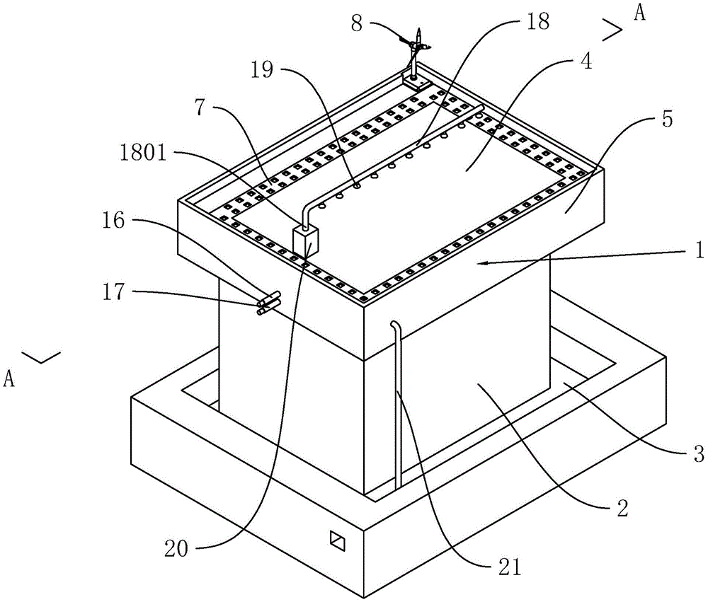
图1是本实施例的整体示意图;Fig. 1 is the overall schematic diagram of this embodiment;
图2是本实施例中局部爆炸视图;Fig. 2 is a partial exploded view in this embodiment;
图3是图2中A部分的放大示意图;Fig. 3 is the enlarged schematic diagram of A part in Fig. 2;
图4是沿图1中A-A线的剖视图;Fig. 4 is a sectional view along line A-A in Fig. 1;
图5是图4中B部分的放大示意图;Fig. 5 is the enlarged schematic diagram of part B in Fig. 4;
图6是沿图2中B-B线的剖视图。FIG. 6 is a cross-sectional view taken along line B-B in FIG. 2 .
图中,1、屋顶本体;2、房屋;3、排水渠;4、种植区;5、女儿墙;6、集水槽;7、过滤网;8、风力发电机;9、蓄水腔;10、防渗水层;11、导流孔;12、过滤器;13、防潮膜;14、保温垫;15、保护层;16、进水口;17、出水口;18、喷洒管;1801、连通管;19、雾化喷头;20、水泵;21、溢流管。In the figure, 1. Roof body; 2. House; 3. Drainage channel; 4. Planting area; 5. Parapet; 6. Water collection tank; 7. Filter screen; 8. Wind turbine; 9. Water storage cavity; 10 , water-proof layer; 11, diversion hole; 12, filter; 13, moisture-proof membrane; 14, insulation pad; 15, protective layer; 16, water inlet; 17, water outlet; 18, spray pipe; 1801, communication pipe; 19, atomizing nozzle; 20, water pump; 21, overflow pipe.
具体实施方式Detailed ways
以下结合附图对本实用新型作进一步详细说明。The present utility model will be described in further detail below in conjunction with the accompanying drawings.
参照图1,为本实用新型公开的一种建设海绵城市用的绿色屋顶,包括屋顶本体1,屋顶本体1的底部是房屋2,房屋2的底部周侧壁环绕开设有排水渠3。Referring to FIG. 1 , the utility model discloses a green roof for building a sponge city, including a
参照图2,屋顶本体1的顶壁设置有用于种植的种植区4,种植区4覆盖屋顶本体1的整个顶壁。屋顶本体1顶壁外沿一体成型有女儿墙5。屋顶本体1顶部开设有集水槽6,集水槽6位于屋顶本体1内靠近女儿墙5内壁的一侧,集水槽6的顶部设置有过滤网7,过滤网7位于集水槽6的顶部且与屋顶本体1一体成型。Referring to FIG. 2 , the top wall of the
屋顶本体1顶壁的角落铰接固定有风力发电机8,风力发电机8位于靠近女儿墙5内壁的一侧,风力发电机8与室内的蓄电池(图中未示出)电性连接。A
参照图3和图4,种植区4的底部开设有蓄水腔9,蓄水腔9位于屋顶本体1内部远离风力发电机8的一侧,蓄水腔9呈矩形状,蓄水腔9的内壁粘接固定有防渗水层10,防渗水层10由聚合物水泥基防水涂料制成,其具有具有透气不渗水、柔韧性好、耐候性强、施工简便等特点。位于蓄水腔9顶部的集水槽6的底部竖直开设有三个导流孔11,导流孔 11呈圆柱状,导流孔11连通集水槽6以及蓄水腔9。导流孔11内嵌设有与导流孔11同轴的过滤器12,过滤器12呈圆柱状。3 and 4, the bottom of the
参照图4和图5,蓄水腔9的底部外壁依次粘接固定有防潮膜13,防潮膜13由PE 高分子材料制成,其是具有防潮、隔音和平衡的作用。防潮膜13远离蓄水腔9的一侧壁粘接固定有保温垫14,保温垫14为聚氨酯泡沫,具其有重量轻、可加工性好、致密性高、保温隔热效果好的特点。保温垫14远离防潮膜13的一侧壁粘接固定有保护层15,保护层15 由特制混凝土制成,其硬度大,保护性能好。4 and 5 , the bottom outer wall of the
屋顶本体1的外侧壁位于远离风力发电机8的一侧开设有进水口16,进水口16呈圆柱状,进水口16的轴线与屋顶本体1的外侧壁垂直,进水口16与蓄水腔9连通,进水口 16位于蓄水腔9内壁的顶部。进水口16的底部开设有出水口17,出水口17位于蓄水腔9 内壁的底部,出水口17呈圆柱状,出水口17与蓄水腔9连通,出水口17的轴线与进水口 16轴线平行,进水口16与出水口17内均塞有密封塞,进水口16与出水口17位于同一竖直轴线上。The outer side wall of the
屋顶本体1的顶部固定有喷洒管18,喷洒管18呈圆柱状,喷洒管18的轴线与进水口16平行,喷洒管18的周侧壁焊接有若干雾化喷头19,雾化喷头19与喷洒管18连通,雾化喷头19的开口朝向种植区4。喷洒管18的一端封闭,喷洒管18的另一端连通有连通管1801,连通管1801远离喷洒管18的一端穿入蓄水腔9的内部并与蓄水腔9的底部连通。连通管1801位于屋顶本体1顶壁的一侧连通有水泵20。The top of the
参照图5和图6,屋顶本体1的外侧壁位于远离风力发电机8以及进水口16的一侧粘结固定有水平设置的溢流管21,溢流管21与蓄水腔9的内部连通,溢流管21的横截面呈圆柱状,溢流管21远离蓄水腔9的一端穿出蓄水腔9后竖直向下弯折与排水渠3连通,使得溢流管21呈“L”字状。5 and 6 , the outer side wall of the
本实施例的实施原理为:雨天雨水落到屋顶本体1的种植区4后,经过滤网7的过滤后流入集水槽6中,经导流孔11内的过滤器12的进一步过滤后流入蓄水腔9中储蓄;蓄水腔9中储蓄的雨水通过喷洒管18连接到种植区4循环利用,当蓄水腔9内的雨水积满后,雨水可以通过溢流管21及时的排到排水渠3中。The implementation principle of the present embodiment is as follows: after rain falls on the
本具体实施方式的实施例均为本实用新型的较佳实施例,并非依此限制本实用新型的保护范围,故:凡依本实用新型的结构、形状、原理所做的等效变化,均应涵盖于本实用新型的保护范围之内。The embodiments of this specific embodiment are all preferred embodiments of the present invention, and are not intended to limit the protection scope of the present invention, therefore: all equivalent changes made according to the structure, shape and principle of the present invention are It should be covered within the protection scope of the present invention.
Claims (8)
Priority Applications (1)
| Application Number | Priority Date | Filing Date | Title |
|---|---|---|---|
| CN202020065346.0U CN211703093U (en) | 2020-01-13 | 2020-01-13 | A green roof for building sponge cities |
Applications Claiming Priority (1)
| Application Number | Priority Date | Filing Date | Title |
|---|---|---|---|
| CN202020065346.0U CN211703093U (en) | 2020-01-13 | 2020-01-13 | A green roof for building sponge cities |
Publications (1)
| Publication Number | Publication Date |
|---|---|
| CN211703093U true CN211703093U (en) | 2020-10-20 |
Family
ID=72823208
Family Applications (1)
| Application Number | Title | Priority Date | Filing Date |
|---|---|---|---|
| CN202020065346.0U Expired - Fee Related CN211703093U (en) | 2020-01-13 | 2020-01-13 | A green roof for building sponge cities |
Country Status (1)
| Country | Link |
|---|---|
| CN (1) | CN211703093U (en) |
Cited By (2)
| Publication number | Priority date | Publication date | Assignee | Title |
|---|---|---|---|---|
| CN112663723A (en) * | 2020-12-11 | 2021-04-16 | 上海累土建筑设计咨询有限公司 | Circulating water curtain based on reclaimed water reuse |
| CN113982201A (en) * | 2021-10-14 | 2022-01-28 | 河海大学 | Green roof design system of habitat based on rainwater purification and utilization |
-
2020
- 2020-01-13 CN CN202020065346.0U patent/CN211703093U/en not_active Expired - Fee Related
Cited By (2)
| Publication number | Priority date | Publication date | Assignee | Title |
|---|---|---|---|---|
| CN112663723A (en) * | 2020-12-11 | 2021-04-16 | 上海累土建筑设计咨询有限公司 | Circulating water curtain based on reclaimed water reuse |
| CN113982201A (en) * | 2021-10-14 | 2022-01-28 | 河海大学 | Green roof design system of habitat based on rainwater purification and utilization |
Similar Documents
| Publication | Publication Date | Title |
|---|---|---|
| CN104652597B (en) | The method of work of the relatively low ecotecture of maintenance cost | |
| CN215254015U (en) | Ecological roof greening circulating water structure for sponge city | |
| CN203487719U (en) | Rainwater collection, greening and thermal insulation roof | |
| CN210395880U (en) | Take afforestation roof structure that rainwater was collected | |
| CN208354221U (en) | A kind of water-saving filling apparatus of full-automatic afforestation | |
| CN207362969U (en) | Rainwater garden | |
| CN213268306U (en) | Greening roof for sponge city | |
| CN107447930A (en) | Water collection type Green Roof structure | |
| CN213897834U (en) | Sponge city green roof structure | |
| CN212656311U (en) | A rainwater collection and utilization device for roof gardens | |
| CN211396316U (en) | Green ecological roof structure | |
| CN106069380A (en) | A kind of booth cooling system and method | |
| CN209990033U (en) | Sponge urban water storage type roof garden structure | |
| CN210928810U (en) | Structure of multi-functional roof grassland afforestation roof | |
| CN218912003U (en) | Roof structure is planted with environmental protection to sponge city | |
| CN208675884U (en) | A kind of Ecological Road | |
| CN214178216U (en) | Intelligent light roof greening system | |
| CN210659391U (en) | Environment-friendly ecological house | |
| CN214430513U (en) | Roof greening device for sponge city planning | |
| CN208039645U (en) | A kind of roof rain water garden system based on sponge city | |
| CN210117864U (en) | A roof garden that can avoid rain soaking | |
| CN210685198U (en) | Water storage planting roof structure | |
| CN207211539U (en) | Water collection type Green Roof structure | |
| CN214126316U (en) | A roof greening waterproof device | |
| CN221276730U (en) | An environmentally friendly green building structure |
Legal Events
| Date | Code | Title | Description |
|---|---|---|---|
| GR01 | Patent grant | ||
| GR01 | Patent grant | ||
| CF01 | Termination of patent right due to non-payment of annual fee | ||
| CF01 | Termination of patent right due to non-payment of annual fee |
Granted publication date: 20201020 |