CN211682851U - A mortar mixing and conveying device - Google Patents
A mortar mixing and conveying device Download PDFInfo
- Publication number
- CN211682851U CN211682851U CN202020167224.2U CN202020167224U CN211682851U CN 211682851 U CN211682851 U CN 211682851U CN 202020167224 U CN202020167224 U CN 202020167224U CN 211682851 U CN211682851 U CN 211682851U
- Authority
- CN
- China
- Prior art keywords
- conveying
- stirring
- mortar
- barrel
- conveying device
- Prior art date
- Legal status (The legal status is an assumption and is not a legal conclusion. Google has not performed a legal analysis and makes no representation as to the accuracy of the status listed.)
- Expired - Fee Related
Links
Images


Landscapes
- On-Site Construction Work That Accompanies The Preparation And Application Of Concrete (AREA)
Abstract
本实用新型涉及建筑机械技术领域,尤其涉及一种灰浆搅拌输送装置。本实用新型提供的灰浆搅拌输送装置,包括安装架、搅拌机构、输送机构和快拆机构,搅拌机构架设安装架上,搅拌机构用于盛放并搅拌灰浆,搅拌机构的底部设置有开口朝下的料筒出料口;输送机构通过料筒出料口与搅拌机构相连通,用于输送经过搅拌机构搅拌后的浆料;搅拌机构通过快拆机构与输送机构可拆卸的固定连接。该灰浆搅拌输送装置,通过采用快拆机构能够实现料筒机构和输送机构的快速拆装,便于分别对料筒机构和输送机构进行内部清洗,从而防止发生砂浆堵泵现象,提高工作效率。
The utility model relates to the technical field of construction machinery, in particular to a mortar stirring and conveying device. The mortar stirring and conveying device provided by the utility model comprises a mounting frame, a stirring mechanism, a conveying mechanism and a quick release mechanism. The stirring mechanism is erected on the mounting frame, and the stirring mechanism is used to hold and stir the mortar. The bottom of the stirring mechanism is provided with an opening facing downward. The outlet of the barrel; the conveying mechanism is communicated with the stirring mechanism through the outlet of the barrel, and is used to transport the slurry stirred by the stirring mechanism; the stirring mechanism is detachably and fixedly connected to the conveying mechanism through the quick release mechanism. The mortar stirring and conveying device can realize the quick disassembly and assembly of the barrel mechanism and the conveying mechanism by adopting the quick disassembly mechanism, which facilitates the internal cleaning of the barrel mechanism and the conveying mechanism respectively, thereby preventing the phenomenon of mortar blocking the pump and improving the work efficiency.
Description
技术领域technical field
本实用新型涉及建筑机械技术领域,尤其涉及一种灰浆搅拌输送装置。The utility model relates to the technical field of construction machinery, in particular to a mortar stirring and conveying device.
背景技术Background technique
灰浆由水泥、石灰、石膏等胶凝材料加水搅拌而成的浆状混合料,主要用于建筑领域的粉刷或灌缝。由于灰浆搅拌完成后在短时间内易与空气反应而发生凝固,因此,在现有的灰浆搅拌装置中,通常需要设置压力泵以便于输送灰浆。然而,如若使用压力泵进行泵送,容易使得料筒和压力泵清洗困难,久而久之,砂浆凝固容易造成堵泵的现象,使得灰浆搅拌装置工作不连续,工作效率低。Mortar is a paste-like mixture formed by mixing cement, lime, gypsum and other cementitious materials with water. It is mainly used for plastering or grouting in the construction field. Since the mortar is easy to react with air and solidify in a short time after the completion of stirring, in the existing mortar stirring device, a pressure pump is usually required to facilitate the delivery of the mortar. However, if the pressure pump is used for pumping, it is easy to make the cleaning of the barrel and the pressure pump difficult. Over time, the solidification of the mortar will easily cause the phenomenon of blocking the pump, which makes the mortar stirring device work discontinuously and the work efficiency is low.
因此,亟待需要一种新型的灰浆搅拌输送装置以解决上述问题。Therefore, there is an urgent need for a new type of mortar stirring and conveying device to solve the above problems.
实用新型内容Utility model content
本实用新型的目的在于提供一种灰浆搅拌输送装置,以解决现有技术中灰浆搅拌装置清洗困难的问题。The purpose of the utility model is to provide a mortar stirring and conveying device to solve the problem of difficulty in cleaning the mortar stirring device in the prior art.
为实现上述目的,提供以下技术方案:To achieve the above purpose, the following technical solutions are provided:
一种灰浆搅拌输送装置,包括:A mortar stirring and conveying device, comprising:
安装架;Mount;
搅拌机构,架设在所述安装架上,所述搅拌机构用于盛放并搅拌灰浆,所述搅拌机构的底部设置有开口朝下的料筒出料口;The stirring mechanism is erected on the mounting frame, the stirring mechanism is used to hold and stir the mortar, and the bottom of the stirring mechanism is provided with a material barrel discharge port with an opening facing downward;
输送机构,通过所述料筒出料口与所述搅拌机构相连通,用于输送经过所述搅拌机构搅拌后的浆料;a conveying mechanism, which is communicated with the stirring mechanism through the discharge port of the barrel, and is used for conveying the slurry stirred by the stirring mechanism;
快拆机构,所述搅拌机构通过所述快拆机构与所述输送机构可拆卸的固定连接。A quick release mechanism, the stirring mechanism is detachably and fixedly connected with the conveying mechanism through the quick release mechanism.
作为灰浆搅拌输送装置的优选方案,所述输送机构包括:As a preferred solution of the mortar stirring and conveying device, the conveying mechanism includes:
料仓,所述料仓上设置有输送进料口和输送出料口,所述输送进料口与所述搅拌机构连通;a material silo, the material silo is provided with a conveying inlet and a conveying outlet, and the conveying inlet is communicated with the stirring mechanism;
送料组件,设置在所述料仓上,用于将所述料仓内的灰浆推送至所述输送出料口;a feeding assembly, arranged on the silo, for pushing the mortar in the silo to the conveying outlet;
作为灰浆搅拌输送装置的优选方案,所述输送机构包括:所述料仓包括:As a preferred solution of the mortar stirring and conveying device, the conveying mechanism includes: the silo includes:
上盖,所述输送进料口设置在所述上盖上;an upper cover, the conveying and feeding port is arranged on the upper cover;
下壳体,其上设置有用于容置灰浆的容纳腔,所述上盖可拆卸地安装在所述下壳体上。The lower casing is provided with an accommodating cavity for accommodating the mortar, and the upper cover is detachably mounted on the lower casing.
作为灰浆搅拌输送装置的优选方案,所述上盖与所述下壳体之间的装配面中间设置有密封垫。As a preferred solution of the mortar stirring and conveying device, a sealing gasket is arranged in the middle of the assembling surface between the upper cover and the lower casing.
作为灰浆搅拌输送装置的优选方案,所述下壳体包括:As a preferred solution of the mortar stirring and conveying device, the lower shell includes:
腹壳,其为两端开口的壳体结构,所述输送出料口设置在所述腹壳的底部;an abdominal shell, which is a shell structure with openings at both ends, and the conveying and discharging port is arranged at the bottom of the abdominal shell;
第一端盖,可拆卸地安装在所述腹壳的一端;a first end cover, detachably mounted on one end of the abdominal shell;
第二端盖,可拆卸地安装在所述腹壳的另一端。A second end cap is detachably mounted on the other end of the abdominal shell.
作为灰浆搅拌输送装置的优选方案,所述输送机构还包括出料口密封组件,能够打开或封闭所述输送出料口;As a preferred solution of the mortar stirring and conveying device, the conveying mechanism further includes a discharge port sealing component, which can open or close the conveying discharge port;
所述出料口密封组件包括:The outlet sealing assembly includes:
密封盖,可移动地设置所述料仓上,以打开或关闭所述输送出料口。A sealing cover is movably arranged on the silo to open or close the delivery outlet.
作为灰浆搅拌输送装置的优选方案,所述送料组件包括:As a preferred solution of the mortar stirring and conveying device, the feeding component includes:
螺旋杆,可转动地设置在所述料仓内;a screw rod, which is rotatably arranged in the silo;
送料驱动件,其驱动端与所述螺旋杆固定连接,所述送料驱动件能够驱动所述螺旋杆转动以将所述料仓内的灰浆推送至所述输送出料口。A feeding driving member, the driving end of which is fixedly connected with the screw rod, and the feeding driving member can drive the screw rod to rotate so as to push the mortar in the silo to the conveying and discharging port.
作为灰浆搅拌输送装置的优选方案,所述搅拌机构包括:As a preferred solution of the mortar stirring and conveying device, the stirring mechanism includes:
料筒,用于盛放灰浆,所述料筒出料口设置在所述料筒的底部且开口朝下设置;a barrel, used to hold the mortar, the outlet of the barrel is arranged at the bottom of the barrel with the opening facing downward;
搅拌组件,设置在所述料筒上,用于对所述料筒内的灰浆进行搅拌。The stirring component is arranged on the barrel, and is used for stirring the mortar in the barrel.
作为灰浆搅拌输送装置的优选方案,所述搅拌组件包括:As a preferred solution of the mortar stirring and conveying device, the stirring assembly includes:
安装板,安装在所述料筒上;a mounting plate, mounted on the barrel;
搅拌件,其第一端可转动地安装在所述安装板上,其第二端能够伸入所述料筒内,且能够推动所述灰浆向下移动;a stirring element, the first end of which is rotatably mounted on the mounting plate, and the second end of which can extend into the material barrel and can push the mortar to move downward;
搅拌驱动件,设置在所述安装板上,所述搅拌驱动件的驱动端与所述搅拌件的第一端固定连接,以驱动所述搅拌件搅拌灰浆。The stirring driving member is arranged on the mounting plate, and the driving end of the stirring driving member is fixedly connected with the first end of the stirring member, so as to drive the stirring member to stir the mortar.
作为灰浆搅拌输送装置的优选方案,所述料筒包括圆筒部和锥筒部,所述锥筒部设置在所述圆筒部的下端且与所述圆筒部相连通,所述料筒出料口设置在所述锥筒部的下端。As a preferred solution of the mortar stirring and conveying device, the barrel includes a cylindrical portion and a conical portion, the conical portion is disposed at the lower end of the cylindrical portion and communicates with the cylindrical portion, and the barrel The discharge port is arranged at the lower end of the cone portion.
作为灰浆搅拌输送装置的优选方案,所述安装架包括;As a preferred solution of the mortar stirring and conveying device, the mounting frame includes;
底座;base;
立柱,多根所述立柱间隔固定设置在所述底座上;uprights, a plurality of the uprights are fixedly arranged on the base at intervals;
托环,固定设置在多根所述立柱上,所述托环的直径小于所述料筒的圆筒部的直径,所述料筒的锥筒部架设在所述托环上。The supporting ring is fixedly arranged on the plurality of the uprights, the diameter of the supporting ring is smaller than the diameter of the cylindrical portion of the material cylinder, and the conical cylindrical portion of the material cylinder is erected on the supporting ring.
作为灰浆搅拌输送装置的优选方案,所述料筒出料口上设置有第一安装法兰,所述输送进料口上设置有第二安装法兰,所述快拆机构包括:As a preferred solution of the mortar stirring and conveying device, the discharge port of the barrel is provided with a first mounting flange, the conveying and feeding port is provided with a second mounting flange, and the quick release mechanism includes:
匚型夹,包括相对设置且连接的第一支臂和第二支臂,且所述第一安装法兰和所述第二安装法兰能均够位于所述第一支臂和所述第二支臂之间;The type clamp includes a first support arm and a second support arm that are oppositely arranged and connected, and the first mounting flange and the second mounting flange can both be located on the first support arm and the second support arm. between the two arms;
锁紧件,螺纹连接于所述第一支臂和所述第二支臂中的一个上,通过旋拧所述锁紧件能够使所述第一安装法兰或所述第二安装法兰抵紧于所述第一支臂和所述第二支臂中的另一个上;A locking piece is screwed on one of the first support arm and the second support arm, and the first mounting flange or the second mounting flange can be made by screwing the locking piece abutting against the other of the first support arm and the second support arm;
棘轮扳手,能够与所述锁紧件相配合,往复转动所述棘轮扳手能够使所述锁紧件转动。The ratchet wrench can be matched with the locking member, and reciprocating rotation of the ratchet wrench can make the locking member rotate.
与现有技术相比,本实用新型的有益效果为:Compared with the prior art, the beneficial effects of the present utility model are:
本实用新型提供的灰浆搅拌输送装置,包括安装架、搅拌机构、输送机构和快拆机构。搅拌机构架设安装架上,搅拌机构用于盛放并搅拌灰浆,搅拌机构的底部设置有开口朝下的料筒出料口;输送机构通过料筒出料口与搅拌机构相连通,用于输送经过搅拌机构搅拌后的浆料;搅拌机构通过快拆机构与输送机构可拆卸的固定连接。该灰浆搅拌输送装置,通过采用快拆机构能够实现料筒机构和输送机构的快速拆装,便于分别对料筒机构和输送机构进行内部清洗,从而防止发生砂浆堵泵现象,提高工作效率。The mortar stirring and conveying device provided by the utility model comprises an installation frame, a stirring mechanism, a conveying mechanism and a quick release mechanism. The stirring mechanism is erected on the installation frame, and the stirring mechanism is used to hold and stir the mortar. The bottom of the stirring mechanism is provided with a barrel outlet with an opening facing downward; the conveying mechanism is communicated with the stirring mechanism through the barrel outlet, which is used for conveying The slurry stirred by the stirring mechanism; the stirring mechanism is detachably and fixedly connected with the conveying mechanism through the quick release mechanism. The mortar stirring and conveying device can realize the quick disassembly and assembly of the barrel mechanism and the conveying mechanism by adopting the quick disassembly mechanism, which facilitates the internal cleaning of the barrel mechanism and the conveying mechanism respectively, thereby preventing the phenomenon of mortar blocking the pump and improving the work efficiency.
附图说明Description of drawings
为了更清楚地说明本实用新型实施例中的技术方案,下面将对本实用新型实施例描述中所需要使用的附图作简单的介绍,显而易见地,下面描述中的附图仅仅是本实用新型的一些实施例,对于本领域普通技术人员来讲,在不付出创造性劳动的前提下,还可以根据本实用新型实施例的内容和这些附图获得其他的附图。In order to illustrate the technical solutions in the embodiments of the present invention more clearly, the following briefly introduces the accompanying drawings used in the description of the embodiments of the present invention. Obviously, the accompanying drawings in the following description are only of the present invention. In some embodiments, for those of ordinary skill in the art, other drawings can also be obtained according to the contents of the embodiments of the present invention and these drawings without creative efforts.
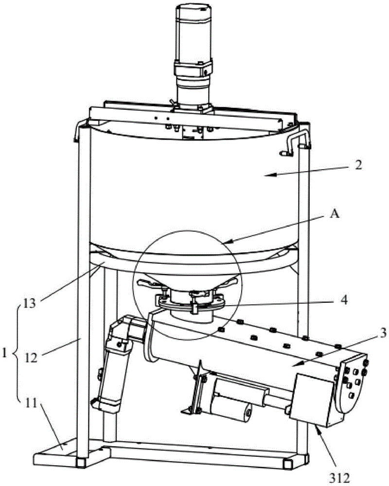
图1为本实用新型实施例提供的灰浆搅拌输送装置的结构示意图;1 is a schematic structural diagram of a mortar stirring and conveying device provided by an embodiment of the present utility model;
图2为图1中A处的放大图;Fig. 2 is the enlarged view of A place in Fig. 1;
图3为本实用新型实施例提供的快拆机构的结构示意图;3 is a schematic structural diagram of a quick release mechanism provided by an embodiment of the present invention;
图4为本实用新型实施例提供的料筒机构的分解示意图;4 is an exploded schematic view of a barrel mechanism provided by an embodiment of the present invention;
图5为本实用新型实施例提供的输送机构的分解示意图。FIG. 5 is an exploded schematic diagram of the conveying mechanism provided by the embodiment of the present invention.
附图标记:Reference number:
1-安装架;11-底座;12-立柱;13-托环;1-mounting frame; 11-base; 12-post; 13-support ring;
2-搅拌机构;21-料筒;211-料筒出料口;2111-第一安装法兰;22-安装板; 23-搅拌件;231-搅拌叶;24-搅拌驱动件;25-提手;2- Stirring mechanism; 21- Barrel; 211- Barrel outlet; 211- First mounting flange; 22- Mounting plate; 23- Stirring piece; 231- Stirring blade; 24- Stirring driving piece; 25- Lifting hand;
3-输送机构;31-上盖;311-输送进料口;3111-第二安装法兰;312-输送出料口;32-下壳体;321-腹壳;322-第一端盖;323-第二端盖;33-螺旋杆;34- 送料驱动件;35-密封盖;36-密封盖驱动件;37-密封垫;38-密封圈;3-conveying mechanism; 31-upper cover; 311-conveying inlet; 3111-second mounting flange; 312-conveying outlet; 32-lower shell; 321-belly shell; 322-first end cover; 323-Second end cover; 33-Screw rod; 34-Feed drive; 35-Sealing cover; 36-Sealing cover drive; 37-Gasket; 38-Sealing ring;
4-快拆机构;41-匚型夹;42-锁紧件;43-棘轮扳手。4- Quick release mechanism; 41- Clamp; 42- Locking piece; 43- Ratchet wrench.
具体实施方式Detailed ways
为了使本领域技术人员更好地理解本实用新型的技术方案,下面结合附图并通过具体实施方式来进一步说明本实用新型的技术方案。In order for those skilled in the art to better understand the technical solutions of the present invention, the technical solutions of the present invention are further described below with reference to the accompanying drawings and through specific embodiments.
在本实用新型的描述中,需要说明的是,术语“上”、“下”、“左”、“右”、“竖直”、“水平”、“内”、“外”等指示的方位或位置关系为基于附图所示的方位或位置关系,或是本产品使用时惯常摆放的方位或位置关系,仅是为了便于描述本实用新型,而不是指示或暗示所指的装置或元件必须具有特定的方位、以特定的方位构造和操作,因此不能理解为对本实用新型的限制。此外,术语“第一”、“第二”仅用于描述目的,或者用于区分不同结构或部件,而不能理解为指示或暗示相对重要性。In the description of the present invention, it should be noted that the orientations indicated by the terms "upper", "lower", "left", "right", "vertical", "horizontal", "inner", "outer", etc. Or the positional relationship is based on the orientation or positional relationship shown in the attached drawings, or the orientation or positional relationship that is usually placed when the product is used, is only for the convenience of describing the present invention, rather than indicating or implying the device or element. It must have a specific orientation, be constructed and operated in a specific orientation, and therefore should not be construed as a limitation of the present invention. Furthermore, the terms "first" and "second" are used for descriptive purposes only or to distinguish different structures or components, and should not be construed to indicate or imply relative importance.
在本实用新型的描述中,需要说明的是,除非另有明确的规定和限定,术语“安装”、“相连”、“连接”应做广义理解,例如,可以是固定连接,也可以是可拆卸连接;可以是机械连接,也可以是电连接;可以是直接相连,也可以通过中间媒介间接相连,可以是两个元件内部的连通。对于本领域的普通技术人员而言,可以具体情况理解上述术语在本实用新型中的具体含义。In the description of the present invention, it should be noted that, unless otherwise expressly specified and limited, the terms "installed", "connected" and "connected" should be understood in a broad sense, for example, it may be a fixed connection or a connectable connection. It can be a mechanical connection or an electrical connection; it can be a direct connection or an indirect connection through an intermediate medium, and it can be the internal communication of the two components. For those of ordinary skill in the art, the specific meanings of the above terms in the present invention can be understood in specific situations.
如图1-图2所示,本实施例提供了一种灰浆搅拌输送装置,包括安装架1、搅拌机构2、输送机构3和快拆机构4。搅拌机构2架设安装架1上,搅拌机构 2用于盛放并搅拌灰浆,搅拌机构2的底部设置有开口朝下的料筒出料口211;输送机构3通过料筒出料口211与搅拌机构2相连通,用于输送经过搅拌机构2 搅拌后的浆料;搅拌机构2通过快拆机构4与输送机构3连通,以实现快速拆装。该灰浆搅拌输送装置,通过采用快拆机构4能够实现料筒机构2和输送机构3的快速拆装,便于分别对料筒机构2和输送机构3进行内部清洗,从而防止发生砂浆堵泵现象,提高工作效率。As shown in FIGS. 1-2 , this embodiment provides a mortar stirring and conveying device, including a mounting frame 1 , a
优选地,如图2结合图5所示,输送机构3包括料仓和送料组件,料仓上设置有输送进料口311和输送出料口312,输送进料口311通过料筒出料口211 与搅拌机构2相连通;送料组件用于将料仓内的灰浆推送至输送出料口312,以实灰浆的送料。Preferably, as shown in FIG. 2 in conjunction with FIG. 5 , the conveying
进一步地,输送机构3的料仓与水平面呈夹角设置,且其上的输送进料口 311朝上,输送出料口312朝下设置,以便于料仓内的灰浆在重力作用下流向输送出料口312。Further, the silo of the conveying
优选地,如图2结合图1所示,料筒机构2包括料筒21,料筒21用于容置灰浆,料筒21包括圆筒部和锥筒部,锥筒部设置在圆筒部的下端且与圆筒部相连通,料筒出料口211设置在锥筒部的下端。Preferably, as shown in FIG. 2 in conjunction with FIG. 1 , the
进一步地,料筒21架设安装架1上,且其上的料筒出料口211朝下悬空设置,料筒21内的灰浆在重力作用下由输送进料口311进入料仓,并从输送出料口312排出。具体而言,该灰浆搅拌输送装置,通过将料筒21和料仓架设在安装架1上,且架在高点位置,然后利用重力进行灰浆的输送,无需采用压力泵进行送料,从而便于对料筒21进行清洗。Further, the
优选地,如图1所示,安装架1包括底座11、立柱12和托环13,多根立柱12间隔固定设置在底座11上;托环13固定设置在多根立柱12上,托环13 的直径小于料筒21的圆筒部的直径,料筒21的锥筒部架设在托环13上,从而实现将料筒21架设在安装架1上。Preferably, as shown in FIG. 1 , the mounting frame 1 includes a base 11 , a
示例性地,立柱12的数量为三根,三根立柱12呈三角形布置,托环13与三根立柱13焊接固定,料筒21架设在托环13上。Exemplarily, the number of the
优选地,如图2所示,料筒出料口211上设置有第一安装法兰2111,输送进料口311上设置有第二安装法兰3111,快拆机构4能够将第一安装法兰2111 和第二安装法兰3111固定连接,以实现将输送进料口311安装在料筒出料口 211上,便于使料筒21内的灰浆从料筒出料口211流出并从输送进料口311进入料仓,最后经由输送出料口312排出。Preferably, as shown in FIG. 2 , the
可选地,如图3结合图2所示,快拆机构4包括匚型夹41和锁紧件42,匚型夹41包括相连接的第一支臂和第二支臂,且第一安装法兰2111和第二安装法兰3111位于第一支臂和第二支臂之间;锁紧件42螺纹连接于第一支臂或第二支臂中的一个,通过旋拧锁紧件42能够使第一安装法兰2111或第二安装法兰3111抵接于第一支臂和第二支臂中的另一个上。Optionally, as shown in FIG. 3 in conjunction with FIG. 2 , the quick release mechanism 4 includes a recessed
示例性地,锁紧件42螺纹连接于第一支臂上,当旋拧锁紧件42时,锁紧件42能够与第一安装法兰2111的上表面相抵接,并使第一安装法兰2111与第二安装法兰3111紧密贴合并使第二安装法兰3111与第二支臂相抵接,最终实现第一安装法兰2111和第二安装法兰3111的固定连接。Exemplarily, the locking
进一步地,快拆机构4还包括棘轮扳手43,用于旋拧锁紧件42,往复转动棘轮扳手43能够使锁紧件42转动,通过棘轮扳手43能够快速往复实现第一安装法兰2111端面和第二安装法兰3111端面锁紧,即快速组装或拆卸料筒机构 2和输送机构3。Further, the quick release mechanism 4 also includes a
在其他实施例中,快拆机构4还可以是快速夹钳或快拆轴杆,均能够实现料筒机构2和输送机构3的快速组装和拆卸。In other embodiments, the quick release mechanism 4 may also be a quick clamp or a quick release shaft, both of which can realize the rapid assembly and disassembly of the
如图4所示,搅拌机构2还包括搅拌组件,用于对料筒21内的灰浆进行搅拌。优选地,搅拌组件包括安装板22、搅拌件23和搅拌驱动件24。安装板22 安装在料筒21上,具体地,安装板22安装在料筒21的圆筒部的上端面上。搅拌件23的第一端可转动地安装在安装板22上,其第二端能够伸入料筒21内。搅拌驱动件24设置在安装板22上,搅拌驱动件24的驱动端与搅拌件23的第一端固定连接,以驱动搅拌件23搅拌灰浆。As shown in FIG. 4 , the
进一步地,搅拌件23的第二端设置有搅拌叶231,多个搅拌叶231沿搅拌件23的转动方向间隔设置。当搅拌驱动件24驱动搅拌件23带动搅拌叶231转动时,搅拌叶231不仅能够搅拌灰浆,且能够提供一定的推力,使灰浆能够快速地从料筒出料口211处流入到输送机构3中。Further, a
示例性地,搅拌叶231的数量为三个,三个搅拌叶231沿搅拌件23的转动方向均匀设置在搅拌件23的第二端。Exemplarily, the number of
优选地,搅拌叶231为曲面搅拌叶,以提升搅拌叶231对灰浆的推力。Preferably, the
可选地,搅拌机构2还包括提手25,两个提手25对称设置在料筒21上端,以便于工作人员提起料筒21。Optionally, the
优选地,如图5所示,料仓包括上盖31和下壳体32,输送进料口311设置在上盖31上,下壳体32上设置有用于容置灰浆的容纳腔,上盖31可拆卸地安装在下壳体32上。下壳体32和上盖31可拆卸地组装成料仓,从而便于分别对上盖31和下壳体32进行清洗,防止灰浆凝固堵塞出料口。Preferably, as shown in FIG. 5 , the silo includes an
进一步地,上盖31与下壳体32之间的装配面中间设置有密封垫37,以防止输送机构3工作时发生灰浆泄漏。Further, a sealing
优选地,下壳体32包括腹壳321、第一端盖322和第二端盖323,腹壳321 为两端开口的壳体结构,输送出料口312设置在腹壳321的底部;第一端盖322 可拆卸地安装在腹壳321的一端;第二端盖323可拆卸地安装在腹壳322的另一端。腹壳321、第一端盖322和第二端盖323可拆卸地组装成下壳体32,从而便于对下壳体32的内部进行清洗,提高清洗效率。Preferably, the
进一步地,第一端盖322与腹壳321之间的装配面中间设置有密封圈,第二端盖323与腹壳321之间的装配面中间设置有密封圈38,以防止灰浆泄漏。Further, a sealing ring is provided in the middle of the assembly surface between the
示例性地,腹壳321为U型壳体。Illustratively, the
优选地,送料组件包括螺旋杆33和送料驱动件34,螺旋杆33可转动地设置在料仓内,送料驱动件34的驱动端与螺旋杆33固定连接,送料驱动件34能够驱动螺旋杆33转动以将料仓内的灰浆推送至输送出料口312。Preferably, the feeding assembly includes a
示例性地,送料驱动件34为电机。Illustratively, the
示例性地,送料组件为绞龙式输送机。Illustratively, the feed assembly is an auger conveyor.
优选地,输送机构3还包括出料口密封组件,能够打开或封闭输送出料口 312。当需要灰浆料时,通过出料口密封组件打开输送出料口312,当不需灰浆料时,通过出料口密封组件封闭输送出料口312。Preferably, the conveying
示例性地,出料口密封组件包括密封盖35和密封盖驱动件36,密封盖35 可移动地设置料仓上,密封盖驱动件36的驱动端与密封盖35固定连接,密封盖驱动件36能够驱动密封盖35移动以打开或封闭输送出料口312。Exemplarily, the outlet sealing assembly includes a sealing
具体而言,腹壳321的下端设置有支架,密封盖驱动件36设置在支架上,密封盖驱动件36的驱动端与密封盖35固定连接,密封盖驱动件36能够驱动密封盖35沿直线运动以封闭或打开输送出料口312。示例性地,密封盖驱动件36 为电动推杆。Specifically, the lower end of the
示例性地,输送出料口312的出口端呈平面状,密封盖35呈平板状,密封盖驱动件36驱动密封盖35移动至输送出料口312的下方并对输送出料口312 进行封闭,防止下壳体32内的灰浆料排出。Exemplarily, the outlet end of the
注意,上述仅为本实用新型的较佳实施例及所运用技术原理。本领域技术人员会理解,本实用新型不限于这里所说的特定实施例,对本领域技术人员来说能够进行各种明显的变化、重新调整和替代而不会脱离本实用新型的保护范围。因此,虽然通过以上实施例对本实用新型进行了较为详细的说明,但是本实用新型不仅仅限于以上实施例,在不脱离本实用新型构思的情况下,还可以包括更多其他等效实施例,而本实用新型的范围由所附的权利要求范围决定。Note that the above are only preferred embodiments of the present invention and applied technical principles. Those skilled in the art will understand that the present invention is not limited to the specific embodiments described herein, and various obvious changes, readjustments and substitutions can be made to those skilled in the art without departing from the protection scope of the present invention. Therefore, although the present utility model has been described in detail through the above embodiments, the present utility model is not limited to the above embodiments, and can also include more other equivalent embodiments without departing from the concept of the present utility model. Rather, the scope of the present invention is determined by the scope of the appended claims.
Claims (10)
Priority Applications (1)
| Application Number | Priority Date | Filing Date | Title |
|---|---|---|---|
| CN202020167224.2U CN211682851U (en) | 2020-02-13 | 2020-02-13 | A mortar mixing and conveying device |
Applications Claiming Priority (1)
| Application Number | Priority Date | Filing Date | Title |
|---|---|---|---|
| CN202020167224.2U CN211682851U (en) | 2020-02-13 | 2020-02-13 | A mortar mixing and conveying device |
Publications (1)
| Publication Number | Publication Date |
|---|---|
| CN211682851U true CN211682851U (en) | 2020-10-16 |
Family
ID=72776978
Family Applications (1)
| Application Number | Title | Priority Date | Filing Date |
|---|---|---|---|
| CN202020167224.2U Expired - Fee Related CN211682851U (en) | 2020-02-13 | 2020-02-13 | A mortar mixing and conveying device |
Country Status (1)
| Country | Link |
|---|---|
| CN (1) | CN211682851U (en) |
Cited By (1)
| Publication number | Priority date | Publication date | Assignee | Title |
|---|---|---|---|---|
| CN113476875A (en) * | 2021-06-02 | 2021-10-08 | 刘哲宇 | Environment-friendly toluene distillation still |
-
2020
- 2020-02-13 CN CN202020167224.2U patent/CN211682851U/en not_active Expired - Fee Related
Cited By (2)
| Publication number | Priority date | Publication date | Assignee | Title |
|---|---|---|---|---|
| CN113476875A (en) * | 2021-06-02 | 2021-10-08 | 刘哲宇 | Environment-friendly toluene distillation still |
| CN113476875B (en) * | 2021-06-02 | 2023-01-17 | 刘哲宇 | Environment-friendly toluene distillation still |
Similar Documents
| Publication | Publication Date | Title |
|---|---|---|
| WO2020143440A1 (en) | Material distribution apparatus and method | |
| CN111319132A (en) | A kind of aggregate quantitative dosing and mixing device | |
| CN211306872U (en) | Anti-caking mortar storage device | |
| CN210025805U (en) | A feeding device for mortar equipment | |
| CN220696677U (en) | Water-reducing agent unloader | |
| CN210235938U (en) | A agitating unit for discharging material silo | |
| CN211842541U (en) | Mortar processing equipment | |
| CN210477371U (en) | A small mortar machine that is easy to discharge | |
| CN208323696U (en) | A continuous feeding system for architectural 3D printers | |
| CN219002745U (en) | A chemical automatic batching machine | |
| CN110202664A (en) | A kind of 3D cement printer device people and its Method of printing | |
| CN207727583U (en) | A kind of pile foundation concrete conveyer | |
| CN217568151U (en) | Stirring device for limestone desulfurization | |
| CN212017549U (en) | Raw materials are with machine that mixes that homogeneous mixing can take a sample | |
| CN212576066U (en) | Mixing machine with cleaning device | |
| CN211333946U (en) | A mixing device for concrete processing | |
| CN221951137U (en) | A solvent mixing barrel for sintering magnesium extraction | |
| CN209682583U (en) | A torpedo tank concrete conveyor | |
| CN208135501U (en) | A kind of pouity dwelling place bulk feed conveying device | |
| CN221756450U (en) | Material mixing and conveying device | |
| CN210729303U (en) | Liquid mixing high-speed mixer | |
| CN217730828U (en) | Medicine granule packagine machine's feed bin | |
| CN217434672U (en) | Horizontal shaft forced mixer discharge apparatus capable of discharging at multiple angles | |
| CN220548450U (en) | Concrete pouring device | |
| CN219599983U (en) | A storage device for ready-mixed mortar |
Legal Events
| Date | Code | Title | Description |
|---|---|---|---|
| GR01 | Patent grant | ||
| GR01 | Patent grant | ||
| CF01 | Termination of patent right due to non-payment of annual fee |
Granted publication date: 20201016 |
|
| CF01 | Termination of patent right due to non-payment of annual fee |