CN211667829U - High-parameter garbage waste heat boiler - Google Patents
High-parameter garbage waste heat boiler Download PDFInfo
- Publication number
- CN211667829U CN211667829U CN201922438963.0U CN201922438963U CN211667829U CN 211667829 U CN211667829 U CN 211667829U CN 201922438963 U CN201922438963 U CN 201922438963U CN 211667829 U CN211667829 U CN 211667829U
- Authority
- CN
- China
- Prior art keywords
- temperature
- superheater
- low
- temperature superheater
- flue
- Prior art date
- Legal status (The legal status is an assumption and is not a legal conclusion. Google has not performed a legal analysis and makes no representation as to the accuracy of the status listed.)
- Active
Links
Images


Abstract
The utility model discloses a high-parameter garbage waste heat boiler, which comprises an incineration furnace chamber, a grate, a vertical flue, a horizontal flue, a tail flue and a boiler barrel; water-cooled walls are arranged in the vertical flues; a ceiling superheater is arranged at the top of the horizontal flue; a water-cooling evaporation screen is arranged in the vertical flue; the two side walls of the horizontal flue are steam-cooled wrap walls with heated pipe surfaces arranged on the inner sides; a high-temperature evaporator, a high-temperature superheater, a medium-temperature superheater and a low-temperature superheater are arranged in the horizontal flue; the boiler barrel is connected with the water-cooling evaporation screen and the high-temperature evaporator; the boiler barrel is sequentially connected with a ceiling superheater, a heated pipe surface of a steam cooling ladle wall, a low-temperature superheater, a medium-temperature superheater and a high-temperature superheater; the utility model discloses can improve steam parameter and the interior high temperature corrosion of effective control stove, and receive the hot side overall arrangement compactness, economic nature is good, has both promoted the whole thermal efficiency of msw incineration power plant, has guaranteed the stability of operation again.
Description
Technical Field
The utility model relates to a rubbish exhaust-heat boiler.
Background
With the rapid increase of municipal domestic waste and the relative lag of treatment technologies, the pollution of the waste to the atmosphere, soil, water sources and the like is increasingly serious, and the health of the nation is threatened. The garbage is treated in a recycling, harmless and reducing mode, which is the optimal mode of the current garbage treatment, and the garbage incineration power generation has the advantages of land occupation saving, obvious reduction, thorough harmless treatment, energy conversion and the like, and is more and more valued by more and more countries.
Because the garbage is used as the fuel, the content of Cl, S, alkali metal and the like is high, and the garbage waste heat boiler has a larger high-temperature corrosion tendency, so that the garbage waste heat boiler is difficult to have a large capacity and a high parameter like a conventional coal-fired boiler, most of the waste heat boilers put into or built at present are medium-temperature medium-pressure parameters and medium-temperature secondary high-pressure parameters, and the main steam parameters are respectively as follows: the medium temperature and medium pressure parameters are 4.0MPa, 400 ℃, the medium temperature and secondary pressure parameters are 6.4MPa and 450 ℃.
For example, a household garbage waste heat boiler is mainly designed for a waste heat boiler soot blowing system, and how to improve steam parameters of the garbage waste heat boiler is not mentioned; the second patent, "garbage waste heat boiler with evaporator", is mainly directed at controlling the temperature of the flue gas higher than the inlet by designing the evaporator, and does not specifically consider the specific scheme of other part anticorrosion measures and improving steam parameters, nor mention specific design parameters; the patent III 'waste incineration waste heat recovery twin-body furnace' mainly describes an incineration device with a waste pretreatment waste heat furnace, and does not relate to how a waste heat boiler for burning waste improves steam parameters;
the above patents do not solve the core problem, namely how to reasonably arrange the heating surface after improving the steam parameters, effectively control the high-temperature corrosion in the furnace, greatly increase the area of the superheater, have difficult arrangement of the heating surface and poor economy, and limit the improvement of the overall thermal efficiency of the waste incineration power plant.
Disclosure of Invention
The utility model aims at the above-mentioned not enough of prior art, provide a high parameter rubbish exhaust-heat boiler, it can improve steam parameter and the interior high temperature corrosion of effective control stove, and receives the hot side overall arrangement compactness, and economic nature is good, has both promoted the whole thermal efficiency of msw incineration power plant to have good adaptability to refuse fuel, guaranteed the stability of operation again.
In order to achieve the purpose, the utility model discloses a high-parameter garbage waste heat boiler, which comprises an incineration furnace chamber, a grate, more than two vertical flues, a horizontal flue, a tail flue and a boiler barrel; water-cooled walls are arranged in the vertical flues; the top of the horizontal flue is provided with a ceiling superheater, and the lower part of the horizontal flue is provided with a plurality of ash hoppers; the coal economizer is arranged in the tail flue and provided with a water supply inlet pipe, the coal economizer is connected with the boiler barrel through a connecting pipe, and the boiler barrel is connected with each water-cooled wall; the method is characterized in that: a water-cooling evaporation screen is arranged in at least one vertical flue in front of the horizontal flue; the two side walls of the horizontal flue are steam-cooled wrap walls with heated pipe surfaces arranged on the inner sides; a high-temperature evaporator is arranged in front of the horizontal flue, and a high-temperature superheater, a medium-temperature superheater and a low-temperature superheater are arranged behind the high-temperature evaporator; the boiler barrel, the water-cooling evaporation screen and the high-temperature evaporator are connected with a water feeding pipe through a water discharging pipe; the boiler barrel is sequentially connected with a ceiling superheater, a heated pipe surface of a steam cooling ladle wall, a low-temperature superheater, a medium-temperature superheater and a high-temperature superheater through a steam connecting pipe;
the two side walls of the horizontal flue of the utility model adopt the steam cooling wrapping walls, which can effectively reduce the superheater area in the flue, lead the whole waste heat boiler to have compact structure, save space, solve the problems of greatly increased superheater area and difficult arrangement of heated surface caused by the improvement of the parameters of the waste heat furnace, and add the water cooling evaporation screen arranged in the vertical flue in front of the horizontal flue, the convection area, especially the smoke temperature at the inlet of the high-temperature superheater is controlled in a reasonable interval through the water-cooling evaporation screen, so that the high-temperature corrosion is controllable, the smoke temperature at the inlet of the high-temperature superheater can be adjusted by the water-cooling evaporation screen and the high-temperature evaporator together, the adjustment range is wide, the device can adapt to garbage fuels with different heat values, meanwhile, the flexibility of the arrangement of the heating surfaces in the convection heat exchange area is increased, the layout of the heating surfaces is compact, the economy is good, the overall thermal efficiency of the waste incineration power plant is improved, and the running stability is ensured;
as a further improvement of the utility model, a low-temperature evaporator is arranged in the horizontal flue, and the boiler barrel is connected with the low-temperature evaporator through a sewer pipe and an upper water pipe; the high-temperature evaporator, the high-temperature superheater, the medium-temperature superheater, the low-temperature superheater and the low-temperature evaporator are sequentially arranged in the horizontal flue according to the flow direction of flue gas; a low-temperature evaporator is additionally arranged, and the high-temperature evaporator, the high-temperature superheater, the medium-temperature superheater, the low-temperature superheater and the low-temperature evaporator are sequentially arranged in the horizontal flue according to the flow direction of flue gas; the device can be suitable for waste fuel with slightly low heat value, realizes good heat exchange and ensures that steam parameters meet requirements;
as a further improvement of the utility model, a high-temperature reheater is arranged between the high-temperature superheater and the medium-temperature superheater, a low-temperature reheater is arranged behind the low-temperature superheater, and the high-temperature reheater is connected with the low-temperature reheater through a pipeline; by adding the single reheating system, the heat consumption of the steam turbine can be obviously reduced, and the efficiency of a power plant is improved;
as a further improvement of the utility model, a secondary low-temperature superheater is also arranged in the horizontal flue; the high-temperature evaporator, the medium-temperature superheater, the high-temperature superheater, the low-temperature superheater and the secondary low-temperature superheater are sequentially arranged in the horizontal flue according to the flow direction of flue gas, and two ends of the secondary low-temperature superheater are connected with the low-temperature superheater and a heated pipe surface through steam pipes; aiming at the situation that the temperature of tail flue gas in a horizontal flue is higher, a secondary low-temperature superheater and a medium-temperature superheater are additionally arranged in front of a high-temperature superheater, so that the heat efficiency is improved, and steam parameters and the operation stability are improved;
as a further improvement of the utility model, a high-temperature reheater is arranged between the high-temperature superheater and the low-temperature superheater, a low-temperature reheater is arranged behind the secondary low-temperature superheater, and the high-temperature reheater is connected with the low-temperature reheater through a pipeline; similarly, by adding the single reheating system, the heat consumption of the steam turbine can be obviously reduced, and the efficiency of the power plant is improved;
as a further improvement of the utility model, the tubes of the high-temperature superheater, the high-temperature reheater and the medium-temperature superheater are all covered with corrosion-resistant material layers; high-temperature corrosion can be further prevented;
to sum up, the utility model discloses can improve steam parameter and the interior high temperature corrosion of effective control stove, and receive the hot side overall arrangement compactness, economic nature is good, has both promoted the whole thermal efficiency of msw incineration power plant to have good adaptability to refuse fuel, guaranteed the stability of operation again.
Drawings
Fig. 1 is a schematic structural diagram of a first embodiment of the present invention.
FIG. 2 is an inside view of a side wall of the horizontal flue shown in FIG. 1.
Fig. 3 is a schematic structural diagram of a second embodiment of the present invention.
Detailed Description
The present invention will be described in further detail with reference to the accompanying drawings.
Example one
As shown in fig. 1 and fig. 2, the high parameter waste heat boiler of the embodiment includes an incineration hearth 1, a grate 2, three communicated vertical flues 3, 4, 5, a horizontal flue 6, a tail flue 7 and a boiler barrel 8; water cooling walls are arranged in the three vertical flues 3-5; a ceiling superheater 9 is arranged at the top of the horizontal flue 6, and a plurality of ash hoppers 10 are arranged at the lower part of the ceiling superheater; a coal economizer 11 is arranged in the tail flue 7, a plurality of ash buckets 12 are arranged at the lower part of the tail flue 7, the coal economizer 11 is provided with a water supply inlet pipe, the coal economizer 11 is connected with the boiler barrel 8 through a connecting pipe, and the boiler barrel 8 is connected with each water-cooled wall through a sewer pipe and a water supply pipe; a water-cooling evaporation screen 13 is arranged in the vertical flue 5 in front of the horizontal flue 6; the two side walls 14 of the horizontal flue 6 are steam-cooled ladle walls with heated tube surfaces 15 arranged at the inner sides (the heated tube surfaces 15 comprise an upper header and a lower header which are positioned outside the furnace and a plurality of heated tubes which are positioned in the furnace); a high-temperature evaporator 16 is arranged in front of the horizontal flue 6, and a high-temperature superheater 17, a high-temperature reheater 18, a medium-temperature superheater 19, a low-temperature superheater 20, a low-temperature reheater 21 and a low-temperature evaporator 22 are sequentially arranged behind the high-temperature evaporator according to the flow direction of flue gas, and all the heated surfaces and the flue gas are arranged in a counter-flow manner; the high-temperature reheater 18 is connected with the low-temperature reheater 21 through a pipeline, the low-temperature reheater 21 is connected with a steam turbine system through a reheat steam inlet, the high-temperature reheater 18 is connected with the steam turbine system through a reheat steam outlet, a water spray desuperheater 23 is arranged between the low-temperature reheater 21 and the high-temperature reheater 18, and an accident water spray desuperheater 24 is arranged at an inlet of the low-temperature reheater 21; the boiler barrel 8 is connected with the water-cooling evaporation screen 13, the low-temperature evaporator 22 and the high-temperature evaporator 16 through respective sewer pipes and water supply pipes; the boiler barrel 8 is sequentially connected with a ceiling superheater 9, a heated pipe surface 15 of two steam cooling wrapping walls, a low-temperature superheater 20, a medium-temperature superheater 19 and a high-temperature superheater 17 through steam connecting pipes; a water spray desuperheater 25 or 26 is arranged between the low-temperature superheater 20 and the medium-temperature superheater 19 and between the medium-temperature superheater 19 and the high-temperature superheater 17; the high-temperature superheater 17, the high-temperature reheater 18 and the medium-temperature superheater 19 are all covered with corrosion-resistant material layers (such as austenitic nickel-based alloy steel layers) outside the tubes;
in the embodiment, the designed fuel is domestic garbage with a low calorific value of 6280kj/kg, the garbage treatment capacity is 500t/d, and the design parameters of the boiler are as follows:
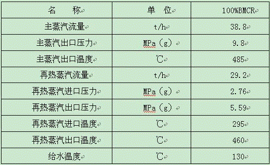
when in use, the flue gas flow is as follows: the garbage is fed and combusted in the fire grate 2 and the incineration hearth 1, the generated high-temperature flue gas flows through the vertical flues 3, 4 and 5, the horizontal flue 6 and the tail flue 7 in sequence and is led out through the tail flue 7, the high-temperature flue gas carries out radiation heat exchange in the vertical flues 3 to 5, and the ash bucket 10 and the economizer ash bucket 12 are used for collecting and discharging the deposited fly ash in the flue gas; the steam-water flow on the superheater side is as follows: the feed water is firstly introduced into an economizer 11 and introduced into a boiler barrel 8 through a connecting pipe, boiler water in the boiler barrel 8 is respectively sent to water cooling walls of vertical flues 3, 4 and 5, a water cooling evaporation screen 13, a high-temperature evaporator 16 and a low-temperature evaporator 22 for radiation or convection heat exchange, saturated steam in the boiler barrel 8 is introduced out through a steam connecting pipe, introduced into a heated pipe surface 15 through a ceiling superheater 9 and then sequentially sent into a low-temperature superheater 20, a medium-temperature superheater 19 and a high-temperature superheater 17, and is introduced out from an outlet of the high-temperature superheater 17 to a high-pressure cylinder of a steam turbine for acting; the steam-water flow at the reheater side is as follows: the reheated steam on the steam turbine side is introduced by the low-temperature reheater 21, flows through the high-temperature reheater 18, is led out from the outlet of the high-temperature reheater 18 and is sent to a low-pressure cylinder of the steam turbine to do work;
the two side walls 14 of the horizontal flue 6 of the utility model adopt steam cooling wrapping walls, which can effectively reduce the superheater area in the flue, make the whole exhaust-heat boiler compact in structure, save space, solve the problems of greatly increased superheater area and difficult arrangement of heating surface caused by the improvement of the parameters of the exhaust-heat furnace, add the water-cooling evaporation screen 13 in the vertical flue 5 in front of the horizontal flue 6, through adjusting the screen number and height of the water-cooling evaporation screen 13, control the convection area through the water-cooling evaporation screen 13, especially the temperature of the smoke at the inlet of the high-temperature superheater 18 is in a reasonable interval, make the high-temperature corrosion controllable, the temperature of the smoke at the inlet of the high-temperature superheater can be adjusted by the water-cooling evaporation screen 13 and the high-temperature evaporator 17 together, the adjusting range is large, can adapt to the refuse fuels with different heat values, and each heating surface and the flow direction of the smoke are, the main steam pressure is 9.8MPa or above, the flexibility of the arrangement of the heating surface of the convection heat exchange area is increased, the layout of the heating surface is compact, the economy is good, the overall thermal efficiency of the waste incineration power plant is improved, and the running stability is ensured;
by adding the primary reheating system of the low-temperature reheater 21 and the high-temperature reheater 18, the heat consumption of a steam turbine can be obviously reduced, the efficiency of a power plant is improved, for example, the temperature of reheated steam is higher accidentally, and accident condition temperature reduction is performed on the reheated steam parameters through the water spray attemperator 23 and the accident water spray attemperator 24, so that the stability of operation is ensured;
if the temperature of the main steam is accidentally higher, the steam parameters can be reduced through the water spraying desuperheaters 25 and 26, so that the running stability is ensured;
the anti-corrosion material layer can ensure that the service life of the tube panel of the high-temperature heating surface is not less than 10 years, and the continuous operation time of a power plant is increased;
example two
The embodiment adopts domestic garbage fuel with a low calorific value of 8370kj/kg, the garbage treatment capacity is 500t/d, and the design parameters of the boiler are as follows:
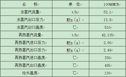
since the design fuel heating value and the main steam parameter are further improved, as shown in fig. 3, the present embodiment is different from the first embodiment in that: 1. the low-temperature evaporator 22 in the first embodiment is eliminated and replaced by a secondary low-temperature superheater 27; 2. the middle-temperature superheater 19 is arranged in front of the high-temperature superheater 17, namely a high-temperature evaporator 16, the middle-temperature superheater 19, the high-temperature superheater 17, a high-temperature reheater 18, a low-temperature superheater 20, a secondary low-temperature superheater 27 and a low-temperature reheater 21 are sequentially arranged in the horizontal flue 6 according to the flow direction of flue gas, two ends of the secondary low-temperature superheater 27 are connected with the low-temperature superheater 20 and a heated pipe surface 15 through steam pipes, namely a boiler barrel 8 is sequentially connected with a ceiling superheater 9, heated pipe surfaces 15 of two steam cooling wrapping walls, the secondary low-temperature superheater 27, the low-temperature superheater 20, the middle-temperature superheater 19 and the; in order to control the wall temperature, the high-temperature superheater 17 and the high-temperature reheater 18 are arranged in a concurrent flow mode with the flow direction of the flue gas; the main steam parameters are improved, the requirement on the water-cooling heating surface is reduced, and the height of the water-cooling evaporation screen 13 can be reduced; for the refuse fuel with slightly high heat value, the temperature of the tail flue gas in the horizontal flue 6 is slightly high, and the secondary low-temperature superheater 27 and the intermediate-temperature superheater 19 are additionally arranged in front of the high-temperature superheater 17, so that the heat efficiency is improved, the steam parameters and the operation stability are improved, and the corrosion rate of the high-temperature level heating surface is controlled within a reasonable interval.
Through the system configuration of the first embodiment and the second embodiment, the waste heat boiler with high-grade parameters can be realized, and the corrosion rate of the high-temperature-grade heating surface is controlled within a reasonable interval.
Claims (7)
1. A high-parameter garbage waste heat boiler comprises an incineration hearth, a fire grate, more than two vertical flues, a horizontal flue, a tail flue and a boiler barrel; water-cooled walls are arranged in the vertical flues; the top of the horizontal flue is provided with a ceiling superheater, and the lower part of the horizontal flue is provided with a plurality of ash hoppers; the coal economizer is arranged in the tail flue and provided with a water supply inlet pipe, the coal economizer is connected with the boiler barrel through a connecting pipe, and the boiler barrel is connected with each water-cooled wall; the method is characterized in that: a water-cooling evaporation screen is arranged in at least one vertical flue in front of the horizontal flue; the two side walls of the horizontal flue are steam-cooled wrap walls with heated pipe surfaces arranged on the inner sides; a high-temperature evaporator is arranged in front of the horizontal flue, and a high-temperature superheater, a medium-temperature superheater and a low-temperature superheater are arranged behind the high-temperature evaporator; the boiler barrel, the water-cooling evaporation screen and the high-temperature evaporator are connected with a water feeding pipe through a water discharging pipe; the boiler barrel is sequentially connected with a ceiling superheater, a heated pipe surface of a steam cooling wrapping wall, a low-temperature superheater, a medium-temperature superheater and a high-temperature superheater through a steam connecting pipe.
2. The high parameter waste heat boiler of claim 1, characterized in that: a low-temperature evaporator is also arranged in the horizontal flue, and the boiler barrel is connected with the low-temperature evaporator through a sewer pipe and a water supply pipe; the high-temperature evaporator, the high-temperature superheater, the medium-temperature superheater, the low-temperature superheater and the low-temperature evaporator are sequentially arranged in the horizontal flue according to the flow direction of flue gas.
3. The high parameter waste heat boiler of claim 2, characterized in that: a high-temperature reheater is arranged between the high-temperature superheater and the medium-temperature superheater, a low-temperature reheater is arranged behind the low-temperature superheater, and the high-temperature reheater is connected with the low-temperature reheater through a pipeline.
4. The high parameter waste heat boiler of claim 1, characterized in that: a secondary low-temperature superheater is also arranged in the horizontal flue; the high-temperature evaporator, the medium-temperature superheater, the high-temperature superheater, the low-temperature superheater and the secondary low-temperature superheater are sequentially arranged in the horizontal flue according to the flow direction of flue gas, and two ends of the secondary low-temperature superheater are connected with the low-temperature superheater and a heated pipe surface through steam connecting pipes.
5. The high parameter waste heat boiler of claim 4, characterized in that: a high-temperature reheater is arranged between the high-temperature superheater and the low-temperature superheater, a low-temperature reheater is arranged behind the secondary low-temperature superheater, and the high-temperature reheater is connected with the low-temperature reheater through a pipeline.
6. The high parameter waste heat boiler of claim 1, 2 or 4, wherein: and corrosion-resistant material layers are covered outside the tubes of the high-temperature superheater and the medium-temperature superheater.
7. The high parameter waste heat boiler of claim 3 or 5, wherein: and corrosion-resistant material layers are covered outside the tubes of the high-temperature superheater, the high-temperature reheater and the medium-temperature superheater.
Priority Applications (1)
| Application Number | Priority Date | Filing Date | Title |
|---|---|---|---|
| CN201922438963.0U CN211667829U (en) | 2019-12-30 | 2019-12-30 | High-parameter garbage waste heat boiler |
Applications Claiming Priority (1)
| Application Number | Priority Date | Filing Date | Title |
|---|---|---|---|
| CN201922438963.0U CN211667829U (en) | 2019-12-30 | 2019-12-30 | High-parameter garbage waste heat boiler |
Publications (1)
| Publication Number | Publication Date |
|---|---|
| CN211667829U true CN211667829U (en) | 2020-10-13 |
Family
ID=72737435
Family Applications (1)
| Application Number | Title | Priority Date | Filing Date |
|---|---|---|---|
| CN201922438963.0U Active CN211667829U (en) | 2019-12-30 | 2019-12-30 | High-parameter garbage waste heat boiler |
Country Status (1)
| Country | Link |
|---|---|
| CN (1) | CN211667829U (en) |
-
2019
- 2019-12-30 CN CN201922438963.0U patent/CN211667829U/en active Active
Similar Documents
| Publication | Publication Date | Title |
|---|---|---|
| CN201310896Y (en) | Biomass incinerator of high temperature and high pressure circulating fluidized bed | |
| CN103591575A (en) | Supercritical circulating fluidized bed boiler of 350MW and vapor circulation method | |
| CN2903708Y (en) | Straw direct burning boiler | |
| CN209978041U (en) | High-temperature high-pressure waste incineration boiler | |
| CN111520696A (en) | Exhaust-heat boiler arrangement structure burning high-calorific-value garbage | |
| CN111059546A (en) | High-parameter garbage waste heat boiler | |
| CN111550758A (en) | High-capacity high-parameter waste incineration waste heat boiler | |
| CN107559804A (en) | A kind of garbage burning boiler superheater system | |
| CN111795379A (en) | Circulating fluidized bed boiler for burning biomass | |
| CN207378803U (en) | A kind of garbage burning boiler superheater system | |
| CN211667829U (en) | High-parameter garbage waste heat boiler | |
| CN203656913U (en) | 350MW supercritical circulating fluidized bed boiler | |
| CN203203010U (en) | Boiler for yellow phosphorus tail gas combustion | |
| CN205825033U (en) | High parameter garbage burning boiler with reheating | |
| CN214223090U (en) | Circulating fluidized bed boiler using solid waste | |
| CN209763080U (en) | High-temperature high-pressure waste incineration pi-type boiler | |
| CN111720836B (en) | Super high pressure grate waste incineration boiler | |
| CN210241580U (en) | High-parameter grate waste incineration boiler | |
| CN210035461U (en) | Garbage reheating boiler | |
| CN111207373A (en) | Waste incineration waste heat boiler system with flue gas reheating function | |
| CN110793012A (en) | Pure-burning biomass environment-friendly circulating fluidized bed boiler water vapor system | |
| CN218721493U (en) | Novel waste incineration boiler | |
| CN105782989A (en) | Intake method of garbage incineration boiler hearth and garbage incineration boiler equipment thereof | |
| CN209763081U (en) | High-temperature high-pressure vertical boiler for waste incineration | |
| CN209978040U (en) | High-temperature high-pressure garbage incineration horizontal boiler |
Legal Events
| Date | Code | Title | Description |
|---|---|---|---|
| GR01 | Patent grant | ||
| GR01 | Patent grant |