CN211658144U - Fixing device of electrocardiograph wire - Google Patents
Fixing device of electrocardiograph wire Download PDFInfo
- Publication number
- CN211658144U CN211658144U CN201922049559.4U CN201922049559U CN211658144U CN 211658144 U CN211658144 U CN 211658144U CN 201922049559 U CN201922049559 U CN 201922049559U CN 211658144 U CN211658144 U CN 211658144U
- Authority
- CN
- China
- Prior art keywords
- wire
- electrocardiograph
- telescopic
- tube
- fixing device
- Prior art date
- Legal status (The legal status is an assumption and is not a legal conclusion. Google has not performed a legal analysis and makes no representation as to the accuracy of the status listed.)
- Expired - Fee Related
Links
Images


Landscapes
- Measurement And Recording Of Electrical Phenomena And Electrical Characteristics Of The Living Body (AREA)
Abstract
本实用新型实施例公开了一种心电图机导线的固定装置,包括伸缩束线管和分线器,所述伸缩束线管的下端与心电图机侧壁的出线口连接,若干根心电图机导线穿设在所述伸缩束线管内,且所述伸缩束线管的上端与所述分线器连接;所述分线器包括与所述伸缩束线管连接排线条以及连接在所述排线条下端的调节板,所述排线条横向开设有若干个穿线孔,所述心电图机导线一一对应的穿设在所述穿线孔内,且所述心电图机导线上活动设置有固线夹,所述调节板上开设有与所述固线夹一一对应的滑道;本实用新型实施例不仅可实现众多导线的梳理工作,还可以所有的导线除末端贴片外均不与人体直接接触,避免导线贴设造成的人体瘙痒等不适。
The embodiment of the utility model discloses a fixing device for an electrocardiograph wire, which comprises a telescopic wire harness and a wire splitter. It is arranged in the telescopic wire harness, and the upper end of the telescopic wire harness is connected to the wire splitter; the wire splitter includes a flat wire connected to the telescopic wire harness and a lower end of the flat wire. There are several threading holes horizontally opened on the row line, and the electrocardiograph lead wires are threaded in the threading holes in a one-to-one correspondence, and the electrocardiograph lead wires are movably provided with fixed wire clips. The adjusting plate is provided with slideways corresponding to the wire fixing clips one-to-one; the embodiment of the present utility model can not only realize the combing work of many wires, but also all wires except for the end patch are not in direct contact with the human body, avoiding the need for Human body itching and other discomfort caused by wire sticking.
Description
技术领域technical field
本实用新型实施例涉及医疗辅助器械领域,具体涉及一种心电图机导线的固定装置。The embodiment of the utility model relates to the field of medical aids, in particular to a fixing device for an electrocardiograph lead.
背景技术Background technique
心电图机能将心脏活动时心肌激动产生的生物电信号(心电信号)自动记录下来,为临床诊断和科研常用的医疗电子仪器。在心电图机使用过程中,一般是将病人安放在病床上,然后配合心电图检测仪、心电图导联线使用,目前的心电图检测仪一般都连接有至少12条导联线,数量较多,且考虑到人的身高和体形不同,导联线都比较长,在使用过程中导联线经常缠绕在一起,需要花大量的时间逐根进行理顺,操作麻烦和对抢救工作带来不便,还容易造成导联线的损坏,效率非常低。因此现有技术提供了各种用于心电图机导线的理线装置对心电图机导线进行梳理,避免导线打结。The electrocardiograph can automatically record the bioelectric signal (ECG signal) generated by the cardiac activity when the heart is active, and is a medical electronic instrument commonly used in clinical diagnosis and scientific research. In the process of using the ECG machine, the patient is generally placed on the bed, and then used with the ECG detector and the ECG lead wires. The current ECG detector is generally connected with at least 12 lead wires, and the number is large, and consideration should be given to it. Depending on the person's height and body shape, the lead wires are relatively long, and the lead wires are often entangled during use. It takes a lot of time to straighten them out one by one, which is troublesome to operate and brings inconvenience to the rescue work. Causes damage to the lead wire, and the efficiency is very low. Therefore, the prior art provides various wire-arranging devices for the lead of the electrocardiograph to comb the lead of the electrocardiograph to avoid knotting of the lead.
例如,申请号为201520064003.1,专利名称为一种简易的扣合式心电图机导线理线器,在胸导联模块上扣合板和肢体导联模块上扣合板之间、胸导联模块下扣合板和肢体导联模块下扣合板之间分别设有用于相互配合扣合的扣合槽和扣合棱,胸导联模块上扣合板和胸导联模块下扣合板之间、肢体导联模块上扣合板和肢体导联模块下扣合板之间设有用于配合形成导线孔的上半圆槽和下半圆槽,该装置体积小易整理,使用方便,固定牢靠,适用于任何类型心电图机。但是该装置仅能实现对导线的固定和梳理从而避免导线缠绕,而在对患者进行心电图检查时,由于心电图机导线数量众多,将导线端部的电极片贴设在测试部位后,剩余过长的导线则与人体的肌肤直接接触,极易造成患者的不适。For example, the application number is 201520064003.1, and the patent name is a simple snap-fit electrocardiograph lead wire organizer. The lower buckling plates of the limb lead module are respectively provided with buckling grooves and buckling edges for mutual cooperation and buckling, the upper buckling plate of the chest lead module and the lower buckling plate of the chest lead module, and the upper buckling plate of the limb lead module are buckled. There are upper semicircular grooves and lower semicircular grooves between the plywood and the lower clasp plate of the limb lead module, which are used to form a wire hole. However, this device can only fix and comb the lead to avoid the lead from entanglement. When performing an ECG examination on a patient, due to the large number of electrocardiograph leads, the electrode at the end of the lead is attached to the test site, and the remaining length is too long. The lead wire is in direct contact with the skin of the human body, which can easily cause discomfort to the patient.
实用新型内容Utility model content
为此,本实用新型实施例提供一种心电图机导线的固定装置,以解决当前心电图机对人体进行测试检查时,众多数量的导线直接与人体裸露肌肤接触造成的肌肤不适的问题。To this end, the embodiment of the present invention provides a fixing device for electrocardiograph wires, so as to solve the problem of skin discomfort caused by a large number of wires directly contacting the bare skin of the human body when the current electrocardiograph machine tests and inspects the human body.
为了实现上述目的,本实用新型的实施方式提供如下技术方案:In order to achieve the above purpose, the embodiments of the present utility model provide the following technical solutions:
一种心电图机导线的固定装置,包括伸缩束线管和分线器,所述伸缩束线管的下端与心电图机侧壁的出线口连接,若干根心电图机导线穿设在所述伸缩束线管内,且所述伸缩束线管的上端与所述分线器连接;An electrocardiograph wire fixing device, comprising a telescopic wire harness and a wire splitter, the lower end of the telescopic wire harness is connected to a wire outlet on the side wall of the electrocardiograph, and a plurality of electrocardiograph wires are passed through the telescopic wire harness inside the tube, and the upper end of the telescopic wire harness is connected to the wire splitter;
所述分线器包括与所述伸缩束线管连接排线条以及连接在所述排线条下端的调节板,所述排线条横向开设有若干个穿线孔,所述心电图机导线一一对应的穿设在所述穿线孔内,且所述心电图机导线上活动设置有固线夹,所述调节板上开设有与所述固线夹一一对应的滑道。The wire splitter includes a flat wire connected to the telescopic wire harness and an adjustment plate connected to the lower end of the flat wire. It is arranged in the threading hole, and the wire of the electrocardiograph is movably provided with a fixing clip, and the adjusting plate is provided with a slideway corresponding to the fixing clip one-to-one.
作为本实用新型的一种优选方案,所述伸缩束线管包括与所述排线条连接的上接管、与所述心电图机连接的下接管以及用于调节上接管和下接管相对距离的调节管,所述调节管的下端与所述下接管转动连接,所述调节管的上端通过螺纹与所述上接管固定连接。As a preferred solution of the present invention, the telescopic cable harness includes an upper tube connected to the flat cable, a lower tube connected to the electrocardiograph, and an adjustment tube for adjusting the relative distance between the upper tube and the lower tube , the lower end of the adjusting pipe is rotatably connected with the lower pipe, and the upper end of the adjusting pipe is fixedly connected with the upper pipe through threads.
作为本实用新型的一种优选方案,所述下接管的上端管壁上开设有环状凹槽,所述调节管的下端设置有用于卡装在所述环状凹槽内的环圈。As a preferred solution of the present invention, an annular groove is formed on the pipe wall of the upper end of the lower nozzle, and a ring for clamping in the annular groove is arranged at the lower end of the adjusting pipe.
作为本实用新型的一种优选方案,所述分线器与所述伸缩束线管之间通过转接套连接,所述转接套由缩口段与扩口段一体化连接组成,所述缩口段与所述伸缩束线管的上端连接,所述扩口段包覆在所述分线器的侧边缘。As a preferred solution of the present invention, the splitter and the telescopic wire harness are connected by an adapter sleeve, and the adapter sleeve is composed of an integrated connection of a constricted section and a flared section. The necking section is connected with the upper end of the telescopic wire harness, and the flared section covers the side edge of the wire splitter.
作为本实用新型的一种优选方案,所述固线夹的底部设置有磁铁片,所述滑道的底部设置有与磁铁片互相吸引的吸附层。As a preferred solution of the present invention, the bottom of the wire fixing clip is provided with a magnet sheet, and the bottom of the slideway is provided with an adsorption layer that attracts the magnet sheet to each other.
本实用新型的实施方式具有如下优点:The embodiment of the present invention has the following advantages:
本实用新型实施例将心电图机的导线首先沿伸缩束线管穿设,经过分线器时,每一根导线穿设在对应的穿线孔内,实现众多导线的梳理工作,避免其互相缠绕,同时当导线末端的电极贴片贴设在测试部位后,可利用伸缩束线管的伸缩功能一次性粗调所有导线的高度,使其垂悬于空中不与人体肌肤直接接触,对于部分导线与脚踝等部位连接,导线较长,在粗调过后可通过将固线夹沿调节板上的滑道向上滑行,依次调节,直至所有的导线除末端贴片外均不与人体直接接触,避免导线贴设造成的人体瘙痒等不适。In the embodiment of the utility model, the wires of the electrocardiograph are firstly threaded along the telescopic wire harness, and when passing through the wire splitter, each wire is threaded into the corresponding threading hole, so as to realize the combing work of many wires and avoid intertwining. At the same time, when the electrode patch at the end of the wire is attached to the test site, the telescopic function of the telescopic cable duct can be used to roughly adjust the height of all wires at one time, so that it hangs in the air and does not directly contact human skin. The ankles and other parts are connected, and the wires are long. After the rough adjustment, you can slide the fixing wire clip upward along the slideway on the adjustment board, and adjust in turn until all the wires are not in direct contact with the human body except the end patch, so as to avoid the wire Itching and other discomforts caused by the sticker.
附图说明Description of drawings
为了更清楚地说明本实用新型的实施方式或现有技术中的技术方案,下面将对实施方式或现有技术描述中所需要使用的附图作简单地介绍。显而易见地,下面描述中的附图仅仅是示例性的,对于本领域普通技术人员来讲,在不付出创造性劳动的前提下,还可以根据提供的附图引伸获得其它的实施附图。In order to more clearly illustrate the embodiments of the present invention or the technical solutions in the prior art, the following briefly introduces the accompanying drawings that are required to be used in the description of the embodiments or the prior art. Obviously, the drawings in the following description are only exemplary, and for those of ordinary skill in the art, other implementation drawings can also be obtained according to the extension of the drawings provided without creative efforts.
本说明书所绘示的结构、比例、大小等,均仅用以配合说明书所揭示的内容,以供熟悉此技术的人士了解与阅读,并非用以限定本实用新型可实施的限定条件,故不具技术上的实质意义,任何结构的修饰、比例关系的改变或大小的调整,在不影响本实用新型所能产生的功效及所能达成的目的下,均应仍落在本实用新型所揭示的技术内容得能涵盖的范围内。The structures, proportions, sizes, etc. shown in this specification are only used to cooperate with the contents disclosed in the specification, so as to be understood and read by those who are familiar with the technology, and are not used to limit the conditions that the present invention can be implemented. The technical substantive significance, the modification of any structure, the change of the proportional relationship or the adjustment of the size, without affecting the effect that the utility model can produce and the purpose that can be achieved, should still fall within the scope disclosed in the present utility model. The technical content must be within the scope of coverage.
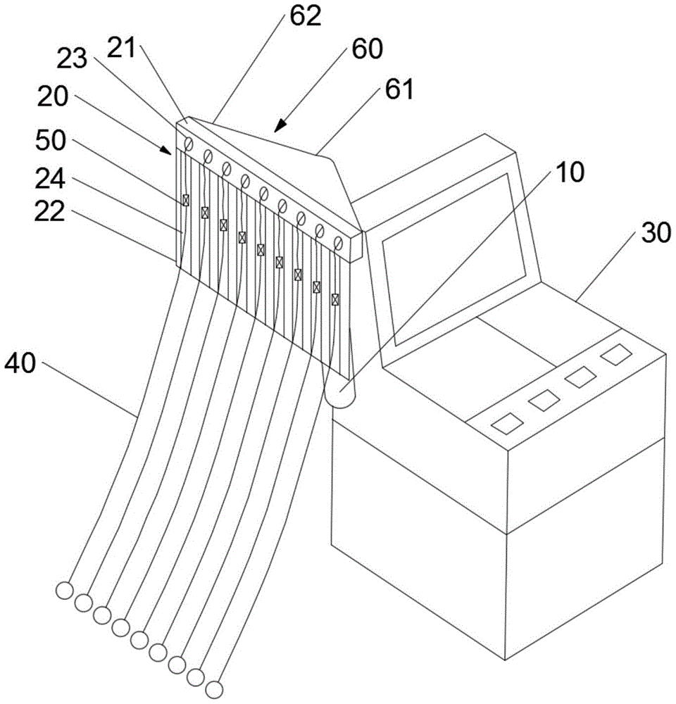
图1为本实用新型实施例提供的心电图机导线的固定装置的整体结构示意图;1 is a schematic diagram of the overall structure of a fixing device for an electrocardiograph lead according to an embodiment of the present invention;
图2为图1所示心电图机导线的固定装置中伸缩束线管的爆炸图。FIG. 2 is an exploded view of the telescopic wire harness in the fixing device of the electrocardiograph wire shown in FIG. 1 .
图中:In the picture:
10-伸缩束线管;20-分线器;30-心电图机;40-心电图机导线;50-固线夹;60-转接套;10- telescopic wire harness; 20- splitter; 30- ECG machine; 40- ECG machine lead wire; 50- fixed wire clip; 60- transfer sleeve;
11-上接管;12-下接管;11-take over; 12-take over;
21-排线条;22-调节板;23-穿线孔;24-滑道;21-line; 22-adjustment plate; 23-thread hole; 24-slide;
61-缩口段;62-扩口段;61 - necked section; 62 - flared section;
121-环状凹槽;131-环圈。121-annular groove; 131-ring.
具体实施方式Detailed ways
以下由特定的具体实施例说明本实用新型的实施方式,熟悉此技术的人士可由本说明书所揭露的内容轻易地了解本实用新型的其他优点及功效,显然,所描述的实施例是本实用新型一部分实施例,而不是全部的实施例。基于本实用新型中的实施例,本领域普通技术人员在没有做出创造性劳动前提下所获得的所有其他实施例,都属于本实用新型保护的范围。The embodiments of the present invention will be described below by specific specific embodiments. Those who are familiar with the technology can easily understand other advantages and effects of the present invention from the contents disclosed in this specification. Obviously, the described embodiments are of the present invention. Some examples, but not all examples. Based on the embodiments of the present invention, all other embodiments obtained by those of ordinary skill in the art without creative work fall within the protection scope of the present invention.
如图1所示,本实用新型提供了一种心电图机导线的固定装置,包括伸缩束线管10和分线器20,所述伸缩束线管10的下端与心电图机30侧壁的出线口连接,若干根心电图机导线40穿设在所述伸缩束线管10内,且所述伸缩束线管10的上端与所述分线器20连接;As shown in FIG. 1 , the present invention provides a fixing device for electrocardiograph wires, including a
所述分线器20包括与所述伸缩束线管10连接排线条21以及连接在所述排线条21下端的调节板22,所述排线条21横向开设有若干个穿线孔23,所述心电图机导线40一一对应的穿设在所述穿线孔23内,且所述心电图机导线40上活动设置有固线夹50,所述调节板22上开设有与所述固线夹50一一对应的滑道24。The cable splitter 20 includes a
区别于传统的心电图机导线的固定装置仅能实现众多导线的理线功能,避免互相缠绕,本实用新型实施例的特征之处在于,还能对心电图机测试过程中导线的高度进行调节,避免众多导线均贴设在人体的表面造成患者肌肤的瘙痒等不适,从而影响测试结果。Different from the traditional electrocardiograph wire fixing device, which can only realize the wire management function of many wires and avoid mutual entanglement, the embodiment of the present utility model is characterized in that it can also adjust the height of the wires during the electrocardiograph test process, avoiding the need for Many wires are attached to the surface of the human body, causing discomfort such as itching of the patient's skin, thereby affecting the test results.
具体地,本利用装置对心电图机导线40进行固定的过程为:首先众多的心电图机导线40沿伸缩束线管10向上穿出,然后经过分线器20,每一根心电图机导线40一一对应的穿设在排线条上21的穿线孔23内,实现众多心电图机导线40的分离和排布,避免其互相缠绕。Specifically, the process of using the device to fix the
在对患者进行心电图测试检查时,首先将心电图机导线40端部的电极贴片依次与人体待测试部位连接,然后利用伸缩束线管10的伸缩功能一次性调节所有心电图机导线40的高度,使心电图机导线40垂悬于空中,对应个别用于脚踝等测试部位的导线,由于其长度较长,因此,可单独调节其垂悬高度,将心电图机导线40下端的固线夹50沿调节板22上的滑道24向上移动直至所有的心电图机导线40除电极贴片以外的地方均不与人体肌肤接触,避免造成的不适感。When performing an electrocardiogram test on a patient, first connect the electrode patches at the end of the
如图2所示,所述伸缩束线管10包括与所述排线条21连接的上接管11、与所述心电图机30连接的下接管12以及用于调节上接管11和下接管12相对距离的调节管13,所述调节管13的下端与所述下接管12转动连接,所述调节管13的上端通过螺纹与所述上接管11固定连接。As shown in FIG. 2 , the
进一步地,所述下接管12的上端管壁上开设有环状凹槽121,所述调节管13的下端设置有用于卡装在所述环状凹槽121内的环圈131。Further, an
伸缩束线管10的调节过程为,转动调节管13,由于调节管13与下接管 12为卡槽嵌装的转动连接形式,因此调节管13在转动时,下接管12不随其一同转动,利用调节管13的顺时针或者逆时针转动实现沿上接管11的旋上或者旋下,从而改变整个伸缩束线管10的长度。The adjustment process of the
在本实用新型中所述分线器20与所述伸缩束线管10的连接具体是通过转接套60连接,所述转接套60由缩口段61与扩口段62一体化连接组成,所述缩口段61与所述伸缩束线管10的上端连接,所述扩口段62包覆在所述分线器20的侧边缘,In the present invention, the connection between the splitter 20 and the
而固线夹50沿滑道24滑动且可以止滑的具体实现是通过在所述固线夹 50的底部设置有磁铁片,所述滑道24的底部设置有与磁铁片互相吸引的吸附层,这里的吸附层可以是铁片等材质,使固线夹50可以固定在滑道24的任意位置。The specific realization that the
虽然,上文中已经用一般性说明及具体实施例对本实用新型作了详尽的描述,但在本实用新型基础上,可以对之作一些修改或改进,这对本领域技术人员而言是显而易见的。因此,在不偏离本实用新型精神的基础上所做的这些修改或改进,均属于本实用新型要求保护的范围。Although the present utility model has been described in detail above with general description and specific embodiments, some modifications or improvements can be made on the basis of the present utility model, which is obvious to those skilled in the art. Therefore, these modifications or improvements made on the basis of not departing from the spirit of the present invention belong to the protection scope of the present invention.
Claims (5)
Priority Applications (1)
| Application Number | Priority Date | Filing Date | Title |
|---|---|---|---|
| CN201922049559.4U CN211658144U (en) | 2019-11-25 | 2019-11-25 | Fixing device of electrocardiograph wire |
Applications Claiming Priority (1)
| Application Number | Priority Date | Filing Date | Title |
|---|---|---|---|
| CN201922049559.4U CN211658144U (en) | 2019-11-25 | 2019-11-25 | Fixing device of electrocardiograph wire |
Publications (1)
| Publication Number | Publication Date |
|---|---|
| CN211658144U true CN211658144U (en) | 2020-10-13 |
Family
ID=72732535
Family Applications (1)
| Application Number | Title | Priority Date | Filing Date |
|---|---|---|---|
| CN201922049559.4U Expired - Fee Related CN211658144U (en) | 2019-11-25 | 2019-11-25 | Fixing device of electrocardiograph wire |
Country Status (1)
| Country | Link |
|---|---|
| CN (1) | CN211658144U (en) |
Cited By (1)
| Publication number | Priority date | Publication date | Assignee | Title |
|---|---|---|---|---|
| CN115337019A (en) * | 2022-09-19 | 2022-11-15 | 河南省第二人民医院 | Anti-interference electrocardio inspection device |
-
2019
- 2019-11-25 CN CN201922049559.4U patent/CN211658144U/en not_active Expired - Fee Related
Cited By (1)
| Publication number | Priority date | Publication date | Assignee | Title |
|---|---|---|---|---|
| CN115337019A (en) * | 2022-09-19 | 2022-11-15 | 河南省第二人民医院 | Anti-interference electrocardio inspection device |
Similar Documents
| Publication | Publication Date | Title |
|---|---|---|
| CN205411177U (en) | Electrocardioelectrode and contain electrocardio monitoring devices of this electrode | |
| CN204207742U (en) | Air suction type electrocardio vacuum harvesting apparatus | |
| CN209574684U (en) | A kind of wireless electrocardiograph monitoring device | |
| TWM579010U (en) | Flexible ECG detection device | |
| CN205924012U (en) | Electrocardiograph leads line and parts device | |
| CN116763320A (en) | A device for retracting and releasing lead wires of an electrocardiogram monitor | |
| CN209252863U (en) | A portable ECG electrode sheet | |
| CN209789846U (en) | Electrocardiogram detection stabilizing device | |
| CN209770361U (en) | ECG monitor with automatic retraction of lead wire | |
| CN209360680U (en) | A kind of blood pressure alarm device for hypertensive patient's nursing | |
| CN217793085U (en) | Electrocardiogram wire bunching device and wire bunching device | |
| CN221490002U (en) | Dynamic electrocardiogram device | |
| CN216602851U (en) | Wire binding device of sleep monitor | |
| CN222466920U (en) | Lead wire fixer of bedside electrocardiograph | |
| CN209172299U (en) | A kind of ECG monitor conducting wire storage device | |
| CN207721809U (en) | A kind of fixator for electrocardiograph probe | |
| CN202981995U (en) | Anti-twisting device for electrocardiogram machine probe wiring harness | |
| CN217390723U (en) | A storage device for ECG monitoring lead wires | |
| CN203898297U (en) | Anti-wire-winding component and twelve-lead electrocardiograph wire anti-winding device | |
| CN209966372U (en) | ECG lead harness wire management device | |
| CN214318023U (en) | Wearable electrocardio monitoring devices | |
| CN206167051U (en) | Line protective sheath leads | |
| CN215384114U (en) | Wire harness fixing device of electrocardiogram lead wire | |
| CN210697623U (en) | Electrocardiogram wire clamp | |
| CN206102646U (en) | A five lead for ECG monitor |
Legal Events
| Date | Code | Title | Description |
|---|---|---|---|
| GR01 | Patent grant | ||
| GR01 | Patent grant | ||
| CF01 | Termination of patent right due to non-payment of annual fee |
Granted publication date: 20201013 Termination date: 20211125 |
|
| CF01 | Termination of patent right due to non-payment of annual fee |