CN211656057U - Photovoltaic module with adjustable installation angle - Google Patents
Photovoltaic module with adjustable installation angle Download PDFInfo
- Publication number
- CN211656057U CN211656057U CN202020040907.1U CN202020040907U CN211656057U CN 211656057 U CN211656057 U CN 211656057U CN 202020040907 U CN202020040907 U CN 202020040907U CN 211656057 U CN211656057 U CN 211656057U
- Authority
- CN
- China
- Prior art keywords
- installation
- hole
- spring
- bracket
- fixing
- Prior art date
- Legal status (The legal status is an assumption and is not a legal conclusion. Google has not performed a legal analysis and makes no representation as to the accuracy of the status listed.)
- Expired - Fee Related
Links
- 238000009434 installation Methods 0.000 title claims abstract description 44
- 238000003466 welding Methods 0.000 claims description 3
- 238000010586 diagram Methods 0.000 description 3
- 238000005286 illumination Methods 0.000 description 3
- 230000009286 beneficial effect Effects 0.000 description 1
- 238000000034 method Methods 0.000 description 1
- 238000004806 packaging method and process Methods 0.000 description 1
- 238000010248 power generation Methods 0.000 description 1
Images

Classifications
-
- Y—GENERAL TAGGING OF NEW TECHNOLOGICAL DEVELOPMENTS; GENERAL TAGGING OF CROSS-SECTIONAL TECHNOLOGIES SPANNING OVER SEVERAL SECTIONS OF THE IPC; TECHNICAL SUBJECTS COVERED BY FORMER USPC CROSS-REFERENCE ART COLLECTIONS [XRACs] AND DIGESTS
- Y02—TECHNOLOGIES OR APPLICATIONS FOR MITIGATION OR ADAPTATION AGAINST CLIMATE CHANGE
- Y02E—REDUCTION OF GREENHOUSE GAS [GHG] EMISSIONS, RELATED TO ENERGY GENERATION, TRANSMISSION OR DISTRIBUTION
- Y02E10/00—Energy generation through renewable energy sources
- Y02E10/50—Photovoltaic [PV] energy
Landscapes
- Photovoltaic Devices (AREA)
Abstract
本实用新型公开了安装角度可调的光伏模组,包括固定台,固定台的顶面安装有支架,支架的顶端成型有安装槽,安装槽内安装有固定块,固定块的下端为半圆形,固定块的顶面安装有用于安装太阳能光伏板的支撑板,固定块内穿有转杆,转杆的左右两端与安装槽内壁转动配合,固定块的左侧成型有多个固定孔,支架的左侧成型有通孔,通孔与安装槽相通,支架的左侧连接有安装圆环,安装圆环与通孔同心,安装圆环内插有插销,插销的左侧连接有螺帽,插销的外套有弹簧,弹簧的右端与安装圆环的左侧连接,弹簧的左端与螺帽的右侧连接,插销通过弹簧的弹力插接在某一个固定孔内。
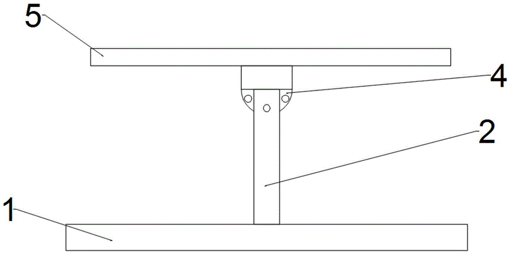
The utility model discloses a photovoltaic module with an adjustable installation angle, comprising a fixing table, a bracket is installed on the top surface of the fixing table, an installation groove is formed at the top of the bracket, a fixing block is installed in the installation groove, and the lower end of the fixing block is a semicircle The top surface of the fixed block is equipped with a support plate for installing the solar photovoltaic panel. The fixed block is penetrated with a rotating rod. The left and right ends of the rotating rod are rotated and matched with the inner wall of the installation groove. The left side of the fixed block is formed with a plurality of fixing holes. , a through hole is formed on the left side of the bracket, the through hole is connected with the installation groove, the left side of the bracket is connected with a mounting ring, the mounting ring is concentric with the through hole, a bolt is inserted in the installation ring, and the left side of the bolt is connected with a screw The cover of the cap and the bolt has a spring, the right end of the spring is connected with the left side of the installation ring, the left end of the spring is connected with the right side of the nut, and the bolt is inserted into a certain fixing hole through the elastic force of the spring.
Description
技术领域technical field
本实用新型涉及光伏模组安装领域,尤其是涉及安装角度可调的光伏模组。The utility model relates to the field of photovoltaic module installation, in particular to a photovoltaic module with an adjustable installation angle.
背景技术Background technique
光伏模组又称作太阳能模组、太阳能板,是将许多光伏电池互连并包装的产物,如此互连的而达到的发电规模可提供商业大楼、住宅使用。Photovoltaic modules, also known as solar modules and solar panels, are the product of interconnecting and packaging many photovoltaic cells. The power generation scale achieved by such interconnection can be used in commercial buildings and residences.
目前现有的光伏模组的没有设置可调节结构,太阳能光伏板是固定安装在支架上的,安装的时候根据当时光照的角度确定太阳能光伏板的角度。但是太阳的光照角度会随着季节的变化而变化,那么这种已经固定的太阳能光伏板要么不能转动;要么就是转动结构比较复杂,为了适应光照角度的变化,其仰角调节费时且费力。At present, the existing photovoltaic modules are not provided with an adjustable structure, and the solar photovoltaic panels are fixedly installed on the brackets, and the angle of the solar photovoltaic panels is determined according to the angle of illumination at that time during installation. However, the illumination angle of the sun will change with the change of seasons, so the fixed solar photovoltaic panel either cannot be rotated; or the rotation structure is complicated. In order to adapt to the change of illumination angle, the adjustment of the elevation angle is time-consuming and laborious.
实用新型内容Utility model content
本实用新型为克服上述情况不足,旨在提供一种能解决上述问题的技术方案。In order to overcome the above-mentioned shortcomings, the present invention aims to provide a technical solution that can solve the above-mentioned problems.
安装角度可调的光伏模组,包括固定台,固定台的顶面安装有支架,支架的顶端成型有安装槽,安装槽内安装有固定块,固定块的下端为半圆形,固定块的顶面安装有用于安装太阳能光伏板的支撑板,固定块内穿有转杆,转杆的左右两端与安装槽内壁转动配合,固定块的左侧成型有多个固定孔,支架的左侧成型有通孔,通孔与安装槽相通,支架的左侧连接有安装圆环,安装圆环与通孔同心,安装圆环内插有插销,插销的左侧连接有螺帽,插销的外套有弹簧,弹簧的右端与安装圆环的左侧连接,弹簧的左端与螺帽的右侧连接,插销通过弹簧的弹力插接在某一个固定孔内。The photovoltaic module with adjustable installation angle includes a fixing table, a bracket is installed on the top surface of the fixing table, a mounting groove is formed at the top of the bracket, a fixing block is installed in the installation groove, the lower end of the fixing block is semicircular, and the A support plate for installing solar photovoltaic panels is installed on the top surface. A rotating rod is penetrated in the fixed block. The left and right ends of the rotating rod are rotated and matched with the inner wall of the installation groove. The left side of the fixed block is formed with a plurality of fixed holes. A through hole is formed, and the through hole communicates with the installation groove. The left side of the bracket is connected with a mounting ring, which is concentric with the through hole. There is a spring, the right end of the spring is connected with the left side of the installation ring, the left end of the spring is connected with the right side of the nut, and the pin is inserted into a certain fixing hole by the elastic force of the spring.
作为本实用新型进一步的方案:安装圆环的左侧成型有第一凸块,螺帽的右侧成型有第二凸块,弹簧的前端与第二凸块卡接,弹簧的后端与第一凸块卡接。As a further solution of the present invention: the left side of the installation ring is formed with a first bump, the right side of the nut is formed with a second bump, the front end of the spring is clamped with the second bump, and the rear end of the spring is connected with the second bump. A bump is snapped.
作为本实用新型进一步的方案:安装槽内壁成型有安装孔,转杆设置在安装孔内,转杆的外壁与安装孔的内壁转动配合。As a further solution of the present invention, the inner wall of the installation groove is formed with an installation hole, the rotating rod is arranged in the installation hole, and the outer wall of the rotating rod is rotatably matched with the inner wall of the installation hole.
作为本实用新型进一步的方案:安装圆环通过焊接的方式安装在支架左侧。As a further solution of the present invention, the mounting ring is mounted on the left side of the bracket by welding.
与现有技术相比,本实用新型的有益效果是:通过增加了可调节结构,工作人员可以通过拉动插销来调节太阳能光伏板的角度,结构简单,增加设备实用性。Compared with the prior art, the beneficial effect of the utility model is: by adding an adjustable structure, the staff can adjust the angle of the solar photovoltaic panel by pulling the latch, the structure is simple, and the practicability of the equipment is increased.
本实用新型的附加方面和优点将在下面的描述中部分给出,部分将从下面的描述中变得明显,或通过本实用新型的实践了解到。Additional aspects and advantages of the invention will be set forth, in part, from the following description, and in part will be apparent from the following description, or learned by practice of the invention.
附图说明Description of drawings
为了更清楚地说明本实用新型实施例或现有技术中的技术方案,下面将对实施例或现有技术描述中所需要使用的附图作简单地介绍,显而易见地,下面描述中的附图仅仅是本实用新型的一些实施例,对于本领域普通技术人员来讲,在不付出创造性劳动性的前提下,还可以根据这些附图获得其他的附图。In order to more clearly illustrate the embodiments of the present utility model or the technical solutions in the prior art, the following briefly introduces the accompanying drawings that need to be used in the description of the embodiments or the prior art. Obviously, the accompanying drawings in the following description These are just some embodiments of the present invention, and for those of ordinary skill in the art, other drawings can also be obtained from these drawings without any creative effort.
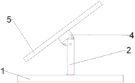
图1是本实用新型结构示意图。Figure 1 is a schematic structural diagram of the present invention.
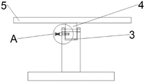
图2是本实用新型的固定块结构示意图。FIG. 2 is a schematic structural diagram of a fixed block of the present invention.
图3是本实用新型的安装槽结构示意图。FIG. 3 is a schematic diagram of the structure of the installation groove of the present invention.
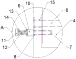
图4是图3的A处局部放大图。FIG. 4 is a partial enlarged view of part A of FIG. 3 .
图中:1、固定台,2、支架,3、安装槽,4、固定块,5、支撑板,6、转杆,7、固定孔,8、通孔,9、安装圆环,10、插销,11、螺帽,12、弹簧,13、第一凸块,14、第二凸块,15、安装孔。In the picture: 1. Fixing table, 2. Bracket, 3. Mounting slot, 4. Fixing block, 5. Support plate, 6. Rod, 7. Fixing hole, 8. Through hole, 9. Mounting ring, 10. Latch, 11, nut, 12, spring, 13, first bump, 14, second bump, 15, mounting hole.
具体实施方式Detailed ways
下面将对本实用新型实施例中的技术方案进行清楚、完整地描述,显然,所描述的实施例仅仅是本实用新型一部分实施例,而不是全部的实施例。基于本实用新型中的实施例,本领域普通技术人员在没有做出创造性劳动前提下所获得的所有其他实施例,都属于本实用新型保护的范围。The technical solutions in the embodiments of the present invention will be clearly and completely described below. Obviously, the described embodiments are only a part of the embodiments of the present invention, rather than all the embodiments. Based on the embodiments of the present invention, all other embodiments obtained by those of ordinary skill in the art without creative work fall within the protection scope of the present invention.
请参阅图1~4,本实用新型实施例中,安装角度可调的光伏模组,包括固定台1,固定台1的顶面安装有支架2,支架2的顶端成型有安装槽3,安装槽3内安装有固定块4,固定块4的下端为半圆形,固定块4的顶面安装有用于安装太阳能光伏板的支撑板5,固定块4内穿有转杆6,转杆6的左右两端与安装槽3内壁转动配合,固定块4的左侧成型有多个固定孔7,支架2的左侧成型有通孔8,通孔8与安装槽3相通,支架2的左侧连接有安装圆环9,安装圆环9与通孔8同心,安装圆环9内插有插销10,插销10的左侧连接有螺帽11,插销10的外套有弹簧12,弹簧12的右端与安装圆环9的左侧连接,弹簧12的左端与螺帽11的右侧连接,插销10通过弹簧12的弹力插接在某一个固定孔7内。Referring to FIGS. 1 to 4 , in the embodiment of the present invention, the photovoltaic module with an adjustable installation angle includes a fixing table 1 , a
安装圆环9的左侧成型有第一凸块13,螺帽11的右侧成型有第二凸块14,弹簧12的前端与第二凸块14卡接,弹簧12的后端与第一凸块13卡接。A
安装槽3内壁成型有安装孔15,转杆6设置在安装孔15内,转杆6的外壁与安装孔15的内壁转动配合。An
安装圆环9通过焊接的方式安装在支架2左侧。The
对于本领域技术人员而言,显然本实用新型不限于上述示范性实施例的细节,而且在不背离本实用新型的精神或基本特征的情况下,能够以其他的具体形式实现本实用新型。因此,无论从哪一点来看,均应将实施例看作是示范性的,而且是非限制性的,本实用新型的范围由所附权利要求而不是上述说明限定,因此旨在将落在权利要求的等同要件的含义和范围内的所有变化囊括在本实用新型内。It will be apparent to those skilled in the art that the present invention is not limited to the details of the above-described exemplary embodiments, and that the present invention may be implemented in other specific forms without departing from the spirit or essential characteristics of the present invention. Therefore, the embodiments are to be considered in all respects as exemplary and not restrictive, and the scope of the present invention is defined by the appended claims rather than the foregoing description, and it is therefore intended that the All changes within the meaning and range of the required equivalents are embraced within the present invention.
Claims (4)
Priority Applications (1)
| Application Number | Priority Date | Filing Date | Title |
|---|---|---|---|
| CN202020040907.1U CN211656057U (en) | 2020-01-09 | 2020-01-09 | Photovoltaic module with adjustable installation angle |
Applications Claiming Priority (1)
| Application Number | Priority Date | Filing Date | Title |
|---|---|---|---|
| CN202020040907.1U CN211656057U (en) | 2020-01-09 | 2020-01-09 | Photovoltaic module with adjustable installation angle |
Publications (1)
| Publication Number | Publication Date |
|---|---|
| CN211656057U true CN211656057U (en) | 2020-10-09 |
Family
ID=72704283
Family Applications (1)
| Application Number | Title | Priority Date | Filing Date |
|---|---|---|---|
| CN202020040907.1U Expired - Fee Related CN211656057U (en) | 2020-01-09 | 2020-01-09 | Photovoltaic module with adjustable installation angle |
Country Status (1)
| Country | Link |
|---|---|
| CN (1) | CN211656057U (en) |
Cited By (1)
| Publication number | Priority date | Publication date | Assignee | Title |
|---|---|---|---|---|
| CN116545352A (en) * | 2023-05-06 | 2023-08-04 | 山东高速建设管理集团有限公司 | Independently adjustable photovoltaic module of solar photovoltaic sound barrier |
-
2020
- 2020-01-09 CN CN202020040907.1U patent/CN211656057U/en not_active Expired - Fee Related
Cited By (2)
| Publication number | Priority date | Publication date | Assignee | Title |
|---|---|---|---|---|
| CN116545352A (en) * | 2023-05-06 | 2023-08-04 | 山东高速建设管理集团有限公司 | Independently adjustable photovoltaic module of solar photovoltaic sound barrier |
| CN116545352B (en) * | 2023-05-06 | 2024-04-19 | 山东高速建设管理集团有限公司 | An independent adjustable photovoltaic module for solar photovoltaic sound barrier |
Similar Documents
| Publication | Publication Date | Title |
|---|---|---|
| CN220775699U (en) | Photovoltaic power generation device with flexible support | |
| CN202302582U (en) | Connecting device and solar power generation equipment | |
| CN102044990B (en) | Installation method of frameless BIPV (building integrated photovoltaics) solar energy assembly | |
| CN217883320U (en) | A solar photovoltaic power generation device with adjustable angle | |
| CN210347736U (en) | Efficient heat dissipation meter box | |
| CN210273937U (en) | Concrete roof photovoltaic power station support | |
| CN221652534U (en) | A wall-mounted flat solar panel | |
| CN203325923U (en) | Solar support and solar assembly | |
| CN204418975U (en) | A kind of solar energy window | |
| CN209710022U (en) | A kind of solar panel that service efficiency is high | |
| CN211239759U (en) | An adjustable solar photovoltaic panel mount | |
| CN210807156U (en) | Adjustable new energy solar power generation device | |
| CN207782711U (en) | Photovoltaic distribution roof bracket flexible jig | |
| CN219802215U (en) | Photovoltaic power generation board installation construction platform | |
| CN102983186B (en) | Bracket for adjusting angle of photovoltaic cell panel | |
| CN217849327U (en) | Adjustable photovoltaic support | |
| CN215344446U (en) | A device capable of fixing photovoltaic modules | |
| CN206595958U (en) | A distributed photovoltaic off-grid solar power generation equipment | |
| CN206517349U (en) | A kind of high-resistance dense grid solar cell | |
| CN222915936U (en) | Elevation angle adjustable solar photovoltaic panel | |
| CN216599498U (en) | A manually adjustable photovoltaic panel bracket | |
| CN220935055U (en) | Wall-mounted photovoltaic module | |
| CN210724672U (en) | Solar power generation device convenient to change solar panel | |
| CN224037293U (en) | Photovoltaic BIPV board wind-resistant stable structure | |
| CN216751604U (en) | Energy-saving roofing peripheral equipment for green building |
Legal Events
| Date | Code | Title | Description |
|---|---|---|---|
| GR01 | Patent grant | ||
| GR01 | Patent grant | ||
| CF01 | Termination of patent right due to non-payment of annual fee | ||
| CF01 | Termination of patent right due to non-payment of annual fee |
Granted publication date: 20201009 |