CN211654427U - A cable recovery device for power engineering management - Google Patents
A cable recovery device for power engineering management Download PDFInfo
- Publication number
- CN211654427U CN211654427U CN202020370766.XU CN202020370766U CN211654427U CN 211654427 U CN211654427 U CN 211654427U CN 202020370766 U CN202020370766 U CN 202020370766U CN 211654427 U CN211654427 U CN 211654427U
- Authority
- CN
- China
- Prior art keywords
- plate
- recovery device
- engineering management
- roller
- bottom plate
- Prior art date
- Legal status (The legal status is an assumption and is not a legal conclusion. Google has not performed a legal analysis and makes no representation as to the accuracy of the status listed.)
- Expired - Fee Related
Links
Images



Classifications
-
- Y—GENERAL TAGGING OF NEW TECHNOLOGICAL DEVELOPMENTS; GENERAL TAGGING OF CROSS-SECTIONAL TECHNOLOGIES SPANNING OVER SEVERAL SECTIONS OF THE IPC; TECHNICAL SUBJECTS COVERED BY FORMER USPC CROSS-REFERENCE ART COLLECTIONS [XRACs] AND DIGESTS
- Y02—TECHNOLOGIES OR APPLICATIONS FOR MITIGATION OR ADAPTATION AGAINST CLIMATE CHANGE
- Y02W—CLIMATE CHANGE MITIGATION TECHNOLOGIES RELATED TO WASTEWATER TREATMENT OR WASTE MANAGEMENT
- Y02W30/00—Technologies for solid waste management
- Y02W30/50—Reuse, recycling or recovery technologies
- Y02W30/82—Recycling of waste of electrical or electronic equipment [WEEE]
Landscapes
- Manufacture Of Motors, Generators (AREA)
Abstract
本实用新型公开了一种电力工程管理线缆回收装置,包括收卷辊和底板,底板的上端面靠近左右两端位置均固定设置有支撑板,且两个支撑板相对的一面均设置有可转动的定位筒,收卷辊的两端分别套设在两侧的定位筒上,且位于右侧的定位筒驱动收卷辊转动,收卷辊的下方设置有可在底板的上表面前后移动的升降板。通过设置的两个支撑板滑动固定在导轨上,能够在对收卷辊进行安装和拆卸时将两个支撑板向两侧移动方便对收卷辊的安装与拆卸,并且对缠绕有线缆的收卷辊进行拆卸时,通过升降板将收卷辊顶起,再将两个支撑板移开,然后将升降板降下将其沿着导轨槽移出使得收卷辊的拆卸更加的轻松方便。

The utility model discloses a cable recovery device for power engineering management, which comprises a winding roller and a bottom plate. Support plates are fixedly arranged on the upper end surface of the bottom plate near the left and right ends, and the opposite sides of the two support plates are provided with adjustable support plates. The rotating positioning cylinder, the two ends of the winding roller are respectively sleeved on the positioning cylinders on both sides, and the positioning cylinder on the right side drives the winding roller to rotate. lift plate. The two supporting plates provided are slidably fixed on the guide rails, so that the two supporting plates can be moved to both sides during installation and disassembly of the take-up roller to facilitate the installation and disassembly of the take-up roller. When the take-up roller is disassembled, the take-up roller is lifted up by the lift plate, and then the two support plates are removed, and then the lift plate is lowered and moved out along the guide rail groove, which makes the disassembly of the take-up roller easier and more convenient.
Description
技术领域technical field
本实用新型涉及线缆回收技术领域,具体为一种电力工程管理线缆回收装置。The utility model relates to the technical field of cable recovery, in particular to a cable recovery device for power engineering management.
背景技术Background technique
在电力工程施工中会用到大量的线缆,而一些老旧的线缆或者多余的线缆利用不到时需要将线缆进行回收以方便下次使用或者进行回收用作新线缆的生产原料,而由于线缆往往比较长因此在线缆回收时需要通过收卷机构对线缆进行收卷实现对线缆的回收。A large number of cables are used in power engineering construction, and some old cables or redundant cables need to be recycled for the convenience of next use or for the production of new cables when they are not available. raw materials, and because the cables are often relatively long, it is necessary to wind the cables through a winding mechanism to realize the recovery of the cables when the cables are recovered.
本实用新型的申请人发现现有的线缆回收装置对于线缆的回收的收卷辊的安装和拆卸不方便,同时缠绕有线缆的收卷辊的重量较大在将其拆卸下来比较困难。The applicant of the present utility model finds that the existing cable recovery device is inconvenient to install and disassemble the winding roller for cable recovery, and at the same time, the winding roller wrapped with the cable is heavy and difficult to disassemble. .
实用新型内容Utility model content
本实用新型的目的在于提供一种电力工程管理线缆回收装置,旨在改善现有的线缆回收装置对于绕有线缆的收卷辊其拆卸下来比较困难的问题。The purpose of the utility model is to provide a cable recovery device for power engineering management, which aims to improve the problem that the existing cable recovery device is difficult to disassemble the winding roller with the cable wound.
本实用新型是这样实现的:The utility model is realized in this way:
一种电力工程管理线缆回收装置,包括收卷辊和底板,底板的上端面靠近左右两端位置均固定设置有支撑板,且两个支撑板相对的一面均设置有可转动的定位筒,收卷辊的两端分别套设在两侧的定位筒上,且位于右侧的定位筒驱动收卷辊转动,收卷辊的下方设置有可在底板的上表面前后移动的升降板,底板的上表面设置有两个为升降板前后移动导向的导轨槽,且底板的上表面靠近左右两端位置均固定设置有横向的导轨,两个支撑板的下端分别滑动安装在两个导轨上,通过设置的两个支撑板滑动固定在导轨上,能够在对收卷辊进行安装和拆卸时将两个支撑板向两侧移动方便对收卷辊的安装与拆卸,并且对缠绕有线缆的收卷辊进行拆卸时,通过升降板将收卷辊顶起,再将两个支撑板移开,然后将升降板降下将其沿着导轨槽移出使得收卷辊的拆卸更加的轻松方便。The utility model relates to a cable recovery device for power engineering management, comprising a winding roller and a bottom plate, the upper end surface of the bottom plate is fixedly provided with support plates near the left and right ends, and the opposite sides of the two support plates are provided with rotatable positioning cylinders. The two ends of the winding roller are respectively sleeved on the positioning cylinders on both sides, and the positioning cylinder on the right side drives the winding roller to rotate. Below the winding roller is a lifting plate that can move back and forth on the upper surface of the bottom plate. The upper surface of the base plate is provided with two guide rail grooves for guiding the front and rear movement of the lifting plate, and the upper surface of the bottom plate is fixed with horizontal guide rails near the left and right ends, and the lower ends of the two support plates are respectively slidably installed on the two guide rails. The two support plates provided are slidably fixed on the guide rail, so that the two support plates can be moved to both sides during installation and disassembly of the take-up roller to facilitate the installation and disassembly of the take-up roller. When the take-up roller is disassembled, the take-up roller is lifted up by the lifting plate, then the two support plates are removed, and then the lifting plate is lowered and moved out along the guide rail groove, which makes the disassembly of the take-up roller easier and more convenient.
进一步的,两个支撑板相反的一面均固定设置有锁止板,且锁止板上旋拧有顶紧在导轨上的螺丝,通过锁止板上的螺丝实现对支撑板的位置固定。Further, the opposite sides of the two support plates are fixedly provided with locking plates, and the locking plates are screwed with screws pressed against the guide rails, and the position of the support plates is fixed by the screws on the locking plates.
进一步的,升降板的上表面中间部位设置有对收卷辊进行定位支撑的定位槽,且升降板的下端面设置有均匀排布的移动支腿,移动支腿的下端设置有滚动轮,且滚动轮卡在导轨槽内,升降板通过滚动轮实现移动,并通过定位槽实现对收卷辊的放置。Further, the middle part of the upper surface of the lifting plate is provided with a positioning groove for positioning and supporting the winding roller, and the lower end surface of the lifting plate is provided with evenly arranged moving legs, and the lower ends of the moving legs are provided with rolling wheels, and The rolling wheel is stuck in the guide groove, the lifting plate is moved through the rolling wheel, and the winding roller is placed through the positioning groove.
进一步的,升降板的下端面中心设置有升降杆,且升降杆的上端固定设置有对升降板进行顶起支撑的顶板,升降杆的下端固定在底板上,通过升降杆实现对升降板的顶起和下降。Further, the center of the lower end face of the lifting plate is provided with a lifting rod, and the upper end of the lifting rod is fixedly provided with a top plate for lifting and supporting the lifting plate, and the lower end of the lifting rod is fixed on the bottom plate, and the lifting rod is used to realize the top of the lifting plate. up and down.
进一步的,位于右侧定位筒的一端设置有转轴,且定位筒外侧圆周面靠近转轴的一端设置有两个卡台,转轴的一端穿过支撑板固定套设有从动齿轮,且从动齿轮与电机输出轴上的主动齿轮啮合,电机固定在支撑板的右端面,通过电机驱动从动齿轮带动转轴和定位筒转动从而通过卡台带动收卷辊转动卷料。Further, one end of the positioning cylinder on the right side is provided with a rotating shaft, and one end of the outer circumferential surface of the positioning cylinder close to the rotating shaft is provided with two clamping platforms, one end of the rotating shaft is fixedly sleeved with a driven gear through the support plate, and the driven gear It meshes with the driving gear on the output shaft of the motor, the motor is fixed on the right end face of the support plate, and the driven gear is driven by the motor to drive the rotating shaft and the positioning cylinder to rotate, thereby driving the winding roller to rotate the material through the clamping table.
进一步的,收卷辊的两端均设置有挡板,且收卷辊中心孔的右端设置有与卡台配合的卡槽,收卷辊通过卡槽实现与卡台的卡接实现转动。Further, both ends of the winding roller are provided with baffle plates, and the right end of the central hole of the winding roller is provided with a clamping groove matched with the clamping table, and the winding roller is clamped with the clamping table to realize rotation through the clamping groove.
与现有技术相比,本实用新型的有益效果是:Compared with the prior art, the beneficial effects of the present utility model are:
本实用新型中通过设置的两个支撑板滑动固定在导轨上,能够在对收卷辊进行安装和拆卸时将两个支撑板向两侧移动方便对收卷辊的安装与拆卸,并且对缠绕有线缆的收卷辊进行拆卸时,通过升降板将收卷辊顶起,再将两个支撑板移开,然后将升降板降下将其沿着导轨槽移出使得收卷辊的拆卸更加的轻松方便。In the utility model, the two supporting plates are slidably fixed on the guide rail, so that the two supporting plates can be moved to both sides when the winding roller is installed and disassembled to facilitate the installation and disassembly of the winding roller, and the winding roller can be easily installed and removed. When the winding roller with cables is disassembled, the lifting plate is used to lift the winding roller, then the two support plates are removed, and then the lifting plate is lowered and moved out along the guide rail groove, which makes the removal of the winding roller easier. Easy and convenient.
附图说明Description of drawings
为了更清楚地说明本实用新型实施方式的技术方案,下面将对实施方式中所需要使用的附图作简单地介绍,应当理解,以下附图仅示出了本实用新型的某些实施例,因此不应被看作是对范围的限定,对于本领域普通技术人员来讲,在不付出创造性劳动的前提下,还可以根据这些附图获得其他相关的附图。In order to illustrate the technical solutions of the embodiments of the present invention more clearly, the accompanying drawings required in the embodiments will be briefly introduced below. It should be understood that the following drawings only show some embodiments of the present invention. Therefore, it should not be regarded as a limitation of the scope. For those of ordinary skill in the art, other related drawings can also be obtained from these drawings without any creative effort.
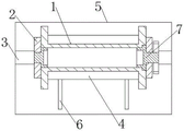
图1是本实用新型一种电力工程管理线缆回收装置的主视图;Fig. 1 is the front view of a kind of electric power engineering management cable recovery device of the present invention;
图2是本实用新型所示的一种电力工程管理线缆回收装置的俯视图;Fig. 2 is a top view of a power engineering management cable recovery device shown in the present utility model;
图3是本实用新型所示的一种电力工程管理线缆回收装置的升降板示意图;3 is a schematic diagram of a lift plate of a power engineering management cable recovery device shown in the present invention;
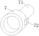
图4是本实用新型所示的一种电力工程管理线缆回收装置的定位筒示意图;4 is a schematic diagram of a positioning cylinder of a power engineering management cable recovery device shown in the present invention;
图5是本实用新型所示的一种电力工程管理线缆回收装置的收卷辊示意图。5 is a schematic diagram of a winding roller of a cable recovery device for power engineering management according to the present invention.
图中:1、收卷辊;11、挡板;12、卡槽;2、支撑板;21、锁止板;3、导轨;4、升降板;41、定位槽;42、移动支腿;43、顶板;44、升降杆;45、滚动轮;5、底板;6、导轨槽;7、定位筒;71、转轴;72、卡台;8、排料导槽。In the figure: 1. Rewinding roller; 11. Baffle plate; 12. Card slot; 2. Supporting plate; 21. Locking plate; 3. Guide rail; 4. Lifting plate; 43. Top plate; 44. Lifting rod; 45. Rolling wheel; 5. Bottom plate; 6. Guide rail groove; 7. Positioning cylinder; 71. Rotating shaft;
具体实施方式Detailed ways
为使本实用新型实施方式的目的、技术方案和优点更加清楚,下面将结合本实用新型实施方式中的附图,对本实用新型实施方式中的技术方案进行清楚、完整地描述,显然,所描述的实施方式是本实用新型一部分实施方式,而不是全部的实施方式。基于本实用新型中的实施方式,本领域普通技术人员在没有作出创造性劳动前提下所获得的所有其他实施方式,都属于本实用新型保护的范围。因此,以下对在附图中提供的本实用新型的实施方式的详细描述并非旨在限制要求保护的本实用新型的范围,而是仅仅表示本实用新型的选定实施方式。基于本实用新型中的实施方式,本领域普通技术人员在没有作出创造性劳动前提下所获得的所有其他实施方式,都属于本实用新型保护的范围。In order to make the purposes, technical solutions and advantages of the embodiments of the present invention more clear, the technical solutions in the embodiments of the present invention will be clearly and completely described below with reference to the accompanying drawings in the embodiments of the present invention. Obviously, the described The embodiments of the present invention are a part of the embodiments of the present invention, but not all of the embodiments. Based on the embodiments of the present invention, all other embodiments obtained by those of ordinary skill in the art without creative work fall within the protection scope of the present invention. Accordingly, the following detailed description of the embodiments of the invention provided in the accompanying drawings is not intended to limit the scope of the invention as claimed, but is merely representative of selected embodiments of the invention. Based on the embodiments of the present invention, all other embodiments obtained by those of ordinary skill in the art without creative work fall within the protection scope of the present invention.
实施例1,具体请参照图1和图2所示,一种电力工程管理线缆回收装置,包括收卷辊1和底板5,底板5的上端面靠近左右两端位置均固定设置有支撑板2,且两个支撑板2相对的一面均设置有可转动的定位筒7,收卷辊1的两端分别套设在两侧的定位筒7上,且位于右侧的定位筒7驱动收卷辊1转动,收卷辊1的下方设置有可在底板5的上表面前后移动的升降板4,底板5的上表面设置有两个为升降板4前后移动导向的导轨槽6,且底板5的上表面靠近左右两端位置均固定设置有横向的导轨3,两个支撑板2的下端分别滑动安装在两个导轨3上,通过设置的两个支撑板2滑动固定在导轨3上,能够在对收卷辊1进行安装和拆卸时将两个支撑板2向两侧移动方便对收卷辊1的安装与拆卸,并且对缠绕有线缆的收卷辊1进行拆卸时,通过升降板4将收卷辊1顶起,再将两个支撑板2移开,然后将升降板4降下将其沿着导轨槽6移出使得收卷辊1的拆卸更加的轻松方便。
具体请参照图1所示,两个支撑板2相反的一面均固定设置有锁止板21,且锁止板21上旋拧有顶紧在导轨3上的螺丝,通过锁止板21上的螺丝实现对支撑板2的位置固定。For details, please refer to FIG. 1 , the opposite sides of the two
具体请参照图3所示,升降板4的上表面中间部位设置有对收卷辊1进行定位支撑的定位槽41,且升降板4的下端面设置有均匀排布的移动支腿42,移动支腿42的下端设置有滚动轮45,且滚动轮45卡在导轨槽6内,升降板4通过滚动轮45实现移动,并通过定位槽41实现对收卷辊1的放置,升降板4的下端面中心设置有升降杆44,且升降杆44的上端固定设置有对升降板4进行顶起支撑的顶板43,升降杆44的下端固定在底板5上,通过升降杆44实现对升降板4的顶起和下降。For details, please refer to FIG. 3 , the middle part of the upper surface of the
具体请参照图4所示,位于右侧定位筒7的一端设置有转轴71,且定位筒7外侧圆周面靠近转轴71的一端设置有两个卡台72,转轴71的一端穿过支撑板2固定套设有从动齿轮,且从动齿轮与电机输出轴上的主动齿轮啮合,电机固定在支撑板2的右端面,通过电机驱动从动齿轮带动转轴71和定位筒7转动从而通过卡台72带动收卷辊1转动卷料。For details, please refer to FIG. 4 , a rotating
具体请参照图5所示,收卷辊1的两端均设置有挡板11,且收卷辊1中心孔的右端设置有与卡台72配合的卡槽12,收卷辊1通过卡槽12实现与卡台72的卡接实现转动。For details, please refer to FIG. 5 , baffles 11 are provided at both ends of the winding
工作原理:在进行线缆回收时,通过电机驱动从动齿轮带动转轴71和定位筒7转动从而通过卡台72带动收卷辊1转动对线缆进行收卷,在线缆回收利用结束后,通过升降杆44将升降板4顶起对收卷辊1进行支撑,将两侧的支撑板2向两侧移开,然后将升降杆44降下使得升降板4降下将其沿着导轨槽6移出然后对收卷辊1吊出。Working principle: When the cable is recovered, the driven gear is driven by the motor to drive the rotating
通过上述设计得到的装置已基本能满足现有的线缆回收装置对于绕有线缆的收卷辊其拆卸轻松方便的使用,但本着进一步完善其功能的宗旨,设计者对该装置进行了进一步的改良。The device obtained through the above design can basically meet the requirements of the existing cable recovery device for the easy and convenient use of the reeling roller with the cable wound. However, in order to further improve its function, the designer has carried out further improvements.
以上所述仅为本实用新型的优选实施方式而已,并不用于限制本实用新型,对于本领域的技术人员来说,本实用新型可以有各种更改和变化。凡在本实用新型的精神和原则之内,所作的任何修改、等同替换、改进等,均应包含在本实用新型的保护范围之内。The above descriptions are only preferred embodiments of the present invention, and are not intended to limit the present invention. For those skilled in the art, the present invention may have various modifications and changes. Any modification, equivalent replacement, improvement, etc. made within the spirit and principle of the present invention shall be included in the protection scope of the present invention.
Claims (6)
Priority Applications (1)
| Application Number | Priority Date | Filing Date | Title |
|---|---|---|---|
| CN202020370766.XU CN211654427U (en) | 2020-03-23 | 2020-03-23 | A cable recovery device for power engineering management |
Applications Claiming Priority (1)
| Application Number | Priority Date | Filing Date | Title |
|---|---|---|---|
| CN202020370766.XU CN211654427U (en) | 2020-03-23 | 2020-03-23 | A cable recovery device for power engineering management |
Publications (1)
| Publication Number | Publication Date |
|---|---|
| CN211654427U true CN211654427U (en) | 2020-10-09 |
Family
ID=72688235
Family Applications (1)
| Application Number | Title | Priority Date | Filing Date |
|---|---|---|---|
| CN202020370766.XU Expired - Fee Related CN211654427U (en) | 2020-03-23 | 2020-03-23 | A cable recovery device for power engineering management |
Country Status (1)
| Country | Link |
|---|---|
| CN (1) | CN211654427U (en) |
Cited By (1)
| Publication number | Priority date | Publication date | Assignee | Title |
|---|---|---|---|---|
| CN115744078A (en) * | 2022-11-16 | 2023-03-07 | 上海科大重工集团有限公司 | Non-stop roller quick-change platform |
-
2020
- 2020-03-23 CN CN202020370766.XU patent/CN211654427U/en not_active Expired - Fee Related
Cited By (1)
| Publication number | Priority date | Publication date | Assignee | Title |
|---|---|---|---|---|
| CN115744078A (en) * | 2022-11-16 | 2023-03-07 | 上海科大重工集团有限公司 | Non-stop roller quick-change platform |
Similar Documents
| Publication | Publication Date | Title |
|---|---|---|
| CN111745833A (en) | Four-roll down-pressing stone diamond wire cutting machine | |
| CN218403396U (en) | Steel hoisting device for steel structure factory building assembly | |
| CN110803584A (en) | A winding device for cable production | |
| CN217051114U (en) | Cable processing take-up device convenient to quick assembly disassembly | |
| CN209566013U (en) | A convenient detachable roll paper device for sandpaper production | |
| CN221295930U (en) | A cable pulley for a light load crane system | |
| CN214653240U (en) | Hoist is with reel convenient to fix | |
| CN221543642U (en) | Cable reel winding displacement device | |
| CN221853815U (en) | A cable reeling and unreeling mechanism for convenient loading and unloading of cable reels | |
| CN220502251U (en) | Cable winch for well repair | |
| CN219279140U (en) | a coil mechanism | |
| CN223734829U (en) | Auxiliary equipment for overhauling the rotor of a mining truck engine | |
| CN221836475U (en) | Cable winch capable of preventing cable from loosening | |
| CN221929188U (en) | Power maintenance cable bracket | |
| CN219448666U (en) | Microfiber leather winding mechanism | |
| CN219293637U (en) | Efficient burnishing device for optical axis production | |
| CN223646782U (en) | A fabric roll clamping structure for a dyeing machine | |
| CN215626064U (en) | A hoist sprocket base with stable structure | |
| CN111745842A (en) | Three-roll down-pressing stone diamond wire cutting machine | |
| CN218778520U (en) | Wire rewinding machine convenient to use | |
| CN221962001U (en) | Plastic coiled material static electricity removing device | |
| CN216304106U (en) | Fixing device for circular knitting machine | |
| CN218289771U (en) | A coiling device for sheet metal production | |
| CN224132413U (en) | A cable unwinding rack | |
| CN223655259U (en) | Wind turbine tower body coating support device |
Legal Events
| Date | Code | Title | Description |
|---|---|---|---|
| GR01 | Patent grant | ||
| GR01 | Patent grant | ||
| CF01 | Termination of patent right due to non-payment of annual fee |
Granted publication date: 20201009 |
|
| CF01 | Termination of patent right due to non-payment of annual fee |