CN211647678U - Clutch device of lock body - Google Patents
Clutch device of lock body Download PDFInfo
- Publication number
- CN211647678U CN211647678U CN202020104042.0U CN202020104042U CN211647678U CN 211647678 U CN211647678 U CN 211647678U CN 202020104042 U CN202020104042 U CN 202020104042U CN 211647678 U CN211647678 U CN 211647678U
- Authority
- CN
- China
- Prior art keywords
- clutch
- rotor
- seat
- lock body
- lock
- Prior art date
- Legal status (The legal status is an assumption and is not a legal conclusion. Google has not performed a legal analysis and makes no representation as to the accuracy of the status listed.)
- Expired - Fee Related
Links
- 229910000831 Steel Inorganic materials 0.000 claims description 7
- 238000009434 installation Methods 0.000 claims description 7
- 239000010959 steel Substances 0.000 claims description 7
- 238000000926 separation method Methods 0.000 abstract 9
- 230000001360 synchronised effect Effects 0.000 abstract 1
- 238000010586 diagram Methods 0.000 description 2
- 238000004519 manufacturing process Methods 0.000 description 2
- 238000003756 stirring Methods 0.000 description 2
- 230000007547 defect Effects 0.000 description 1
- 230000000694 effects Effects 0.000 description 1
- 230000000149 penetrating effect Effects 0.000 description 1
Images



Landscapes
- Mechanical Operated Clutches (AREA)
Abstract
The utility model relates to a clutch device of lock body, including separation and reunion seat and rotor, separation and reunion seat is provided with the separation and reunion round pin that can insert or withdraw from the rotor, and when separation and reunion round pin inserted the rotor, the rotor can follow separation and reunion seat synchronous rotation, and when separation and reunion round pin withdrawed from the rotor, the rotor can rotate with separation and reunion seat relatively, and its characterized in that, the rotor is provided with the draw-in groove, is provided with the bayonet lock on the separation and reunion seat, is provided with the elastic component between separation and reunion seat and the bayonet lock, and under; when the rotor rotates along the counterclockwise direction around the central shaft of the rotor, the clutch seat and the rotor synchronously rotate; when the rotor rotates around the central shaft in clockwise direction, the bayonet lock is separated from the bayonet lock by overcoming the action of the elastic element, and the rotor and the clutch base rotate relatively. The utility model has the advantages of simple structure, simple to operate.
Description
Technical Field
The utility model relates to a clutch device of a lock body.
Background
In order to enhance the anti-theft effect, the existing anti-theft door lock adopts a clutch structure, the commonly used clutch comprises a clutch seat, a rotating sleeve and a clutch device, the rotating sleeve is rotatably arranged on the clutch seat, two ends of the rotating sleeve are respectively connected with a handle or a twist key through square steel, the clutch device is arranged between the clutch seat and the rotating sleeve, the rotating sleeve can rotate relative to the clutch seat along the central shaft of the rotating sleeve through the clutch device or can synchronously rotate along with the clutch seat, namely, after the door lock is locked, the handle and the lock body are not linked under the action of the clutch, when people rotate the handle outside the door, the handle can only idle and cannot open the door, thereby avoiding the possibility that the lock body is damaged by violence, and after a key is inserted into the lock core or an electronic command is sent to unlock the lock body, the handle and the lock body can be linked under the action of the clutch.
The existing clutch structure has the defects that the clutch installed in the lock body needs to be provided with two pieces of square steel to be connected with the outer handle of the door and the inner handle of the door respectively, so that the structure of the clutch is complex on one hand, and the installation is inconvenient on the other hand. Therefore, there is a need for an improved clutch device for an existing lock body.
SUMMERY OF THE UTILITY MODEL
An object of the utility model is to provide a simple structure, simple to operate's clutch of lock body.
In order to achieve the above purpose, the utility model adopts the following technical scheme:
a clutch device of a lock body comprises a clutch seat and a rotor, wherein the clutch seat is provided with a clutch pin which can be inserted into or withdrawn from the rotor, when the clutch pin is inserted into the rotor, the rotor can synchronously rotate along with the clutch seat, and when the clutch pin is withdrawn from the rotor, the rotor can relatively rotate with the clutch seat; when the rotor rotates along the counterclockwise direction around the central shaft of the rotor, the clutch seat and the rotor synchronously rotate; when the rotor rotates around the central shaft in clockwise direction, the bayonet lock is separated from the bayonet lock by overcoming the action of the elastic element, and the rotor and the clutch base rotate relatively.
The utility model has the advantages of simple structure, simple to operate.
The utility model discloses the accessible improves with following scheme:
the clutch seat is provided with a mounting cavity corresponding to the clamping groove, a first end of the clamping pin is hinged to the mounting cavity, and a second end of the clamping pin can switch positions between the mounting cavity and the clamping groove; one end of the elastic piece abuts against the side face, facing the mounting cavity, of the bayonet lock, and the other end of the elastic piece abuts against the mounting cavity.
The clutch seat is provided with a mounting cavity corresponding to the clamping groove, a first end of the clamping pin is hinged to the mounting cavity, and a second end of the clamping pin can switch positions between the mounting cavity and the clamping groove; the elastic part is a V-shaped elastic part with two free arms, the junction of the two free arms of the elastic part is rotatably arranged in the installation cavity, one free arm of the elastic part abuts against the side surface of the bayonet lock facing the installation cavity, and the other free arm abuts against the installation cavity.
The clutch seat is formed by combining an upper seat and a lower seat and forms a through hole which runs through the respective side surfaces of the upper seat and the lower seat.
The rotor is provided with two mounting holes for square steel to pass through, and the two mounting holes are arranged in the through hole and correspond to the upper seat and the lower seat.
The clutch pin is withdrawn from the rotor and retracted in the clutch seat under the action of the spring; under the pushing of the pushing mechanism, the clutch pin is inserted into the clamping hole against the action of the spring.
The pushing mechanism comprises a motor which is installed and fixed inside the lock body, the motor is connected with a push plate through a speed reducing mechanism, the push plate is an arc-shaped plate with a central shaft coaxial with a rotating central shaft of the clutch base, and the push plate moves up and down along the axial direction of the clutch pin under the action of the motor.
The lock body is provided with a lock bolt, a clutch shifting piece which is matched and linked with the lock bolt is sleeved on the clutch seat, and the rotation of the clutch seat drives the clutch shifting piece to rotate along with the clutch shifting piece so as to lock or unlock the lock bolt.
Drawings
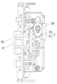
Fig. 1 is a schematic three-dimensional state diagram (unlocked state) of the overall structure of the lock body in the embodiment.
Fig. 2 is a schematic three-dimensional state (locked state) of the overall structure of the lock body in the embodiment.
Fig. 3 is a partially exploded view of the structure of fig. 2.
Fig. 4 is a structural schematic diagram of the clutch device in the embodiment in an exploded state.
FIG. 5 is a schematic cross-sectional view showing the unlocked state of the clutch device in the embodiment (the rotor rotates counterclockwise to rotate synchronously with the clutch base, and the rotor rotates clockwise to rotate relatively with the clutch base to idle).
FIG. 6 is a schematic cross-sectional view showing the idling state of the clutch device in the embodiment (the rotor rotates clockwise to rotate relative to the clutch base).
Fig. 7 is a schematic sectional view showing the unlocked state of the clutch device according to the embodiment (the clutch pin is inserted into the engaging hole).
Detailed Description
As shown in fig. 1 to 7, the clutch device of the lock body comprises a clutch base 1 and a rotor 3.
The clutch seat 1 is provided with a clutch pin 5 which can be inserted into or withdrawn from the rotor 3, when the clutch pin 5 is inserted into the rotor 3, the rotor 3 can synchronously rotate along with the clutch seat 1, when the clutch pin 5 is withdrawn from the rotor 3, the rotor 3 can relatively rotate with the clutch seat 1, specifically, the rotor 3 is provided with a clamping hole 31, the lock body is provided with a pushing mechanism 7, a spring 6 is arranged between the clutch pin 5 and the clutch seat 1, and the clutch pin 5 is withdrawn from the rotor 3 and retracted into the clutch seat 1 under the action of the spring 6; under the urging of the urging mechanism 7, the clutch pin 5 is inserted into the card hole 31 against the action of the spring 6.
The pushing mechanism 7 comprises a motor 71 which is fixedly arranged in the lock body, the motor 71 is connected with a push plate 72 through a speed reducing mechanism, the push plate 72 is an arc-shaped plate with a central shaft coaxial with a rotating central shaft of the clutch base 1, and the push plate 72 moves up and down along the axial direction of the clutch pin 5 under the action of the motor 71.
When the lock is used, the handle is connected with the rotor 3 through square steel, the lock body is provided with the lock bolt 8, the clutch base 1 is sleeved with the clutch stirring piece 81 which is in matched linkage with the lock bolt 8, and the clutch base 1 rotates to drive the clutch stirring piece 81 to rotate together to lock or unlock the lock bolt 8. When the lock is locked, the rotor 3 can rotate relative to the clutch seat 1, the rotor 3 and the clutch seat 1 are in a free state, namely the handle and the lock body are in a free state and can only idle, and therefore the anti-theft function is achieved. When the lock needs to be unlocked, after the lock body is unlocked by sending an electronic command in a mode of inserting a key into the lock cylinder or pressing a fingerprint and the like, the pushing mechanism 7 pushes the clutch pin 5 to overcome the action of the spring 6 and insert the clutch pin into the clamping hole 31, and the handle is linked with the lock bolt 8 through square steel, the rotor 3, the clutch seat 1 and the clutch toggle piece 81, so that unlocking is realized.
Under the structure, if an electronic command is sent out in a mode of inserting a key into a lock cylinder or pressing a fingerprint and the like, the lock body cannot be locked, so that in the embodiment, the rotor 3 is provided with the clamping groove 32, the clamping pin 11 is arranged on the clutch seat 1, the elastic element 12 is arranged between the clutch seat 1 and the clamping pin 11, and the clamping pin 11 is clamped in the clamping groove 32 under the action of the elastic element 12 in a normal state; when the rotor 3 rotates along the counterclockwise direction around the central shaft, the clutch base 1 and the rotor 3 rotate synchronously, as shown in figure 5; when rotor 3 is rotated clockwise about its central axis, bayonet 11 is moved away from bayonet 32 against the action of resilient member 12, and rotor 3 is rotated relative to clutch plate 1, as shown in figure 6. When the lock needs to be locked, the handle is only required to be rotated anticlockwise (namely lifted upwards), the bayonet lock 11 is clamped in the bayonet lock 32 under the action of the elastic piece 12, the clutch base 1 and the rotor 3 synchronously rotate and drive the lock bolt 8 to perform locking action, and an electronic instruction is not required to be sent out in a mode of inserting a key into the lock cylinder or pressing a fingerprint and the like so as to lock the lock body. After locking, the rotor 3 can not rotate anticlockwise, correspondingly, the handle can not be lifted up any more, the rotor 3 can only rotate relative to the clutch base 1 in the clockwise direction to handle the idle rotation state, and the anti-theft function is realized, as shown in fig. 7.
More specifically, the clutch seat 1 is provided with a mounting cavity 13 corresponding to the clamping groove 32, a first end of the clamping pin 11 is hinged in the mounting cavity 13, and a second end of the clamping pin 11 can switch positions between the mounting cavity 13 and the clamping groove 32; the elastic element 12 may be a common spring, one end of which abuts against the side of the bayonet 11 facing the mounting cavity 13, and the other end of the elastic element 12 abuts against the mounting cavity 13. Of course, it is preferable that the elastic member 12 is a V-shaped elastic member having two free arms, as shown in the drawings, and the intersection of the two free arms of the elastic member is rotatably mounted in the mounting cavity 13, and one of the free arms of the elastic member 12 abuts against the side of the latch 11 facing the mounting cavity 13, and the other free arm abuts against the mounting cavity 13.
In addition, the clutch seat 1 is composed of an upper seat and a lower seat which are combined to form through holes penetrating through the side surfaces of the upper seat and the lower seat, the rotor 3 is totally arranged in the through holes and is arranged corresponding to the upper seat and the lower seat, and the rotor 3 is provided with a mounting hole 33 for square steel to penetrate through. So as to facilitate production, manufacture and assembly.
Claims (8)
1. A clutch device of a lock body comprises a clutch seat and a rotor, wherein the clutch seat is provided with a clutch pin which can be inserted into or withdrawn from the rotor, when the clutch pin is inserted into the rotor, the rotor can synchronously rotate along with the clutch seat, and when the clutch pin is withdrawn from the rotor, the rotor can relatively rotate with the clutch seat; when the rotor rotates along the counterclockwise direction around the central shaft of the rotor, the clutch seat and the rotor synchronously rotate; when the rotor rotates around the central shaft in clockwise direction, the bayonet lock is separated from the bayonet lock by overcoming the action of the elastic element, and the rotor and the clutch base rotate relatively.
2. The clutch device of a lock body according to claim 1, wherein the clutch base is provided with a mounting cavity corresponding to the clamping groove, a first end of the clamping pin is hinged in the mounting cavity, and a second end of the clamping pin can switch positions between the mounting cavity and the clamping groove; one end of the elastic piece abuts against the side face, facing the mounting cavity, of the bayonet lock, and the other end of the elastic piece abuts against the mounting cavity.
3. The clutch device of a lock body according to claim 1, wherein the clutch base is provided with a mounting cavity corresponding to the clamping groove, a first end of the clamping pin is hinged in the mounting cavity, and a second end of the clamping pin can switch positions between the mounting cavity and the clamping groove; the elastic part is a V-shaped elastic part with two free arms, the junction of the two free arms of the elastic part is rotatably arranged in the installation cavity, one free arm of the elastic part abuts against the side surface of the bayonet lock facing the installation cavity, and the other free arm abuts against the installation cavity.
4. The clutching device of a lock body of claim 1, wherein the clutch base is formed by combining an upper base and a lower base and has a through hole formed through each side of the upper base and the lower base.
5. The clutched device of claim 4, wherein two of the rotors are disposed in the through hole and corresponding to the upper and lower seats, and the rotor is formed with a mounting hole for square steel to pass through.
6. A clutch device of a lock body according to any one of the claims 1 to 5, characterized in that the rotor is further provided with a clamping hole, the lock body is further provided with a pushing mechanism, a spring is arranged between the clutch pin and the clutch seat, and the clutch pin is withdrawn from the rotor and retracted in the clutch seat under the action of the spring; under the pushing of the pushing mechanism, the clutch pin is inserted into the clamping hole against the action of the spring.
7. The clutch device of a lock body according to claim 6, wherein the pushing mechanism comprises a motor fixed inside the lock body, the motor is connected with a push plate through a speed reducing mechanism, the push plate is an arc-shaped plate with a central axis coaxial with a rotating central axis of the clutch base, and the push plate moves up and down along the axial direction of the clutch pin under the action of the motor.
8. The clutch device of a lock body of claim 6, wherein the lock body is provided with a lock bolt, the clutch base is sleeved with a clutch toggle member cooperating with the lock bolt, and the rotation of the clutch base drives the clutch toggle member to rotate together to lock or unlock the lock bolt.
Priority Applications (1)
| Application Number | Priority Date | Filing Date | Title |
|---|---|---|---|
| CN202020104042.0U CN211647678U (en) | 2020-01-17 | 2020-01-17 | Clutch device of lock body |
Applications Claiming Priority (1)
| Application Number | Priority Date | Filing Date | Title |
|---|---|---|---|
| CN202020104042.0U CN211647678U (en) | 2020-01-17 | 2020-01-17 | Clutch device of lock body |
Publications (1)
| Publication Number | Publication Date |
|---|---|
| CN211647678U true CN211647678U (en) | 2020-10-09 |
Family
ID=72684340
Family Applications (1)
| Application Number | Title | Priority Date | Filing Date |
|---|---|---|---|
| CN202020104042.0U Expired - Fee Related CN211647678U (en) | 2020-01-17 | 2020-01-17 | Clutch device of lock body |
Country Status (1)
| Country | Link |
|---|---|
| CN (1) | CN211647678U (en) |
Cited By (1)
| Publication number | Priority date | Publication date | Assignee | Title |
|---|---|---|---|---|
| CN111042666A (en) * | 2020-01-17 | 2020-04-21 | 李浩远 | Clutch device of lock body |
-
2020
- 2020-01-17 CN CN202020104042.0U patent/CN211647678U/en not_active Expired - Fee Related
Cited By (1)
| Publication number | Priority date | Publication date | Assignee | Title |
|---|---|---|---|---|
| CN111042666A (en) * | 2020-01-17 | 2020-04-21 | 李浩远 | Clutch device of lock body |
Similar Documents
| Publication | Publication Date | Title |
|---|---|---|
| CN201507172U (en) | Flexible and lightweight magnetic card smart lock | |
| WO2015010513A1 (en) | High-security electronic lock cylinder with clutch | |
| CN101581167B (en) | Electronic door lock with electromechanical conversion unlocking motor | |
| CN104790758B (en) | A kind of based on the pick-proof lock spirally returning clutch module and bi-motor module | |
| CN111042666A (en) | Clutch device of lock body | |
| CN103233624B (en) | Electronic anti-theft lock | |
| CN212317685U (en) | Door lock and door body using same | |
| CN108193939B (en) | Multifunctional built-in door lock clutch module | |
| CN107989490B (en) | Double-lock-core electric cabinet lock | |
| CN221682728U (en) | Padlock | |
| CN206091573U (en) | Prevent locks that unblanks through cat eye | |
| CN221856462U (en) | Lockset with automatic unlocking function | |
| CN217028456U (en) | Lock body and electronic lock | |
| CN218029580U (en) | Electric lock body for preventing power failure from being locked | |
| CN215520382U (en) | Anti-theft door lock | |
| CN216811300U (en) | Anti-riot lock body | |
| CN107386791B (en) | Double-sided handle lock | |
| CN113294030B (en) | Intelligent door lock | |
| CN214463333U (en) | Lock body | |
| CN213449842U (en) | Lock with escape function | |
| CN107130843B (en) | Clutch device of intelligent anti-theft lock body | |
| CN218912520U (en) | Novel interior handle of ecological lock | |
| CN201129073Y (en) | a kind of lock | |
| CN210460228U (en) | Door lock with handle | |
| CN207686447U (en) | A kind of novel push-draw electronic lock assembly |
Legal Events
| Date | Code | Title | Description |
|---|---|---|---|
| GR01 | Patent grant | ||
| GR01 | Patent grant | ||
| TR01 | Transfer of patent right |
Effective date of registration: 20211215 Address after: 528400 7 / F, building D, Yuema Industrial Park, Fuxi, Xiaolan Town, Zhongshan City, Guangdong Province Patentee after: Guangdong Yuema Intelligent Technology Co.,Ltd. Address before: No.35 Guangshan Road, Guangfeng Industrial Park, Longxi, Xiaolan Town, Zhongshan City, Guangdong Province 528400 Patentee before: Li Haoyuan |
|
| TR01 | Transfer of patent right | ||
| CF01 | Termination of patent right due to non-payment of annual fee |
Granted publication date: 20201009 Termination date: 20220117 |
|
| CF01 | Termination of patent right due to non-payment of annual fee |