CN211638659U - Welding die for temperature-equalizing plate - Google Patents
Welding die for temperature-equalizing plate Download PDFInfo
- Publication number
- CN211638659U CN211638659U CN202020085410.1U CN202020085410U CN211638659U CN 211638659 U CN211638659 U CN 211638659U CN 202020085410 U CN202020085410 U CN 202020085410U CN 211638659 U CN211638659 U CN 211638659U
- Authority
- CN
- China
- Prior art keywords
- plate
- die
- welding
- thickness
- sinks
- Prior art date
- Legal status (The legal status is an assumption and is not a legal conclusion. Google has not performed a legal analysis and makes no representation as to the accuracy of the status listed.)
- Active
Links
Images



Landscapes
- Moulds For Moulding Plastics Or The Like (AREA)
Abstract
The utility model relates to a mould, in particular to temperature-uniforming plate welding mould. The utility model provides a samming board welding mould, includes die block, limiting plate, clamp plate, be equipped with a plurality of die districts on the die block, the die district is the recess that sinks that the die block set up on the surface, and it sinks highly to be greater than the thickness of the samming board of required welding, limiting plate thickness slightly is less than the height that sinks in die district, and the limiting plate front end is provided with spacing fork. The utility model discloses simple structure can once only weld polylith temperature equalization board, through the range upon range of combination of polylith die block and limiting plate, increase welding quantity that can step forward again. The setting of spacing fork can easily make two plate body edges align about the temperature-uniforming plate, stop basically because of the edge is not neat, the welding quality that the inaccurate production in location is not passed, lead to the vacuum treatment in later stage to appear the condition emergence such as defect, weeping.
Description
Technical Field
The utility model relates to a mould, in particular to temperature-uniforming plate welding mould.
Background
Along with the increasingly powerful chip function of electronic equipment, the situation of generating heat is also more and more serious, especially along with the development of 5G communication network, 5G smart mobile is developing towards frivolousization, intellectuality and multi-functionalization etc. and the high integration of equipment has proposed higher performance requirement and challenge to the heat dissipation processing technology of cell-phone material. The traditional heat dissipation technology cannot meet the increasing power heat dissipation requirement, and at present, the relatively good heat dissipation technology can be a temperature equalizing plate, and the temperature equalizing plate is a heat dissipation device, so that heat can be taken away quickly in work, and the heat can be prevented from being concentrated on a heat source. The structure of the temperature equalizing plate is approximately two upper and lower radiating plate bodies, and the heating area and the radiating area inside the temperature equalizing plate are covered. Because its inside needs the evacuation, consequently the welding quality and the sealing quality of two blocks of plate bodies are crucial, and the welding process is usually for after the edge of two blocks of plate bodies about sets up the solder, high temperature press welding forms, and the quality of welding process will directly decide the quality of monoblock samming board. The problem that an upper sheet and a lower sheet are difficult to position generally exists in the industry, and is mainly reflected in that the difference between the thermal expansion coefficients of a copper alloy of a temperature equalizing plate and a graphite material of a welding mold is large in the welding process, the copper alloy of the temperature equalizing plate and the graphite material of the welding mold cannot be synchronized at high temperature, and when the temperature equalizing plate is blocked by the graphite mold with small expansion degree due to large thermal expansion degree, bulging and deformation are easy to generate, so that poor welding is caused, and therefore a temperature equalizing plate welding mold with good welding quality and high efficiency is urgently needed at present.
Disclosure of Invention
For solving the technical problem, the utility model provides a welding quality is good, efficient samming board.
The utility model discloses technical scheme as follows: the utility model provides a samming board welding mould, includes die block, limiting plate, clamp plate, be equipped with a plurality of die districts on the die block, the die district is the recess that sinks that the die block set up on the surface, and it sinks highly to be greater than the thickness of the samming board of required welding, limiting plate thickness slightly is less than the height that sinks in die district, and the limiting plate front end is provided with spacing fork.
As a further technical scheme of the utility model, the position outside the die area of die block is equipped with the through-hole, also be equipped with on the clamp plate body with the die block on through-hole position and the equal unanimous through-hole of size.
As a further technical scheme of the utility model, limiting plate outer end both sides are provided with the lug the overall shape of spacing fork is unanimous with the interior overall shape in die district, the shape that spacing fork and die district lateral wall enclose is unanimous with the overall shape of samming board.
As a further technical scheme of the utility model, still be provided with the samming board intake pipe recess on the die area.
As a further technical scheme of the utility model, the back of die block and the surface of clamp plate are provided with the lug, the shape and the position of lug with the shape that spacing fork and die district lateral wall enclose is unanimous, the thickness of lug is greater than the die district and sinks the difference of height and required welded samming plate thickness.
The clamping device further comprises a fastening screw and a fastening nut, and the outer diameter of the fastening screw is consistent with the inner diameter of the through hole.
As a further technical solution of the present invention, the utility model discloses an another technical scheme: in order to further reduce the processing difficulty and prolong the service life, the scheme does not arrange a convex block on the back surface of the bottom die and the surface of the pressing plate, but independently manufacture a pressing block with the same space shape formed by the limiting fork and the side wall of the die area, and the thickness of the pressing block is larger than the difference between the sinking height of the die area and the thickness of the temperature equalizing plate required to be welded. Other configurations are consistent with the foregoing.
The utility model discloses the during operation inserts the die district of die block with the limiting plate in, puts into the region that spacing fork and die district lateral wall enclose with two plate bodys of the temperature equalization board of solder are placed at the edge, puts into the lug and pushes down the temperature equalization board, then covers the clamp plate, inserts fastening screw through the through-hole and adopts fastening nut to screw up from top to bottom after, can take the limiting plate out this moment, then puts into the interior heat-welding of high-temperature furnace with whole mould.
The utility model has the advantages as follows: the utility model discloses simple structure can once only weld polylith temperature equalization board, through the range upon range of combination of polylith die block and limiting plate, increase welding quantity that can step forward again. The setting of spacing fork can easily make two plate body edges align about the temperature-uniforming plate, stop basically because of the edge is not neat, the welding quality that the inaccurate production in location is not passed, lead to the vacuum treatment in later stage to appear the condition emergence such as defect, weeping. Meanwhile, when the temperature equalizing plate and the die are placed in a high-temperature furnace for heating, three edges of the temperature equalizing plate are free of blocking after the limiting plate is taken out, the temperature equalizing plate can expand freely, the problems of bulging, deformation and the like caused by inconsistent expansion coefficients are thoroughly solved, and the welding quality of products is greatly improved.
Obviously, among the technical scheme of the utility model, the shape that spacing fork and die district lateral wall enclose is different according to the shape of temperature-uniforming plate product outline, can produce the change of various shapes, and do not be bound by square temperature-uniforming plate. And that various dimensional changes and minor modifications may be made therein by those skilled in the art without departing from the spirit and scope of the invention. Thus, if such modifications and variations of the present invention fall within the scope of the claims and their equivalents, the present invention is also intended to include such modifications and variations.
Drawings
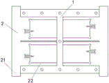
Fig. 1 is the schematic diagram of the structure of the bottom die and the limiting plate of the utility model.
Fig. 2 is an exploded view of fig. 1 according to the present invention.
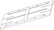
Fig. 3 is a schematic view of the three-dimensional structure of the bottom die of the present invention.
Fig. 4 is a schematic structural view of the back of the bottom die of the present invention.
Fig. 5 is a schematic structural view of the pressing plate of the present invention.
Fig. 6 is a schematic structural view of a pressing plate according to another embodiment of the present invention.
Fig. 7 is a schematic structural diagram of another technical square bump according to the present invention.
In the figure, a bottom die 1, a die area 11, a through hole 12, a limiting plate 2, a pressing plate 3, a limiting fork 21, a lug 22, a bump 23 and a pressing block 4.
Detailed Description
The invention is further elucidated below on the basis of the figures and the embodiments.
The first embodiment.
As shown in fig. 1-3, a vapor chamber welding mould, includes die block 1, limiting plate 2, clamp plate 3, be equipped with a plurality of die zones 11 on the die block 1, die zone 11 is the recess that sinks that sets up on the die block 1 surface, and its height that sinks is greater than the thickness of required welded vapor chamber, 2 thickness of limiting plate slightly less than the height that sinks of die zone 11, 2 front ends of limiting plate are provided with spacing fork 21.
As shown in fig. 4-5, a bump 23 is disposed on the back surface of the bottom mold 1 and the surface of the pressing plate 3, the shape and position of the bump 23 are consistent with the shape defined by the limiting fork 21 and the side wall of the die area 11, and the thickness of the bump 23 is greater than the difference between the sinking height of the die area 11 and the thickness of the uniform temperature plate to be welded.
Example two.
As shown in fig. 1-5, a vapor chamber welding mould, includes die block 1, limiting plate 2, clamp plate 3, be equipped with a plurality of die zones 11 on the die block 1, die zone 11 is the recess that sinks that sets up on the die block 1 surface, and its height that sinks is greater than the thickness of required welded vapor chamber, 2 thickness of limiting plate slightly less than the height that sinks of die zone 11, 2 front ends of limiting plate are provided with spacing fork 21.
As shown in fig. 4-5, a bump 23 is disposed on the back surface of the bottom mold 1 and the surface of the pressing plate 3, the shape and position of the bump 23 are consistent with the shape defined by the limiting fork 21 and the side wall of the die area 11, and the thickness of the bump 23 is greater than the difference between the sinking height of the die area 11 and the thickness of the uniform temperature plate to be welded.
The die is characterized in that a through hole 12 is formed in a position outside a die area 11 of the bottom die 1, and a through hole 12 which is identical to the through hole 12 in position and size on the bottom die 1 is also formed in the plate body of the pressing plate 3. The device also comprises a fastening screw and a fastening nut, wherein the outer diameter of the fastening screw is consistent with the inner diameter of the through hole 12.
Two sides of the outer end of the limiting plate 2 are provided with lugs 22, the outline shape of the limiting fork 21 is consistent with the outline shape of the female die area 11, and the shape defined by the limiting fork 21 and the side wall of the female die area 11 is consistent with the outline shape of the temperature-uniforming plate.
And a temperature equalizing plate air inlet pipe groove is also arranged on the female die area 11.
Example three.
As shown in fig. 1-3, a vapor chamber welding mould, includes die block 1, limiting plate 2, clamp plate 3, be equipped with a plurality of die zones 11 on the die block 1, die zone 11 is the recess that sinks that sets up on the die block 1 surface, and its height that sinks is greater than the thickness of required welded vapor chamber, 2 thickness of limiting plate slightly less than the height that sinks of die zone 11, 2 front ends of limiting plate are provided with spacing fork 21.
As shown in fig. 6-7, in order to further reduce the processing difficulty and prolong the service life, in the present scheme, no convex block is arranged on the back surface of the bottom die 1 and the surface of the pressing plate 3, but a pressing block 4 with a consistent space shape surrounded by the limiting fork 21 and the side wall of the die area 11 is separately manufactured, and the thickness of the pressing block is greater than the difference between the sinking height of the die area 11 and the thickness of the uniform temperature plate to be welded.
Example four.
As shown in fig. 1-3, a vapor chamber welding mould, includes die block 1, limiting plate 2, clamp plate 3, be equipped with a plurality of die zones 11 on the die block 1, die zone 11 is the recess that sinks that sets up on the die block 1 surface, and its height that sinks is greater than the thickness of required welded vapor chamber, 2 thickness of limiting plate slightly less than the height that sinks of die zone 11, 2 front ends of limiting plate are provided with spacing fork 21.
As shown in fig. 6-7, in order to further reduce the processing difficulty and prolong the service life, in the present scheme, no convex block is arranged on the back surface of the bottom die 1 and the surface of the pressing plate 3, but a pressing block 4 with a consistent space shape surrounded by the limiting fork 21 and the side wall of the die area 11 is separately manufactured, and the thickness of the pressing block is greater than the difference between the sinking height of the die area 11 and the thickness of the uniform temperature plate to be welded.
The die is characterized in that a through hole 12 is formed in a position outside a die area 11 of the bottom die 1, and a through hole 12 which is identical to the through hole 12 in position and size on the bottom die 1 is also formed in the plate body of the pressing plate 3. The device also comprises a fastening screw and a fastening nut, wherein the outer diameter of the fastening screw is consistent with the inner diameter of the through hole 12. Two sides of the outer end of the limiting plate 2 are provided with lugs 22, the outline shape of the limiting fork 21 is consistent with the outline shape of the female die area 11, and the shape defined by the limiting fork 21 and the side wall of the female die area 11 is consistent with the outline shape of the temperature-uniforming plate.
Other structures are the same as those of the third embodiment.
Claims (7)
1. The utility model provides a temperature-uniforming plate welding mould, includes die block (1), limiting plate (2), clamp plate (3), its characterized in that: be equipped with a plurality of die areas (11) on die block (1), die area (11) are die block (1) recess that sinks that sets up on the surface, and it sinks highly to be greater than the thickness of required welded samming board, limiting plate (2) thickness slightly is less than the height that sinks of die area (11), and limiting plate (2) front end is provided with spacing fork (21).
2. The welding mold for the temperature equalizing plate as claimed in claim 1, wherein a through hole (12) is formed in a position outside the concave die area (11) of the bottom mold (1), and a through hole (12) having the same position and size as the through hole (12) in the bottom mold (1) is also formed in the plate body of the pressure plate (3).
3. The welding mould for the uniform temperature plate is characterized in that two sides of the outer end of the limiting plate (2) are provided with lugs (22), the outline shape of the limiting fork (21) is consistent with the outline shape of the concave mould area (11), and the shape enclosed by the limiting fork (21) and the side wall of the concave mould area (11) is consistent with the outline shape of the uniform temperature plate.
4. A vapor-proof plate welding mould according to claim 1 or 3, characterized in that a vapor-proof plate air inlet pipe groove is further arranged on the cavity die area (11).
5. The welding mold for vapor-deposition plates according to claim 3, wherein: the back of die block (1) and the surface of clamp plate (3) are provided with lug (23), the shape and the position of lug (23) with spacing fork (21) are unanimous with the shape that die district (11) lateral wall encloses, the thickness of lug (23) is greater than die district (11) and sinks the difference of height and required welded samming thickness.
6. The welding mold for vapor-deposition plates according to claim 3, wherein: the temperature equalizing plate is characterized by further comprising a pressing block (4) which is consistent with the space shape defined by the limiting fork (21) and the side wall of the female die area (11), wherein the thickness of the pressing block is larger than the difference between the sinking height of the female die area (11) and the thickness of the temperature equalizing plate to be welded.
7. The welding mold for vapor-deposition plates according to claim 5 or 6, wherein: the clamping device also comprises a fastening screw and a fastening nut, wherein the outer diameter of the fastening screw is consistent with the inner diameter of the through hole (12).
Priority Applications (1)
| Application Number | Priority Date | Filing Date | Title |
|---|---|---|---|
| CN202020085410.1U CN211638659U (en) | 2020-01-15 | 2020-01-15 | Welding die for temperature-equalizing plate |
Applications Claiming Priority (1)
| Application Number | Priority Date | Filing Date | Title |
|---|---|---|---|
| CN202020085410.1U CN211638659U (en) | 2020-01-15 | 2020-01-15 | Welding die for temperature-equalizing plate |
Publications (1)
| Publication Number | Publication Date |
|---|---|
| CN211638659U true CN211638659U (en) | 2020-10-09 |
Family
ID=72705754
Family Applications (1)
| Application Number | Title | Priority Date | Filing Date |
|---|---|---|---|
| CN202020085410.1U Active CN211638659U (en) | 2020-01-15 | 2020-01-15 | Welding die for temperature-equalizing plate |
Country Status (1)
| Country | Link |
|---|---|
| CN (1) | CN211638659U (en) |
-
2020
- 2020-01-15 CN CN202020085410.1U patent/CN211638659U/en active Active
Similar Documents
| Publication | Publication Date | Title |
|---|---|---|
| CN100491058C (en) | An aluminum alloy air-cooled cold plate sealing forming process | |
| CN114985859B (en) | Production process of stamping type liquid cooling plate | |
| CN102335747B (en) | Preparation method for aluminum silicon carbide compound material IGBT (Insulated Gate Bipolar Translator) substrate and method for inlaying aluminum alloy | |
| CN110966880A (en) | Ultrathin soaking plate and manufacturing method thereof | |
| CN211638658U (en) | High-efficient welding mould of temperature-uniforming plate | |
| CN111069760A (en) | High-efficient welding mould of temperature-uniforming plate | |
| CN212194024U (en) | Injection mold capable of effectively reducing weld lines | |
| TW201910279A (en) | Molded three-dimensional glass mold and mold forming method capable of effectively avoiding the qualitative change of the central portion of the three-dimensional glass after molding, and the curved portion of the middle portion of the molded glass | |
| CN209426080U (en) | A kind of injection mold that silica gel push-button production thermal diffusivity is good | |
| CN211915754U (en) | Novel welding die for uniform temperature plate | |
| CN115283675B (en) | Copper-based friction material sintering process and die | |
| CN116723679A (en) | Ceramic-based vapor chamber and preparation method and application thereof | |
| CN222670788U (en) | High-heat-conductivity integrated part solid temperature equalizing plate | |
| CN212581757U (en) | Long service life's curved graphite jig of 3D glass heat | |
| CN209289697U (en) | A kind of air extractor of flat-panel monitor housing mould | |
| CN116079349A (en) | Connection method of metal substrate and liquid suction core in multidimensional cavity | |
| CN213135530U (en) | High-efficient temperature-uniforming plate welding mould | |
| CN214687102U (en) | Brick pressing die | |
| CN208230772U (en) | A kind of automobile die being equipped with heat sink functionality | |
| CN209381474U (en) | A kind of graphite block forming die | |
| CN218476870U (en) | Mould for producing high-power ceramic radiator | |
| CN212725249U (en) | A sintering mold for SMD-0.5 ceramic paste package products | |
| CN214266332U (en) | Multicolor silica gel mold capable of preventing deformation | |
| CN212266789U (en) | Mold processing device capable of preventing mold deformation | |
| CN210336578U (en) | Sole mould convenient to quick cooling |
Legal Events
| Date | Code | Title | Description |
|---|---|---|---|
| GR01 | Patent grant | ||
| GR01 | Patent grant |