CN211637942U - Punching device for die production - Google Patents
Punching device for die production Download PDFInfo
- Publication number
- CN211637942U CN211637942U CN202020032954.1U CN202020032954U CN211637942U CN 211637942 U CN211637942 U CN 211637942U CN 202020032954 U CN202020032954 U CN 202020032954U CN 211637942 U CN211637942 U CN 211637942U
- Authority
- CN
- China
- Prior art keywords
- punching
- conveying
- collection box
- pipe
- punching device
- Prior art date
- Legal status (The legal status is an assumption and is not a legal conclusion. Google has not performed a legal analysis and makes no representation as to the accuracy of the status listed.)
- Expired - Fee Related
Links
- 238000004080 punching Methods 0.000 title claims abstract description 49
- 238000004519 manufacturing process Methods 0.000 title claims abstract description 14
- 238000011084 recovery Methods 0.000 claims description 14
- 238000005096 rolling process Methods 0.000 claims 1
- 230000000149 penetrating effect Effects 0.000 abstract 1
- 239000002699 waste material Substances 0.000 description 12
- 230000005540 biological transmission Effects 0.000 description 6
- 238000010586 diagram Methods 0.000 description 5
- 239000000463 material Substances 0.000 description 2
- 238000000034 method Methods 0.000 description 2
- 230000009286 beneficial effect Effects 0.000 description 1
- 238000004140 cleaning Methods 0.000 description 1
- 238000010276 construction Methods 0.000 description 1
- 238000000605 extraction Methods 0.000 description 1
- 230000013011 mating Effects 0.000 description 1
- 239000002184 metal Substances 0.000 description 1
- 238000004064 recycling Methods 0.000 description 1
Images


Landscapes
- Punching Or Piercing (AREA)
Abstract
本实用新型属于模具生产技术领域,尤其为一种用于模具生产用冲孔装置,包括箱体,所述箱体的内部开设有回收槽,所述回收槽一端设置有开在所述箱体内部的滑槽,所述收集盒的一侧中心位置焊接有手把,所述收集盒的背面紧密贴合所述支撑架的一侧;两组所述安装架上通过螺栓安装连接有冲压件,所述冲压件的一侧开设的两组卡槽内部分别安装有一组所述安装架,所述卡槽的侧面设置有贯穿所述冲压件的通孔,螺栓贯穿所述通孔安装在所述螺纹孔的内部,所述冲压件的中心位置开设有冲孔槽;根据加工管材模具的尺寸,在确定好管材模具加工的尺寸后,通过对限位环进行旋转,使两组限位环之间的间距吻合管材的宽度尺寸,避免管材进行输送的时候,出现偏移。
The utility model belongs to the technical field of mold production, in particular to a punching device for mold production. Inside the chute, a handle is welded at the center of one side of the collection box, and the back of the collection box is closely attached to one side of the support frame; the two sets of mounting frames are connected with stamping parts by bolts. A set of mounting brackets are respectively installed in the two sets of card slots opened on one side of the stamping part, the sides of the card slots are provided with through holes penetrating the stamping parts, and the bolts are installed in the through holes through the through holes. Inside the threaded hole, a punching groove is opened at the center of the stamping part; according to the size of the pipe mold, after the size of the pipe mold is determined, the limit ring is rotated to make two sets of limit rings. The spacing between them is in line with the width of the pipe to avoid deviation when the pipe is transported.
Description
技术领域:Technical field:
本实用新型涉及模具生产技术领域,具体为一种用于模具生产用冲孔装置。The utility model relates to the technical field of mold production, in particular to a punching device for mold production.
背景技术:Background technique:
模具运用在生活中诸多领域,一些儿童的玩具,橡胶制品的家具用品,或者金属材质的建筑用品,在进行生产的时候,基本上都会使用到模具进行加工,是生产流水线的一部分,模具生产用冲孔装置,通过在特殊的管材上冲压形成通孔,使管材借助这些通孔方便安装固定,而在使用冲孔装置时,需要对管材进行固定,然后在阶段性的进行冲压,现在市场上的冲孔装置有这样的不足:1、输运的时候,管材容易发生偏移;2、对管材进行冲压后,产生的废料不方便进行收集;3、废料收集后,抽出废料时,废料容易散落;4、不方便调节冲压模块的位置,且不方便对模块进行更换;5、运输时,管材容易在输运装置局部停留。Molds are used in many fields of life. Some children's toys, rubber products, furniture, or metal construction supplies are basically used for processing during production. They are part of the production line and are used for mold production. The punching device, by punching through holes on special pipes, makes the pipes easy to install and fix with the help of these through holes. When using the punching device, the pipes need to be fixed, and then punched in stages. Now on the market The punching device has the following shortcomings: 1. During transportation, the pipe is prone to deviation; 2. After the pipe is punched, the waste generated is inconvenient to collect; 3. After the waste is collected, when the waste is drawn out, the waste is easy to Scattered; 4. It is inconvenient to adjust the position of the stamping module, and it is inconvenient to replace the module;
实用新型内容:Utility model content:
为解决上述技术问题,本实用新型一种用于模具生产用冲孔装置,包括:1. 箱体、收集盒、第一输送带和冲压件,所述箱体顶面设有回收槽,回收槽的截面形状为上大下小,所述回收槽一端设有并排的安装架,所述安装架有两个,表面等距设有螺纹孔,所述安装架通过螺栓与螺纹孔连接冲压件,表面中间设有冲孔槽,底面两端设有卡槽,所述冲压件下端两端设有通孔,所述通孔与卡槽在同一中心线,所述回收槽另一端设有收集盒,所述收集盒侧面设有把手,底面设有滑槽,所述滑槽末端设有支撑架,所述箱体顶面两侧设有支架,所述支架顶面设有固定块,所述固定块中间设有冲压机,所述支架后侧设有固定架,所述固定架之间设有滚轴,所述支架前侧设有前固定架,所述前固定架圆周面套设有输送轴,所述输送轴两端设有限位环,所述输送轴一端设有从动齿轮,另一端设有主动齿轮,所述滚轴套设有第一传输带,所述箱体侧面设有挡板,所述挡板表面设有输送电机,所述输送电机侧面转轴套设有连接齿轮,所述连接齿轮与主动齿轮之间通过第二传输带连接。In order to solve the above-mentioned technical problems, the utility model is a punching device for mold production, comprising: 1. a box body, a collection box, a first conveyor belt and a punching part, the top surface of the box body is provided with a recovery groove, and the recovery The cross-sectional shape of the groove is large at the top and small at the bottom. One end of the recovery groove is provided with side-by-side mounting brackets. There are two mounting brackets. The surface is provided with threaded holes at equal distances. The mounting brackets are connected to the stamping parts through bolts and threaded holes. , a punching slot is arranged in the middle of the surface, a clamping slot is arranged at both ends of the bottom surface, a through hole is arranged at both ends of the lower end of the stamping part, the through hole and the clamping slot are on the same centerline, and the other end of the recovery slot is provided with a collecting slot The side of the collection box is provided with a handle, the bottom surface is provided with a chute, the end of the chute is provided with a support frame, the two sides of the top surface of the box are provided with brackets, and the top surface of the bracket is provided with a fixing block, so A punching machine is arranged in the middle of the fixing block, a fixing frame is arranged on the rear side of the bracket, a roller is arranged between the fixing frames, a front fixing frame is arranged on the front side of the bracket, and the circumferential surface of the front fixing frame is sleeved There is a conveying shaft, the two ends of the conveying shaft are provided with limit rings, one end of the conveying shaft is provided with a driven gear, and the other end is provided with a driving gear, the roller sleeve is provided with a first transmission belt, and the side of the box body is provided with a first transmission belt. A baffle is provided, a conveying motor is arranged on the surface of the baffle, a connecting gear is sleeved on the side rotating shaft of the conveying motor, and the connecting gear and the driving gear are connected by a second transmission belt.
进一步技术方案,冲压机的型号为LX001导杆型。As a further technical solution, the model of the punching machine is LX001 guide rod type.
进一步技术方案,输送电机的型号为5IK150RGU-CF。For a further technical solution, the model of the conveying motor is 5IK150RGU-CF.
与现有技术相比,本实用新型的有益效果:1.根据加工管材模具的尺寸,在确定好管材模具加工的尺寸后,通过对限位环进行旋转,使两组限位环之间的间距吻合管材的宽度尺寸,避免管材进行输送的时候,出现偏移。Compared with the prior art, the beneficial effects of the present utility model are as follows: 1. According to the size of the processing pipe mold, after determining the processing size of the pipe mold, the limit ring is rotated to make the space between the two sets of limit rings. The spacing matches the width of the pipe to avoid deviation when the pipe is transported.
2.管材输送到冲压机下方时,冲压机的运作端会下降,控制冲压块冲压管材,配合设置有冲孔槽的冲压件完成对管材的冲孔,冲孔后形成的废料通过回收槽排到收集盒的内部,完成对废料的收集。2. When the pipe is transported to the bottom of the punching machine, the operating end of the punching machine will drop, control the punching block to punch the pipe, cooperate with the punching part with the punching groove to complete the punching of the pipe, and the waste formed after punching will be discharged through the recovery groove. Go to the inside of the collection box to complete the collection of waste.
3.通过手把拉动收集盒,使收集盒通过滑槽中抽出,在抽出的过程中,收集盒的下表面会落到支撑架上,通过支撑架对收集盒进行支撑,使对收集盒进行清理的时候,收集盒内部的废料不会散落。3. Pull the collection box by the handle, so that the collection box can be pulled out through the chute. During the process of pulling out, the lower surface of the collection box will fall on the support frame, and the collection box will be supported by the support frame, so that the collection box can be removed. When cleaning, the waste inside the collection box will not be scattered.
4.根据管材冲压的形状,需要选择对应合适冲孔槽的冲压件,然后将冲压件通过卡槽安装到安装架,然后在安装架上滑动冲压件,调节冲压件的位置,将冲压件调节到合适的位置后,使用螺栓穿过通孔连接到螺纹孔的内部,使冲压件的位置固定,然后将配对的冲压块安装到冲压机运作端。4. According to the shape of the pipe stamping, it is necessary to select the stamping part corresponding to the appropriate punching slot, then install the stamping part to the mounting frame through the slot, and then slide the stamping part on the mounting frame, adjust the position of the stamping part, and adjust the stamping part. Once in place, use bolts through the through holes to connect to the inside of the threaded holes to fix the position of the stamping parts, and then install the mating stamping block to the working end of the stamping machine.
5.使输送电机带动连接齿轮旋转,进而借助第二输送带让主动齿轮旋转,从而控制输送轴旋转,对管材进行输送,每根输送轴上设置的从动齿轮通过第一输送带连接,使每根输送轴均会同步旋转,管材不会再输送机构上停留。5. Make the conveying motor drive the connecting gear to rotate, and then use the second conveying belt to make the driving gear rotate, so as to control the rotation of the conveying shaft and convey the pipes. The driven gear set on each conveying shaft is connected by the first conveying belt, so that the Each conveying shaft will rotate synchronously, and the pipe will not stop on the conveying mechanism.
附图说明:Description of drawings:
附图用来提供对本实用新型进一步理解,并且构成说明书的一部分,与本实用新型的实施例一起用于解释本实用新型,并不构成对本实用新型的限制。在附图中:The accompanying drawings are used to provide a further understanding of the present invention, and constitute a part of the specification. They are used to explain the present invention together with the embodiments of the present invention, and do not constitute a limitation to the present invention. In the attached image:
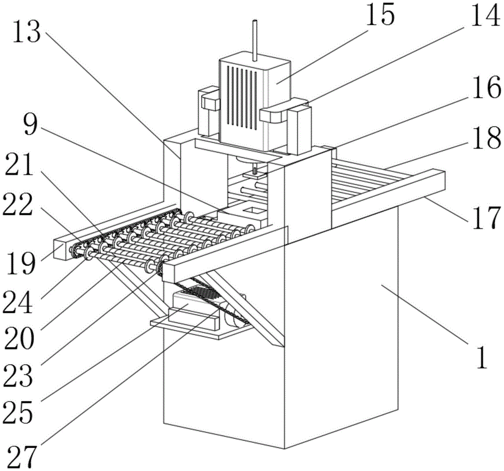
图1为本实用新型正面立体结构示意图;Fig. 1 is the front three-dimensional structure schematic diagram of the utility model;
图2为本实用新型背面立体结构示意图;Figure 2 is a schematic diagram of the back three-dimensional structure of the utility model;
图3为本实用新型剖面结构示意图;Fig. 3 is the cross-sectional structure schematic diagram of the utility model;
图4为本实用新型冲压件结构示意图;Fig. 4 is the structural schematic diagram of the stamping part of the utility model;
图5为本实用新型动力传输机构结构示意图。FIG. 5 is a schematic structural diagram of the power transmission mechanism of the present invention.
附图标记:1、箱体;2、回收槽;3、滑槽;4、支撑架;5、收集盒;6、手把;7、安装架;8、螺纹孔;9、冲压件;10、卡槽;11、通孔;12、冲孔槽;13、支架;14、固定块;15、冲压机;16、冲压块;17、后固定架;18、滚轴; 19、前固定架;20、输送轴;21、从动齿轮;22、第一输送带;23、主动齿轮; 24、限位环;25、输送电机;26、连接齿轮;27、第二输送带。Reference signs: 1. Box body; 2. Recovery slot; 3. Chute; 4. Support frame; 5. Collection box; 6. Handle; 7. Mounting frame; 8. Threaded hole; 9. Stamping part; 10 , card slot; 11, through hole; 12, punching slot; 13, bracket; 14, fixing block; 15, punching machine; 16, punching block; 17, rear fixing frame; 18, roller; 19,
具体实施方式:Detailed ways:
如图所示,一种用于模具生产用冲孔装置,包括:箱体1、收集盒5、第一输送带22和冲压件9,所述箱体1为长方形,顶面设有回收槽2,回收槽2的截面形状为上大下小,所述回收槽2一端设有并排的安装架7,所述安装架7有两个,表面等距设有螺纹孔8,所述安装架7通过螺栓与螺纹孔8连接冲压件9,所述冲压件9下端宽度大于上端宽度,表面中间设有冲孔槽12,底面两端设有卡槽10,所述冲压件9下端两端设有通孔11,所述通孔11与卡槽10在同一中心线,所述回收槽2另一端设有收集盒5,所述收集盒5侧面设有把手6,底面设有滑槽3,所述滑槽3末端设有支撑架4,所述滑槽3与收集盒5滑动连接,所述收集盒5滑出滑槽3,所述支撑架4在收集盒5底面,所述箱体1顶面两侧设有支架13,所述支架13顶面设有固定块14,所述固定块中间设有冲压机15,冲压机15的型号为LX001导杆型,所述冲压机15的运作端安装有符合冲孔槽 12形状的冲压块16,所述支架13后侧设有固定架17,所述固定架17之间设有滚轴18,所述支架13前侧设有前固定架19,所述前固定架19圆周面套设有输送轴20,所述输送轴20两端设有限位环24,所述输送轴20一端设有从动齿轮 21,另一端设有主动齿轮23,所述滚轴18套设有第一传输带22,所述箱体1 侧面设有挡板,所述挡板表面设有输送电机25,输送电机25的型号为 5IK150RGU-CF,所述输送电机侧面转轴套设有连接齿轮26,所述连接齿轮26与主动齿轮23之间通过第二传输带27连接。As shown in the figure, a punching device for mold production includes: a
工作原理:在使用该用于模具生产用冲孔装置时,首先,根据管材冲压的形状,需要选择对应合适冲孔槽12的冲压件9,然后将冲压件9通过卡槽10安装到安装架7,然后在安装架7上滑动冲压件9,调节冲压件9的位置,将冲压件 9调节到合适的位置后,使用螺栓穿过通孔11连接到螺纹孔8的内部,使冲压件9的位置固定,然后将配对的冲压块16安装到冲压机15运作端,再根据加工管材模具的尺寸,在确定好管材模具加工的尺寸后,通过对限位环24进行旋转,使两组限位环24之间的间距吻合管材的宽度尺寸,避免管材进行输送的时候,出现偏移,然后将需要将加工的管材模具放置到输送轴20上,连接电源,启动输送电机25,使输送电机25带动连接齿轮26旋转,进而借助第二输送带27让主动齿轮23旋转,从而控制输送轴20旋转,对管材进行输送,将管材输送到冲压机15下方时,冲压机15的运作端会下降,控制冲压块16冲压管材,配合设置有冲孔槽12的冲压件9完成对管材的冲孔,通过输送轴20继续对管材进行输送,使管材通过滚轴18排出,完成对管材模具的冲孔,冲孔后形成的废料通过回收槽2排到收集盒5的内部,完成对废料的收集,当经过一段时间的加工后,收集盒5收集足够多的废料后,需要对这些废料进行收集,通过手把6拉动收集盒5,使收集盒5通过滑槽3中抽出,在抽出的过程中,收集盒5的下表面会落到支撑架4上,通过支撑架4对收集盒5进行支撑,使对收集盒5进行清理的时候,收集盒5内部的废料不会散落。Working principle: When using the punching device for die production, first, according to the shape of the pipe punching, it is necessary to select the punching
本实用新型方案所公开的技术手段不仅限于上述技术手段所公开的技术手段,还包括由以上技术特征等同替换所组成的技术方案。本实用新型的未尽事宜,属于本领域技术人员的公知常识。The technical means disclosed by the solution of the present invention are not limited to the technical means disclosed by the above-mentioned technical means, but also include the technical solutions formed by the equivalent replacement of the above-mentioned technical features. The unresolved matters of the present invention belong to the common knowledge of those skilled in the art.
Claims (3)
Priority Applications (1)
| Application Number | Priority Date | Filing Date | Title |
|---|---|---|---|
| CN202020032954.1U CN211637942U (en) | 2020-01-08 | 2020-01-08 | Punching device for die production |
Applications Claiming Priority (1)
| Application Number | Priority Date | Filing Date | Title |
|---|---|---|---|
| CN202020032954.1U CN211637942U (en) | 2020-01-08 | 2020-01-08 | Punching device for die production |
Publications (1)
| Publication Number | Publication Date |
|---|---|
| CN211637942U true CN211637942U (en) | 2020-10-09 |
Family
ID=72704093
Family Applications (1)
| Application Number | Title | Priority Date | Filing Date |
|---|---|---|---|
| CN202020032954.1U Expired - Fee Related CN211637942U (en) | 2020-01-08 | 2020-01-08 | Punching device for die production |
Country Status (1)
| Country | Link |
|---|---|
| CN (1) | CN211637942U (en) |
Cited By (1)
| Publication number | Priority date | Publication date | Assignee | Title |
|---|---|---|---|---|
| CN111097833A (en) * | 2020-01-08 | 2020-05-05 | 南京工业职业技术学院 | A punching device for mold production |
-
2020
- 2020-01-08 CN CN202020032954.1U patent/CN211637942U/en not_active Expired - Fee Related
Cited By (1)
| Publication number | Priority date | Publication date | Assignee | Title |
|---|---|---|---|---|
| CN111097833A (en) * | 2020-01-08 | 2020-05-05 | 南京工业职业技术学院 | A punching device for mold production |
Similar Documents
| Publication | Publication Date | Title |
|---|---|---|
| CN104429623B (en) | Solid spawn Inoculation machine Jun Bao spike pulling mechanism | |
| CN104192566B (en) | Fowl egg processing sucker automatic charging device | |
| CN208744136U (en) | A kind of continuously shaped mold of shearing bending | |
| CN110948856A (en) | Raw material recovery processing device for 3D metal printer | |
| CN111097833A (en) | A punching device for mold production | |
| CN222326512U (en) | Waste collection device for punching and shearing machine | |
| CN204426070U (en) | Solid spawn Inoculation machine Jun Bao spike pulling mechanism | |
| CN216153154U (en) | Full-automatic flat-pressing flat die cutting machine | |
| CN215665652U (en) | Roller type low-resistance feeding machine | |
| CN211840852U (en) | A former for producing push-pull valve | |
| CN113734695B (en) | Incomplete face recovery plant based on environmental protection and energy saving | |
| CN205650590U (en) | Old and useless panel face clearance production line | |
| CN212069154U (en) | A kind of electrolytic zinc solid waste sorting device | |
| CN202766285U (en) | Novel dust-collection cotton fluffer | |
| CN207789944U (en) | A kind of air duct plain cloth machine | |
| CN205395124U (en) | Special vacuum plastic former of degradation material | |
| CN223396484U (en) | Automatic material collecting device with counting function | |
| CN221234709U (en) | A separation device for fabric recycling | |
| CN112794025A (en) | A roller type low-resistance feeder | |
| CN218224186U (en) | Bearing plate oil cavity grooving machine | |
| CN215824185U (en) | Conveyor belt oil receiving mechanism for cold header | |
| CN222929208U (en) | Soybean peeling device for producing soybean milk powder | |
| CN221515262U (en) | Stamping part sorting device | |
| CN214022913U (en) | Motor accessories punching tooling | |
| CN221575699U (en) | A PCB circuit board production mold |
Legal Events
| Date | Code | Title | Description |
|---|---|---|---|
| GR01 | Patent grant | ||
| GR01 | Patent grant | ||
| CF01 | Termination of patent right due to non-payment of annual fee |
Granted publication date: 20201009 |
|
| CF01 | Termination of patent right due to non-payment of annual fee |