CN211621459U - Slope protection device convenient to install and used for water conservancy and hydropower construction - Google Patents
Slope protection device convenient to install and used for water conservancy and hydropower construction Download PDFInfo
- Publication number
- CN211621459U CN211621459U CN201922403507.2U CN201922403507U CN211621459U CN 211621459 U CN211621459 U CN 211621459U CN 201922403507 U CN201922403507 U CN 201922403507U CN 211621459 U CN211621459 U CN 211621459U
- Authority
- CN
- China
- Prior art keywords
- box body
- water
- water conservancy
- seted
- water hole
- Prior art date
- Legal status (The legal status is an assumption and is not a legal conclusion. Google has not performed a legal analysis and makes no representation as to the accuracy of the status listed.)
- Expired - Fee Related
Links
- XLYOFNOQVPJJNP-UHFFFAOYSA-N water Substances O XLYOFNOQVPJJNP-UHFFFAOYSA-N 0.000 title claims abstract description 52
- 238000010276 construction Methods 0.000 title claims abstract description 19
- 238000009434 installation Methods 0.000 claims abstract description 11
- 230000001012 protector Effects 0.000 claims abstract description 7
- 230000000149 penetrating effect Effects 0.000 claims abstract description 4
- 230000005611 electricity Effects 0.000 abstract description 4
- 238000000034 method Methods 0.000 abstract description 2
- 230000000694 effects Effects 0.000 description 5
- 230000006378 damage Effects 0.000 description 4
- 208000027418 Wounds and injury Diseases 0.000 description 2
- 230000000903 blocking effect Effects 0.000 description 2
- 230000005484 gravity Effects 0.000 description 2
- 208000014674 injury Diseases 0.000 description 2
- 238000013508 migration Methods 0.000 description 2
- 230000005012 migration Effects 0.000 description 2
- 230000001681 protective effect Effects 0.000 description 2
- 239000002689 soil Substances 0.000 description 2
- 239000007787 solid Substances 0.000 description 2
- 206010063659 Aversion Diseases 0.000 description 1
- 238000006424 Flood reaction Methods 0.000 description 1
- 230000007547 defect Effects 0.000 description 1
- 238000010586 diagram Methods 0.000 description 1
- 238000003780 insertion Methods 0.000 description 1
- 230000037431 insertion Effects 0.000 description 1
- 238000012986 modification Methods 0.000 description 1
- 230000004048 modification Effects 0.000 description 1
- 238000009991 scouring Methods 0.000 description 1
- 238000006467 substitution reaction Methods 0.000 description 1
- 238000012876 topography Methods 0.000 description 1
Images

Landscapes
- Revetment (AREA)
Abstract
The utility model provides a slope protector for water conservancy water and electricity construction convenient to installation, includes preceding open-ended box body, and several rows of through-holes are seted up at the back of box body, are equipped with the baffle in the box body, and the penetrating first water hole of several is seted up to the top surface of baffle, and the communicating second water hole of inside with it is seted up to the bottom surface of box body, and the diameter in second water hole is greater than first water hole, the equal fixed mounting opening in both sides of box body frid and inserted block forward. The utility model discloses during the installation, make the front of box body be higher than the river slope 3-5 CM, when two adjacent box bodies of same row were installed, make the inserted block of the opposite face of two box bodies insert respectively to the frid that corresponds in, leave 1-2 CM's clearance between frid and another box body, the box body of two adjacent rows makes the joint line stagger as far as possible when placing. During field construction, only the box bodies are spliced, and the method is very convenient.
Description
Technical Field
The utility model belongs to side slope protection field, specifically speaking are side slope protector for water conservancy and hydropower construction convenient to installation.
Background
Slope protection refers to the general term of various paving and planting on a slope surface in order to prevent the slope from being washed. In the river section where the bridge site is located, the concave bank of the river bank is washed by water flow year by year, and the river bank can be continuously collapsed. In order to protect the safety of bridges and embankments, protective buildings need to be built on the concave bank. In addition, when the river flow direction changes due to the arrangement of bridges and the farmland and villages are endangered by scouring the river bank, protective buildings need to be built on the river bank. In the current side slope protection device, due to the topography problem, the acting force of flowing water on the river bank is not uniform, and after a long time, the side slope at a certain section is easy to settle or shift, so that the side slope connected with the side slope is also changed, and the protection effect of the side slope is reduced.
SUMMERY OF THE UTILITY MODEL
The utility model provides a water conservancy is side slope protector for water and electricity construction convenient to installation for solve the defect among the prior art.
The utility model discloses a following technical scheme realizes:
the utility model provides a slope protector for water conservancy water and electricity construction convenient to installation, includes preceding open-ended box body, and several rows of through-holes are seted up at the back of box body, are equipped with the baffle in the box body, and the penetrating first water hole of several is seted up to the top surface of baffle, and the communicating second water hole of inside with it is seted up to the bottom surface of box body, and the diameter in second water hole is greater than first water hole, the equal fixed mounting opening in both sides of box body frid and inserted block forward.
As the slope protection device convenient to install for water conservancy and hydropower construction, the baffle is of an arc structure with a downward concave surface.
According to the slope protection device convenient to install for water conservancy and hydropower construction, the groove plates and the inserting blocks on the two sides of the box body are arranged in a staggered mode.
As the slope protection device convenient to install for water conservancy and hydropower construction, through nail holes are formed in four front corners of the box body, and the nail columns are movably installed in the nail holes.
A side slope protector for water conservancy and hydropower construction convenient to installation as above, the inner wall in nail hole all set up several bar groove, both ends all communicate with each other with the external world around the bar groove, the equal fixed mounting several rows of wedge pieces in periphery of nail post, the wedge piece homoenergetic passes the bar groove.
The utility model has the advantages that: the utility model discloses during the installation, make the front of box body be higher than the river slope 3-5 CM, when two adjacent box bodies of same row were installed, make the inserted block of the opposite face of two box bodies insert respectively to the frid that corresponds in, leave 1-2 CM's clearance between frid and another box body, the box body of two adjacent rows makes the joint line stagger as far as possible when placing. During field construction, only the box bodies are spliced, and the method is very convenient. The utility model discloses adorn in river levee department, the rainwater that can prevent the gathering in rainy season erodees the river levee, the top surface of the box body of eminence river levee at first can block the rainwater, fall into it behind the top surface of top box body when the rainwater floods, the plant of planting has solid soil effect in the box body, avoid causing the injury to the river levee when can absorbing the rainwater, when unnecessary rainwater flows downwards, the baffle can play the effect of blocking water equally, so reduce the velocity of flow of rainwater layer upon layer, in order to reduce its damage to the dyke, the same reason when flood season, when river upwards strikes, can consume its kinetic energy, the inserted block can be in frid inner horizontal migration, roughly comply with river water to, the micro-deformation of adaptable dyke, the overall structure and the function that can guarantee the bank protection simultaneously are not influenced.
Drawings
In order to more clearly illustrate the embodiments of the present invention or the technical solutions in the prior art, the drawings needed to be used in the description of the embodiments or the prior art will be briefly described below, and it is obvious that the drawings in the following description are some embodiments of the present invention, and for those skilled in the art, other drawings can be obtained according to these drawings without inventive labor.
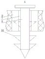
Fig. 1 is a schematic structural diagram of the present invention; fig. 2 is an enlarged view of the view from the direction a of fig. 1.
Detailed Description
In order to make the objects, technical solutions and advantages of the embodiments of the present invention clearer, the embodiments of the present invention will be clearly and completely described below with reference to the accompanying drawings in the embodiments of the present invention, and it is obvious that the described embodiments are some, but not all, embodiments of the present invention. Based on the embodiments in the present invention, all other embodiments obtained by a person skilled in the art without creative efforts belong to the protection scope of the present invention.
The utility model provides a side slope protector is used in water conservancy water and electricity construction convenient to installation, as shown in the figure, including preceding open-ended box body 1, the longitudinal length of box body 1 is 12-15 CM, several rows of through-holes 11 are seted up to the back of box body 1, be equipped with baffle 2 in planting slope protection plant box body 1, the equal fixed connection box body's in both sides inner wall both sides of baffle 2, the penetrating first water hole 3 of several is seted up to the top surface of baffle 2, communicating second water hole 4 of inside with it is seted up to the bottom surface of box body 1, the diameter in second water hole 4 is greater than first water hole 3, second water hole 4 and 3 staggered arrangement in first water hole, the equal fixed mounting opening of both sides of box body 1 is slotted plate 5 and inserted block 6 forward, the length of slotted plate 5 is 8-10 CM, the cross-section of slotted. The utility model discloses during the installation, make the front of box body 1 be higher than the river slope 3-5 CM, when two adjacent box bodies 1 of same row were installed, make the inserted block 6 of the opposite face of two box bodies 1 insert respectively to corresponding frid 5 in, leave 1-2 CM's clearance between frid 5 and another box body 1, two adjacent rows of box bodies 1 make the joint line stagger when placing as far as possible. During field construction, only the box body 1 is spliced, which is very convenient. The utility model discloses adorn in river levee department, the rainwater that can prevent the gathering in rainy season erodees the river levee, the top surface of box body 1 of eminence river levee at first can block the rainwater, fall into it behind the top surface of top box body 1 when the rainwater is walked, the plant of planting has solid soil effect in the box body 1, avoid causing the injury to the river levee when can absorbing the rainwater, when unnecessary rainwater flows downwards, baffle 2 equally can play the effect of blocking water, so reduce the velocity of flow of rainwater layer upon layer, in order to reduce its damage to the embankment, arrange when the flood season, river water is when upwards assaulting, can consume its kinetic energy, inserted block 6 can be in 5 interior horizontal migration of frid, roughly comply with river rivers to, the micro-deformation of adaptable embankment, the overall structure and the function that can guarantee the bank protection simultaneously are.
Specifically, as shown in fig. 1, the baffle 2 of the present embodiment has an arc structure with a downward concave surface. If the bright water in the box body 1 is too much, when the bright water flows downwards along the slope, the arc-shaped structure can disperse the bright water along the surface of the bright water to two sides, so that the flow velocity of the bright water is effectively reduced, the surplus water can be prevented from being left in the box body 1, the excited water flows to the concave surface to impact in the flood season, and the structure can buffer a small part of kinetic energy of the water flow.
Specifically, as shown in fig. 1, the slot plates 5 and the insertion blocks 6 on two sides of the box body 1 according to the embodiment are arranged in a staggered manner. This structure enables the center of gravity of the case 1 to be located at the middle thereof, so that the shift of the center of gravity does not cause the shift of the position of the case 1.
Further, as shown in fig. 1, transparent nail holes 7 are formed in four corners of the front surface of the box body 1, a nail column 8 is movably mounted in the nail holes 7, the nail column 8 is of a T-shaped structure, and the diameter of the blunt end of the nail column is larger than that of the nail holes 7. The periphery of post 8 and the inner wall contact cooperation of nail hole 7 and can follow it and slide, and during the installation, the workman passes post 8 and pounces into the river bank behind the nail hole 7 in, can strengthen this device and the connection tightness of river bank, can further reduce the possibility of aversion.
Furthermore, as shown in fig. 2, a plurality of strip-shaped grooves 9 are formed in the inner wall of the nail hole 7 in the embodiment, the front end and the rear end of each strip-shaped groove 9 are communicated with the outside, a plurality of rows of wedge-shaped pieces 10 are fixedly mounted on the periphery of each nail column 8, the wedge-shaped pieces 10 arranged on the periphery of each nail column 8 are not more than three rows, so that the river bank is prevented from being damaged excessively, and the wedge-shaped pieces 10 can penetrate through the strip-shaped grooves 9. After the nail column 8 is hammered into the river bank, the contact surface between the wedge-shaped piece 10 and the river bank is increased, the possibility that the nail column 8 is shaken by impact can be reduced, and the stability of the box body 1 can be further improved.
Finally, it should be noted that: the above embodiments are only used to illustrate the technical solution of the present invention, and not to limit it; although the present invention has been described in detail with reference to the foregoing embodiments, it should be understood by those skilled in the art that: the technical solutions described in the foregoing embodiments may still be modified, or some technical features may be equivalently replaced; such modifications and substitutions do not depart from the spirit and scope of the present invention in its corresponding aspects.
Claims (5)
1. The utility model provides a side slope protector for water conservancy and hydropower construction convenient to installation, includes preceding open-ended box body (1), and several rows of through-holes (11), its characterized in that are seted up to the back of box body (1): be equipped with baffle (2) in box body (1), the penetrating first water hole of several (3) is seted up to the top surface of baffle (2), and communicating second water hole (4) of inside with it is seted up to the bottom surface of box body (1), and the diameter in second water hole (4) is greater than first water hole (3), equal fixed mounting opening forward frid (5) and inserted block (6) in both sides of box body (1).
2. The slope protection device convenient to install for water conservancy and hydropower construction of claim 1, characterized in that: the baffle (2) is of an arc structure with a downward concave surface.
3. The slope protection device convenient to install for water conservancy and hydropower construction of claim 1, characterized in that: the groove plates (5) and the inserting blocks (6) on the two sides of the box body (1) are arranged in a staggered mode.
4. A slope protection device for water conservancy and hydropower construction convenient to install according to claim 1, 2 or 3, characterized in that: transparent nail holes (7) are formed in four corners of the front surface of the box body (1), and nail columns (8) are movably mounted in the nail holes (7).
5. The slope protection device convenient to install for water conservancy and hydropower construction of claim 4, characterized in that: the inner wall of nail hole (7) all set up several bar groove (9), both ends all communicate with each other with the external world around bar groove (9), the equal fixed mounting of the periphery of nail post (8) several rows of wedge pieces (10), the bar groove (9) can be passed in wedge piece (10) homoenergetic.
Priority Applications (1)
| Application Number | Priority Date | Filing Date | Title |
|---|---|---|---|
| CN201922403507.2U CN211621459U (en) | 2019-12-27 | 2019-12-27 | Slope protection device convenient to install and used for water conservancy and hydropower construction |
Applications Claiming Priority (1)
| Application Number | Priority Date | Filing Date | Title |
|---|---|---|---|
| CN201922403507.2U CN211621459U (en) | 2019-12-27 | 2019-12-27 | Slope protection device convenient to install and used for water conservancy and hydropower construction |
Publications (1)
| Publication Number | Publication Date |
|---|---|
| CN211621459U true CN211621459U (en) | 2020-10-02 |
Family
ID=72632852
Family Applications (1)
| Application Number | Title | Priority Date | Filing Date |
|---|---|---|---|
| CN201922403507.2U Expired - Fee Related CN211621459U (en) | 2019-12-27 | 2019-12-27 | Slope protection device convenient to install and used for water conservancy and hydropower construction |
Country Status (1)
| Country | Link |
|---|---|
| CN (1) | CN211621459U (en) |
-
2019
- 2019-12-27 CN CN201922403507.2U patent/CN211621459U/en not_active Expired - Fee Related
Similar Documents
| Publication | Publication Date | Title |
|---|---|---|
| US11155973B1 (en) | Triangular modular ecological seawall | |
| CN216864997U (en) | Multistage unrestrained seawall structure that disappears | |
| CN209353303U (en) | A kind of specific structure that dissipation and scouring is reinforced | |
| CN209053072U (en) | A kind of arch dam Spillway stream energy-dissipating structure | |
| CN215925856U (en) | A differential protection device for breaking waves and fixing embankments | |
| CN213740864U (en) | Anti-skidding slope protection structure for hydraulic engineering | |
| CN212026132U (en) | Hydraulic engineering protection buffering slope | |
| CN222730463U (en) | An ecological riverbank structure | |
| CN210561974U (en) | Multifunctional seawall system | |
| CN221741186U (en) | Energy dissipation and anti-collision device | |
| CN221072461U (en) | Assembled layering spur dike | |
| CN210002343U (en) | Combined overflow dam structure | |
| CN219825107U (en) | Soil and water conservation slope protection brick with deceleration effect | |
| CN222120267U (en) | A rock and soil slope protection structure | |
| CN221778422U (en) | A reinforcement structure for earth-rock dam | |
| CN222227194U (en) | Three-dimensional ecological slope protection structure of scour prevention | |
| CN223176652U (en) | Wave-eliminating stepped ecological bank protection structure for inland river bank protection engineering | |
| CN219772912U (en) | Reservoir spillway reinforced structure | |
| CN221193195U (en) | Assembled ecological road component for river beach road | |
| CN217781894U (en) | Be applied to hydraulic engineering's reinforcement afforestation dykes and dams | |
| CN221855403U (en) | Scour-preventing river bank protection structure | |
| CN221218695U (en) | River course flood control slope protection structure | |
| CN222390369U (en) | Ecological bank protection structure | |
| CN204401567U (en) | Device for preventing stone from entering tail canal of factory building | |
| CN218757253U (en) | Water conservancy bank protection |
Legal Events
| Date | Code | Title | Description |
|---|---|---|---|
| GR01 | Patent grant | ||
| GR01 | Patent grant | ||
| CF01 | Termination of patent right due to non-payment of annual fee | ||
| CF01 | Termination of patent right due to non-payment of annual fee |
Granted publication date: 20201002 |