CN211618189U - Turret Type Taping Machine Turntable Press Down Structure - Google Patents
Turret Type Taping Machine Turntable Press Down Structure Download PDFInfo
- Publication number
- CN211618189U CN211618189U CN201922462207.1U CN201922462207U CN211618189U CN 211618189 U CN211618189 U CN 211618189U CN 201922462207 U CN201922462207 U CN 201922462207U CN 211618189 U CN211618189 U CN 211618189U
- Authority
- CN
- China
- Prior art keywords
- pressing
- lower pressing
- connecting rod
- assembly
- rod
- Prior art date
- Legal status (The legal status is an assumption and is not a legal conclusion. Google has not performed a legal analysis and makes no representation as to the accuracy of the status listed.)
- Active
Links
Images


Landscapes
- Manipulator (AREA)
Abstract
一种转塔式编带机转盘下压结构,包括支撑臂、安装底板、动力源、连杆组件,以及下压板组件,所述安装底板安装在所述支撑臂上,所述动力源安装在所述安装底板上,所述连杆组件用于连接动力源与下压板组件,所述动力源用于驱动所述连杆组件动作,从而带动所述下压板组件进行下压或上升的动作。本实用新型具有结构更加简单、更加方便拆装调试的、成本更低的、占用空间也更小的优点。
A turret type tape braiding machine turntable pressing structure, comprising a support arm, an installation base plate, a power source, a connecting rod assembly, and a lower pressure plate assembly, the installation base plate is installed on the support arm, and the power source is installed on the On the installation bottom plate, the connecting rod assembly is used to connect the power source and the lower pressing plate assembly, and the power source is used to drive the action of the connecting rod assembly, so as to drive the lower pressing plate assembly to perform a downward pressing or rising action. The utility model has the advantages of simpler structure, more convenient disassembly, assembly and debugging, lower cost and smaller occupied space.
Description
技术领域technical field
本实用新型涉及编带机领域,尤其涉及一种转塔式编带机转盘下压结构。The utility model relates to the field of tape braiding machines, in particular to a turntable pressing down structure of a turret type tape braiding machine.
背景技术Background technique
目前,市场上的转塔式编带机中的转盘下压结构主要有两种,一种采用直线电机驱动下压环,下压环连接下压杆推动吸嘴从而实现下压动作,另一种则是采用在吸嘴上方安装独立的电机,通过在电机轴上安装的凸轮和下压杆上的凸轮轴承随动器相切,弹簧回程的方式来实现吸嘴的下压动作。At present, there are mainly two types of turntable pressing structures in the turret type taping machine on the market. One uses a linear motor to drive the pressing ring, and the lower pressing ring is connected to the pressing rod to push the suction nozzle to realize the pressing action. The other is to install an independent motor above the suction nozzle, and realize the downward pressing action of the suction nozzle through the tangent tangent between the cam installed on the motor shaft and the cam bearing follower on the lower pressure rod, and the spring return.
但是,上述的两种实现转盘下压的结构方式,在使用的过程中,主要存在下述缺陷;第一,直线电机驱动下压的方式,所使用的直线电机价格昂贵,成本高,拆装更换维修麻烦,且上下活动的过程中的产生的各种力直接作用到电机上,易造成直线电机的磨损。However, the above two structural methods for realizing the pressing down of the turntable mainly have the following defects in the process of use. First, the linear motor drives the pressing down method, and the linear motor used is expensive, high cost, disassembly and assembly. It is troublesome to replace and maintain, and various forces generated in the process of up and down movement directly act on the motor, which is easy to cause wear of the linear motor.
第二,独立电机驱动凸轮挤压凸轮随动器下压的方式,需要多组电机驱动,不仅成本高,而且占用面积大,凸轮与凸轮随动器相切,在启动的瞬间需要较大扭力,且容易磨损。Second, the independent motor-driven cam squeezes the cam follower to press down, which requires multiple sets of motors to drive, which is not only expensive, but also occupies a large area. The cam is tangent to the cam follower, which requires a large torque at the moment of startup. , and easy to wear.
实用新型内容Utility model content
为了解决上述问题,本实用新型向社会提供一种成本更低的、拆装更加方便的转塔式编带机转盘下压结构。In order to solve the above problems, the utility model provides the society with a lower-cost, more convenient disassembly and assembly of the turntable pressing down structure of the turret type tape braiding machine.
本实用新型的技术方案是:提供一种转塔式编带机转盘下压结构,包括支撑臂、安装底板、动力源、连杆组件,以及下压板组件,所述安装底板安装在所述支撑臂上,所述动力源安装在所述安装底板上,所述连杆组件用于连接动力源与下压板组件,所述动力源用于驱动所述连杆组件动作,从而带动所述下压板组件进行下压或上升的动作。The technical scheme of the utility model is to provide a turntable pressing structure of a turret type tape braiding machine, which includes a support arm, an installation base plate, a power source, a connecting rod assembly, and a lower pressure plate assembly, and the installation base plate is installed on the support On the arm, the power source is installed on the installation bottom plate, the connecting rod assembly is used to connect the power source and the lower pressing plate assembly, and the power source is used to drive the action of the connecting rod assembly to drive the lower pressing plate The components are pressed down or up.
作为本实用新型的改进,所述连杆组件包括第一连杆、第一凸轮随动器、第二连杆,以及第二凸轮随动器,所述第一连杆一端与动力源的轴端连接,另一端通过第一凸轮随动器与所述第二连杆连接,所述第二连杆还通过所述第二凸轮随动器与所述下压板组件连接,驱动动力源,在连杆组件的作用下,所述下压板组件作下压或上升运动。As an improvement of the present invention, the connecting rod assembly includes a first connecting rod, a first cam follower, a second connecting rod, and a second cam follower. One end of the first connecting rod is connected to the shaft of the power source. The second connecting rod is connected with the second connecting rod through the first cam follower, and the second connecting rod is also connected with the lower pressing plate assembly through the second cam follower to drive the power source. Under the action of the connecting rod assembly, the lower pressing plate assembly moves downward or upward.
作为本实用新型的改进,所述下压板组件包括下压板、至少两个下压臂,以及下压环,所述下压臂安装在所述下压板的两侧,所述下压环安装在所述下压臂的底部。As an improvement of the present invention, the lower pressing plate assembly includes a lower pressing plate, at least two lower pressing arms, and a lower pressing ring, the lower pressing arms are installed on both sides of the lower pressing plate, and the lower pressing ring is installed on the lower pressing plate. the bottom of the lower arm.
作为本实用新型的改进,还包括导轨和滑块,所述导轨安装在所述安装底板上,所述滑块安装在所述下压板上,所述滑块与所述导轨配合,且所述滑块可在所述导轨上滑动。As an improvement of the present invention, it also includes a guide rail and a sliding block, the guide rail is installed on the installation bottom plate, the sliding block is installed on the lower pressing plate, the sliding block is matched with the guide rail, and the The slider can slide on the guide rail.
作为本实用新型的改进,还包括下压杆、滚珠衬套和弹簧,所述滚珠衬套和弹簧依次套设在所述下压杆上,所述下压杆的滚珠衬套所在的一端固定在所述下压环上。As an improvement of the present utility model, it also includes a lower pressure rod, a ball bushing and a spring, the ball bushing and the spring are sequentially sleeved on the lower pressure rod, and the end of the lower pressure rod where the ball bushing is located is fixed on the push-down ring.
作为本实用新型的改进,还包括下压杆调节块和导向杆,所述下压杆调节块安装在下压杆的上端,所述导向杆安装在所述下压环上。As an improvement of the present invention, it also includes a lower pressure rod adjusting block and a guide rod, the lower pressure rod adjustment block is installed on the upper end of the lower pressure rod, and the guide rod is installed on the lower pressure ring.
作为本实用新型的改进,还包括安装在安装底板上的光电安装杆和光电安装环和光电开关,所述光电开关可与感应片配合从而实现检测。As an improvement of the utility model, it also includes a photoelectric installation rod, a photoelectric installation ring and a photoelectric switch installed on the installation base plate, and the photoelectric switch can cooperate with the induction sheet to realize detection.
本实用新型由于包括支撑臂、安装底板、动力源、连杆组件,以及下压板组件,所述安装底板安装在所述支撑臂上,所述动力源安装在所述安装底板上,所述连杆组件用于连接动力源与下压板组件,所述动力源用于驱动所述连杆组件动作,从而带动所述下压板组件进行下压或上升的动作。本实用新型在使用时,驱动所述动力源,在所述连杆组件的作用下,从而可以带动所述下压板组件实现下压或者上升动作,本实用新型通过连杆组件,将动力源的轴转动动作转换为下压板组件的上述或者下压动作,本实用新型相对于现有技术而言,结构容易拆装调试,而且成本低,占用空间也小,因此,本实用新型具有结构更加简单、更加方便拆装调试的、成本更低的、占用空间也更小的优点。The utility model includes a support arm, an installation base plate, a power source, a connecting rod assembly, and a lower pressing plate assembly, the installation base plate is installed on the support arm, the power source is installed on the installation base plate, and the connection The rod assembly is used for connecting the power source and the lower pressing plate assembly, and the power source is used for driving the action of the connecting rod assembly, so as to drive the lower pressing plate assembly to perform the action of pressing down or rising. When the utility model is in use, the power source is driven, and under the action of the connecting rod assembly, the lower pressing plate assembly can be driven to realize the pressing or rising action. Compared with the prior art, the structure of the present utility model is easy to disassemble, assemble and debug, and the cost is low, and the occupied space is also small. Therefore, the present utility model has a simpler structure. , The advantages of more convenient disassembly and debugging, lower cost and smaller space occupation.
附图说明Description of drawings
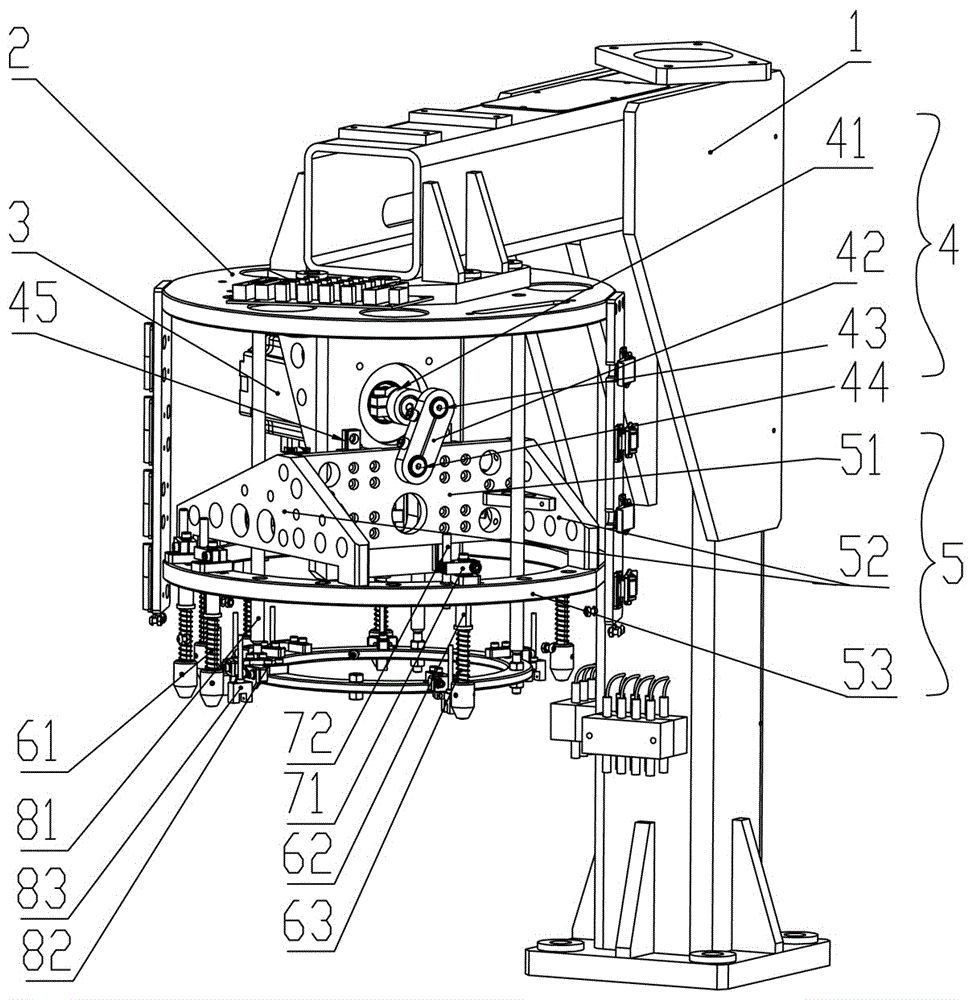
图1是本实用新型的一种实施例的拆开护罩后的立体结构示意图。FIG. 1 is a schematic three-dimensional structure diagram of an embodiment of the present invention after disassembling the protective cover.
图2是图1装上护罩后的结立体构示意图。FIG. 2 is a schematic diagram of the structure of FIG. 1 after the protective cover is installed.
图3是图1中的下压环。FIG. 3 is the lower pressing ring in FIG. 1 .
具体实施方式Detailed ways
请参见图1至图3,图1至图3揭示的是转塔式编带机转盘下压结构的一种实施方式,一种转塔式编带机转盘下压结构,包括支撑臂1、安装底板2、动力源3、连杆组件4,以及下压板组件5,所述安装底板2安装在所述支撑臂1上,本实施例中,所述支撑臂1为带横杆和竖杆的“7”字形,所述安装底板2安装在所述支撑臂1的横杆下,所述动力源3安装在所述安装底板2上,所述动力源3用于驱动所述连杆组件4动作,从而带动所述下压板组件5进行下压或上升的动作。本实施例中,具体的,所述动力源3是电机,所述连杆组件4用于连接动力源3与下压板组件5,本实用新型中,具体的,所述连杆组件4包括第一连杆41、第一凸轮随动器43、第二连杆42,以及第二凸轮随动器44,所述第一连杆41一端与动力源3的轴端连接,另一端通过第一凸轮随动器43与所述第二连杆42连接,所述第二连杆42还通过所述第二凸轮随动器44与所述下压板组件5连接,本实用新型在使用时,驱动动力源3,本实用新型在使用时,驱动所述动力源3,所述动力源3的轴端转动,同时带动所述第一连杆41转动,由于所述第二连杆42与所述第一连杆41通过第一凸轮随动器43连接,因此,所述第二连杆42也随之运动,从而带动所述下压板组件5作下压或者上升运动,本实用新型通过连杆组件4,将动力源3的轴转动动作转换为下压板组件5的下压或者上升动作,本实用新型相对于现有技术而言,结构容易拆装调试,而且成本低,占用空间也小,Please refer to Fig. 1 to Fig. 3. Fig. 1 to Fig. 3 disclose an embodiment of the turntable pressing down structure of a turret type tape knitting machine. The installation base plate 2, the
本实用新型中,优选的,所述下压板组件5包括下压板51、至少两个下压臂52,以及下压环53,具体的,是所述下压板51通过所述第二凸轮随动器44与所述第二连杆42连接,所述下压臂52安装在所述下压板51的两侧,所述下压环53安装在所述下压臂52的底部,本实施例中,具体的,为了使得所述下压环53更加平衡,每个所述下压臂52具有两个支撑脚,所述下压环53安装在所述下压臂52的四个支撑脚上。In the present invention, preferably, the lower
本实用新型中,优选的,还包括导轨45和滑块,所述导轨45安装在所述安装底板2上,所述滑块安装在所述下压板51上,所述滑块与所述导轨45配合,且所述滑块可在所述导轨45上滑动,如此的优点在于,可将运动产生的力由导轨45和底安装底板2承受,减小动力源3的受力,提高动力源3的使用寿命。In the present invention, it is preferable to further include
本实用新型中,优选的,还包括下压杆61、滚珠衬套62和弹簧63,所述滚珠衬套62和弹簧63依次套设在所述下压杆61上,所述下压杆61的滚珠衬套62所在的一端固定在所述下压环53,本实施例中,通过所述滚珠衬套62与下压杆61的配合作用,实现精确滑动下压,从而使得下压杆61推动转盘上的吸嘴完成下压动作。本实施例中,所述弹簧63提供下压缓冲和回程的作用。In the present invention, it is preferable to further include a
本实用新型中,优选的,还包括下压杆调节块71和导向杆72,所述下压杆调节块71安装在下压杆61的上端,所述导向杆71安装在所述下压环53上,下压杆调节块71和导向杆72不仅可以调节下压杆61的位置,还可以限制下压杆61在活动的时候不发生转动,从而达到限位的作用。In the present invention, it is preferable to further include a lower pressure
本实用新型中,优选的,还包括安装在安装底板2上的光电安装杆81和光电安装环82和光电开关83,所述光电开关83可与感应片配合从而实现检测,具体的,所述光电开关83可检测下压的吸嘴回位情况,避免吸嘴不回位导致撞坏部件的状况的发生In the present invention, it is preferable to further include a
本实用新型中,还包括护罩,所述外罩包括上护罩91、前护罩92和后护罩93,所述上护罩91可阻挡灰尘落入下压机构中,所述前护罩92和后护罩93可通过活页和扣锁的安装,从而可以实现左右开合,护罩不仅可以保障机构运行中操作人员的安全,也可以使得机构更加美观。In the present invention, it also includes a shield, the outer cover includes an
Claims (7)
Priority Applications (1)
| Application Number | Priority Date | Filing Date | Title |
|---|---|---|---|
| CN201922462207.1U CN211618189U (en) | 2019-12-27 | 2019-12-27 | Turret Type Taping Machine Turntable Press Down Structure |
Applications Claiming Priority (1)
| Application Number | Priority Date | Filing Date | Title |
|---|---|---|---|
| CN201922462207.1U CN211618189U (en) | 2019-12-27 | 2019-12-27 | Turret Type Taping Machine Turntable Press Down Structure |
Publications (1)
| Publication Number | Publication Date |
|---|---|
| CN211618189U true CN211618189U (en) | 2020-10-02 |
Family
ID=72634499
Family Applications (1)
| Application Number | Title | Priority Date | Filing Date |
|---|---|---|---|
| CN201922462207.1U Active CN211618189U (en) | 2019-12-27 | 2019-12-27 | Turret Type Taping Machine Turntable Press Down Structure |
Country Status (1)
| Country | Link |
|---|---|
| CN (1) | CN211618189U (en) |
Cited By (1)
| Publication number | Priority date | Publication date | Assignee | Title |
|---|---|---|---|---|
| CN111071530A (en) * | 2019-12-31 | 2020-04-28 | 深圳市标谱半导体科技有限公司 | Turret Taping Machine |
-
2019
- 2019-12-27 CN CN201922462207.1U patent/CN211618189U/en active Active
Cited By (2)
| Publication number | Priority date | Publication date | Assignee | Title |
|---|---|---|---|---|
| CN111071530A (en) * | 2019-12-31 | 2020-04-28 | 深圳市标谱半导体科技有限公司 | Turret Taping Machine |
| CN111071530B (en) * | 2019-12-31 | 2023-12-15 | 深圳市标谱半导体科技有限公司 | Turret braiding machine |
Similar Documents
| Publication | Publication Date | Title |
|---|---|---|
| CN201856075U (en) | Bearing pressing machine | |
| CN110153697A (en) | Button switch automatic assembling apparatus and its assembly method | |
| CN102218482B (en) | Outer-supporting expansion work piece clamping device used for spin forming of large rotating body section piece | |
| CN102896370A (en) | Single-tool-bit four-station upward cutting energy-saving inside diameter slicer | |
| CN220006729U (en) | Clamp spring assembly mechanism | |
| CN206510660U (en) | An all-round lifting engraving machine | |
| CN105606028B (en) | Sucker jitter detection apparatus and detection method | |
| CN104702055A (en) | Snap spring feeding press-in unit | |
| CN204817645U (en) | Remove cutting die subassembly | |
| CN116519243B (en) | A friction vibration test bench for generator braking system | |
| CN211969841U (en) | Multi-station turntable flat-turning structure of turret-type braider | |
| CN106743626A (en) | The material folding component of brake pump pump cover feeder | |
| CN203889640U (en) | Feeding mechanism | |
| CN114986587A (en) | Hybrid circuit parts manufacturing device for energy-saving equipment assembly | |
| CN203033427U (en) | Rotating feeding apparatus capable of rotating fulcrum adjustment | |
| CN110164727A (en) | Button switch automatic assembling apparatus | |
| CN211465965U (en) | Polishing device of chair for teaching | |
| CN223046640U (en) | A turning mechanism for automatic panel turning machine | |
| CN209699909U (en) | A kind of punching machine that security performance is high | |
| CN210231706U (en) | Be used for plate shearing machine to tailor quick positioner | |
| CN205576479U (en) | Presser foot hoist mechanism and embroidery machine | |
| CN222176543U (en) | A welding device for processing LED light strips | |
| CN110918805A (en) | Cylinder pusher | |
| CN104727038A (en) | Elevating mechanism in novel computerized embroidery machine tinsel embroidery device | |
| CN207834255U (en) | It can rotate simultaneously with mobile composite structure and the crystal grain point measurement machine equipped with the mechanism |
Legal Events
| Date | Code | Title | Description |
|---|---|---|---|
| GR01 | Patent grant | ||
| GR01 | Patent grant | ||
| CP03 | Change of name, title or address |
Address after: 1st-3rd, 5th-8th Floor, Building A, Tea Tree, Tongfuyu Industrial Park, Inner Ring Road, Sanwei Community, Hangcheng Street, Baoan District, Shenzhen, Guangdong, China Patentee after: Shenzhen Biaopu Semiconductor Co.,Ltd. Address before: Floor 9 and 10, Zone B, Chaxi Sanwei Second Industrial Zone, Xixiang Street, Bao'an District, Shenzhen, Guangdong 518000 Patentee before: SHENZHEN BIAOPU SEMICONDUCTOR TECHNOLOGY Co.,Ltd. |
|
| CP03 | Change of name, title or address |