CN211616146U - A multifunctional stone processing machine - Google Patents
A multifunctional stone processing machine Download PDFInfo
- Publication number
- CN211616146U CN211616146U CN202020035627.1U CN202020035627U CN211616146U CN 211616146 U CN211616146 U CN 211616146U CN 202020035627 U CN202020035627 U CN 202020035627U CN 211616146 U CN211616146 U CN 211616146U
- Authority
- CN
- China
- Prior art keywords
- stone
- base
- frame
- working machine
- workbench
- Prior art date
- Legal status (The legal status is an assumption and is not a legal conclusion. Google has not performed a legal analysis and makes no representation as to the accuracy of the status listed.)
- Expired - Fee Related
Links
Images


Landscapes
- Processing Of Stones Or Stones Resemblance Materials (AREA)
Abstract
本实用新型公开了一种多功能石材加工机,涉及石材加工机械领域,包括机架、钻孔装置、切割装置以及用于架空石材的工作台,工作台可前后移动地设置于机架;钻孔装置和切割装置均可上下左右移动地设置于机架,并且两者前后错开地布设于工作台的上方。本实用新型的有益效果在于:本实用新型先通过钻孔装置进行钻孔,再通过切割装置在两个通孔之间进行直线切割,最终在石材上加工出一道长条形槽,无需利用多台设备来加工石材上的长条形槽,省去了石材在多机台之间搬运以及校准等操纵,具有工作效率高,加工精确,减少设备占用空间等优点。

The utility model discloses a multifunctional stone processing machine, which relates to the field of stone processing machinery. The hole device and the cutting device can be arranged on the frame so as to be movable up and down, left and right, and they are arranged above the workbench in a staggered manner. The beneficial effects of the utility model are as follows: the utility model first drills through the drilling device, and then performs linear cutting between the two through holes through the cutting device, and finally processes a long strip groove on the stone, without using many It can process the long strip grooves on the stone with one set of equipment, which saves the operation of the stone to be transported and calibrated between multiple machines, and has the advantages of high work efficiency, accurate processing, and reduced equipment space.
Description
技术领域technical field
本实用新型涉及石材加工机械领域,具体是指一种多功能石材加工机。The utility model relates to the field of stone processing machinery, in particular to a multifunctional stone processing machine.
背景技术Background technique
现有石材加工中,需要使用多台设备前后配合才能完成对石材进行长条形槽体的开槽操作,这种多台设备配合加工开槽的方式存在以下问题:在一种设备上加工完成后需要将重量不轻石材转移至另一种设备,并且每次加工之前都要对石材进行校准并固定,以确保各设备在石材上的轨迹能准确对接并相互配合地加工出长条形槽体,存在生产效率低,校准精度要求高,设备多且占用空间较大等问题。In the existing stone processing, it is necessary to use multiple pieces of equipment to work together before and after to complete the slotting operation of the elongated groove body. This method of processing and slotting with multiple pieces of equipment has the following problems: the processing is completed on one type of equipment. After that, it is necessary to transfer the heavy-weight stone to another equipment, and the stone should be calibrated and fixed before each processing to ensure that the tracks of each equipment on the stone can be accurately docked and the elongated grooves can be processed with each other. There are problems such as low production efficiency, high calibration accuracy requirements, many equipment and large space occupation.
发明内容SUMMARY OF THE INVENTION
本实用新型提供一种多功能石材加工机,以解决现有技术中存在的上述问题。The utility model provides a multifunctional stone processing machine to solve the above problems existing in the prior art.
本实用新型采用如下技术方案:The utility model adopts the following technical solutions:
一种多功能石材加工机,包括机架、钻孔装置、切割装置以及用于架空石材的工作台,上述工作台可前后移动地设置于机架;上述钻孔装置和切割装置均可上下左右移动地设置于机架,并且两者前后错开地布设于工作台的上方。A multifunctional stone processing machine, comprising a frame, a drilling device, a cutting device, and a worktable for overhead stone, the worktable can be moved forward and backward on the frame; the drilling device and the cutting device can be up, down, left and right It is movably arranged on the rack, and the two are arranged above the workbench in a staggered manner.
进一步,上述机架包括底座以及固设于底座的龙门架,上述工作台通过电动丝杆滑动机构可移动地设置于底座,上述钻孔装置通过第一电动二维滑台可移动地设置于龙门架一侧,上述切割装置通过第二电动二维滑台可移动地设置于龙门架另一侧。Further, the above-mentioned frame includes a base and a gantry fixed on the base, the above-mentioned worktable is movably arranged on the base through an electric screw sliding mechanism, and the above-mentioned drilling device is movably arranged on the gantry through the first electric two-dimensional sliding table. On one side of the frame, the above-mentioned cutting device is movably arranged on the other side of the gantry frame through the second electric two-dimensional sliding table.
进一步,上述钻孔装置包括第一机座和至少一钻头,第一机座固设于第一电动二维滑台的第一滑台,至少一上述钻头可转动设置于第一机座并配设有至少一使钻头转动的第一电机,上述钻头为深孔钻头或盲点钻头。Further, the above-mentioned drilling device includes a first base and at least one drill bit, the first base is fixed on the first sliding table of the first electric two-dimensional sliding table, and at least one of the above-mentioned drill bits is rotatably arranged on the first base and equipped with At least one first motor for rotating the drill bit is provided, and the drill bit is a deep hole drill bit or a blind spot drill bit.
进一步,上述第一机座设置有四个沿左右方向间隔排列设置的上述钻头,并且相邻两钻头通过一上述第一电机共同驱动。Further, the first machine base is provided with four drill bits arranged at intervals along the left-right direction, and two adjacent drill bits are jointly driven by the first motor.
进一步,上述切割装置包括第二机座和至少一刀盘,第二机座固设于第二电动二维滑台的第二滑台,至少一上述刀盘可转动地设置于第二机座并配设有使刀盘转动的第二电机。Further, the above-mentioned cutting device includes a second base and at least one cutter head, the second base is fixed on the second sliding table of the second electric two-dimensional sliding table, and at least one of the above-mentioned cutter heads is rotatably arranged on the second base and A second motor for rotating the cutter head is provided.
进一步,上述第二机座设置有两个沿左右方向间隔排列的上述刀盘,并且两刀盘通过一上述第二电机共同驱动。Further, the above-mentioned second machine base is provided with two above-mentioned cutter heads arranged at intervals along the left-right direction, and the two cutter heads are jointly driven by the above-mentioned second motor.
进一步,上述电动丝杆滑动机构包括滑轨和第二滚轮组,上述底座固设有两上述滑轨,上述工作台的底部装配有用于配合两滑轨的上述第二滚轮组。Further, the electric screw sliding mechanism includes a slide rail and a second roller set, the base is fixed with two slide rails, and the bottom of the worktable is equipped with the second roller set for matching the two slide rails.
作为一种实施方案,上述工作台上端面设有用于架空石材的支撑架。具体地,上述支撑架包括首尾依次连接的左支撑条、前挡板、右支撑条和后挡板,并且上述左支撑条和右支撑条均设置有与石材相抵触的第一滚轮组。As an embodiment, the upper end surface of the above-mentioned workbench is provided with a support frame for overhead stone. Specifically, the support frame includes a left support bar, a front baffle, a right support bar and a rear baffle that are connected end to end, and the left support bar and the right support bar are both provided with a first roller set that interferes with the stone.
作为另一种实施方案,上述工作台上端面设有用于架空石材的镂空部。As another embodiment, the upper end surface of the above-mentioned workbench is provided with a hollow part for overhanging the stone material.
由上述对本实用新型结构的描述可知,和现有技术相比,本实用新型具有如下优点:As can be seen from the above description of the structure of the present utility model, compared with the prior art, the present utility model has the following advantages:
其一,本实用新型先通过钻孔装置进行钻孔,再通过切割装置在两个通孔之间进行直线切割,最终在石材上加工出一道长条形槽,无需利用多台设备来加工石材上的长条形槽,省去了石材在多机台之间搬运以及校准等操纵,具有工作效率高,加工精确,减少设备占用空间等优点。First, the utility model first drills through a drilling device, and then performs a straight line cutting between two through holes through a cutting device, and finally processes a long slot on the stone, without using multiple equipments to process the stone. The elongated groove on the top of the machine eliminates the need for the stone to be transported and calibrated between multiple machines, and has the advantages of high work efficiency, accurate processing, and reduced equipment space.
其二,钻头可以使用盲点钻头,用于加工铺设盲道所用的石材。Second, the drill bit can use a blind spot drill bit, which is used to process the stone used for laying blind roads.
其三,通过采用左支撑条和右支撑条将石材架空,加工过程中产生的废料更容易清理。Third, by using the left support bar and the right support bar to lift the stone, the waste generated during the processing is easier to clean up.
其四,两个间隔排列的刀盘同时进行加工可提高生产效率。Fourth, the simultaneous processing of two spaced cutter discs can improve production efficiency.
其五,左支撑条和右支撑条上均设有与石材相抵触的第一滚轮组,在加工过程中,石材会受到钻头或刀盘的作用力,直接与左支撑条和右支撑条接触的石材底面会磨损,采用第一滚轮组的设计可以减轻石材底面的磨损程度。Fifth, both the left support bar and the right support bar are provided with a first roller group that interferes with the stone. During the processing, the stone will be directly contacted with the left support bar and the right support bar by the force of the drill bit or the cutter head. The bottom surface of the stone will be worn, and the design of the first roller group can reduce the wear degree of the bottom surface of the stone.
其六,石材夹设于两挡板之间,使石材在加工过程中更加稳定,加工精度更高。Sixth, the stone is sandwiched between the two baffles, so that the stone is more stable during the processing and the processing precision is higher.
其七,工作台下部的第二滚轮组与滑轨配合使工作台移动过程更加稳定,加工精度更高。Seventh, the second roller group at the lower part of the worktable cooperates with the slide rail to make the moving process of the worktable more stable and the machining accuracy is higher.
附图说明Description of drawings
图1为本实用新型的结构示意图一。FIG. 1 is a schematic structural diagram 1 of the present utility model.
图2为本实用新型的结构示意图二。FIG. 2 is a second structural schematic diagram of the utility model.
图3为本实用新型中石材切槽的结构示意图。FIG. 3 is a schematic structural diagram of the stone grooving in the utility model.
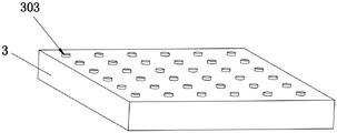
图4为本实用新型中盲道的结构示意图。FIG. 4 is a schematic structural diagram of a blind road in the present invention.
具体实施方式Detailed ways
下面参照附图说明本实用新型的具体实施方式。The specific embodiments of the present invention will be described below with reference to the accompanying drawings.
参考图1和图2,一种多功能石材加工机,包括机架1、钻孔装置2、切割装置5以及用于架空石材3的工作台8。机架1包括底座101以及固设于底座101的龙门架102。工作台8可前后移动地设置于底座101,钻孔装置2和切割装置5前后错开设置在龙门架102两侧且位于工作台8的上方。钻孔装置2和切割装置5通过第一电动二维滑台4和第二电动二维滑台6进行上下左右移动。Referring to FIG. 1 and FIG. 2 , a multifunctional stone processing machine includes a
参考图1和图2,工作台8通过电动丝杆滑动机构前后移动地设置于底座101。具体地,电动丝杆滑动机构包括第三电机92、滑轨91、第二滚轮组93以及其他组件,底座101固设有两条前后延伸的滑轨91,工作台8底部设有与两条滑轨91相配合的第二滚轮组93。由于电动丝杆滑动机构属于一种常见的直线型滑动机械结构,包括可转动设置于底座丝杆、固设于工作台8底部的螺母滑块等的上述其他组件在此不再赘述。Referring to FIG. 1 and FIG. 2 , the
参考图1和图2,龙门架102的一侧设有钻孔装置2、第一电动二维滑台4和左右方向延伸的第一轨道103。钻孔装置2包括第一机座22和四个沿左右方向间隔排列设置的钻头21,钻头21可转动地设置于第一机座22,并且相邻两钻头21通过第一电机23共同驱动。相邻两钻头21、一钻头21与第一电机23之间通过皮带传动。第一电机23的数量和钻头21的排列设置可以根据石材3加工的具体情况进行更改。第一电动二维滑台4包括第一滑台411、第三滑台421以及其他组件。第一机座22固设于第一滑台411,第一滑台411连接有第一升降电机412和第一升降丝杆413,第一滑台411可相对第三滑台421上下移动,机架1连接有第一平移电机422和穿设于第三滑台421的第一平移丝杆423,第三滑台421在第一轨道103上左右移动。Referring to FIGS. 1 and 2 , one side of the
参考图1和图2,龙门架102的另一侧设有切割装置5、第二电动二维滑台6和左右方向延伸的第二轨道104。第二电动二维滑台6包括第二滑台611、第四滑台621以及其他组件。切割装置5包括第二机座52和两个沿左右方向间隔排列的刀盘51,刀盘51可转动地设置于第二机座52,并且两刀盘51通过第二电机53共同驱动。刀盘51与第二电机53之间通过皮带传动。第二电机53的数量和刀盘51的排列设置可以根据石材3加工的具体情况进行更改。第二电动二维滑台6包括第二滑台611和第四滑台621。第二机座52固设于第二滑台611,第二滑台611连接有第二升降电机612和第二升降丝杆613,第二滑台611可相对第四滑台621上下移动,机架1连接有第二平移电机622和穿设于第四滑台621的第二平移丝杆623,第四滑台621在第二轨道104上左右移动。Referring to FIGS. 1 and 2 , the other side of the
由于电动二维滑台移动机构属于常规技术,本领域技术人员可以参考现有技术进行实施,在此不再赘述。Since the electric two-dimensional sliding table moving mechanism belongs to the conventional technology, those skilled in the art can implement it with reference to the prior art, which will not be repeated here.
参考图1和图2,工作台8上端面设有用于架空石材3的支撑架。支撑架包括首尾依次连接的左支撑条71、前挡板73、右支撑条72和后挡板74,并且左支撑条71和右支撑条72均设置有与石材3相抵触的第一滚轮组76。Referring to FIG. 1 and FIG. 2 , the upper end surface of the
参考图1和图2,左支撑条71左侧和右支撑条72右侧设有安装槽75,前挡板73的两端和后挡板74的两端可调节地连接于安装槽75内,通过螺栓将前挡板73的两端和后挡板74的两端连接固定。根据加工的石材3大小,调节前挡板73和后挡板74于工作台8前后的位置。使用时,只需拆卸一块挡板就可以将石材3取出并且第一滚轮组76的设计让此过程更不费力。Referring to FIGS. 1 and 2 ,
参考图3,以加工一个条形槽为例,说明本实用新型的开槽方法:为钻孔装置2装配深孔钻头;将石材3放置于工作台8的支撑架上;由电动丝杆滑动机构将工作台8及石材3向前移动;先由钻孔装置2的深孔钻头在石板上加工出两个沿前后方向间隔设置的通孔301(钻孔装置2对石材3进行加工时,需使石材3停止不动);然后由切割装置5的两个刀盘51在两条虚线302上进行切割,从而在石材3上加工出一个条形槽。Referring to FIG. 3 , the slotting method of the present invention is described by taking the processing of a strip groove as an example: assembling a deep-hole drill for the drilling device 2; placing the
当然,为了架空石材,也可以在工作台上直接设置用于架空石材的镂空部,例如,工作台由采用若干条方钢搭建成的框体,框体的中间则形成用于架空石材的镂空部。Of course, in order to hollow out the stone, a hollow part for the hollow stone can also be directly set on the workbench. For example, the workbench is made of a frame made of several square steels, and the middle of the frame forms a hollow for the hollow stone. department.
参考图4,此外,为钻孔装置2装配上盲点钻头时,本实用新型还可以在石材3上加工出若干呈矩阵排列的圆形凸台303,从而将石材3加工成一块盲点石板。Referring to FIG. 4 , in addition, when assembling a blind spot drill bit for the drilling device 2 , the utility model can also process a plurality of
上述仅为本实用新型的具体实施方式,但本实用新型的设计构思并不局限于此,凡利用此构思对本实用新型进行非实质性的改动,均应属于侵犯本实用新型保护范围的行为。The above are only specific embodiments of the present utility model, but the design concept of the present utility model is not limited to this, and any non-substantial changes to the present utility model by using this concept should be regarded as acts that infringe the protection scope of the present utility model.
Claims (10)
Priority Applications (1)
| Application Number | Priority Date | Filing Date | Title |
|---|---|---|---|
| CN202020035627.1U CN211616146U (en) | 2020-01-08 | 2020-01-08 | A multifunctional stone processing machine |
Applications Claiming Priority (1)
| Application Number | Priority Date | Filing Date | Title |
|---|---|---|---|
| CN202020035627.1U CN211616146U (en) | 2020-01-08 | 2020-01-08 | A multifunctional stone processing machine |
Publications (1)
| Publication Number | Publication Date |
|---|---|
| CN211616146U true CN211616146U (en) | 2020-10-02 |
Family
ID=72636353
Family Applications (1)
| Application Number | Title | Priority Date | Filing Date |
|---|---|---|---|
| CN202020035627.1U Expired - Fee Related CN211616146U (en) | 2020-01-08 | 2020-01-08 | A multifunctional stone processing machine |
Country Status (1)
| Country | Link |
|---|---|
| CN (1) | CN211616146U (en) |
Cited By (4)
| Publication number | Priority date | Publication date | Assignee | Title |
|---|---|---|---|---|
| CN112757495A (en) * | 2021-01-15 | 2021-05-07 | 中建科技集团有限公司 | Prestressed hollow slab cutting and punching machine |
| CN115070858A (en) * | 2022-06-17 | 2022-09-20 | 中冶建工集团有限公司 | Automatic tapping equipment for rubber layer of sports ground |
| CN115070857A (en) * | 2022-06-17 | 2022-09-20 | 中冶建工集团有限公司 | Rubber tapping equipment for sports ground |
| CN116001038A (en) * | 2023-01-31 | 2023-04-25 | 天长市天荣木业制品厂 | Drilling, slotting and edging all-in-one machine |
-
2020
- 2020-01-08 CN CN202020035627.1U patent/CN211616146U/en not_active Expired - Fee Related
Cited By (6)
| Publication number | Priority date | Publication date | Assignee | Title |
|---|---|---|---|---|
| CN112757495A (en) * | 2021-01-15 | 2021-05-07 | 中建科技集团有限公司 | Prestressed hollow slab cutting and punching machine |
| CN115070858A (en) * | 2022-06-17 | 2022-09-20 | 中冶建工集团有限公司 | Automatic tapping equipment for rubber layer of sports ground |
| CN115070857A (en) * | 2022-06-17 | 2022-09-20 | 中冶建工集团有限公司 | Rubber tapping equipment for sports ground |
| CN115070858B (en) * | 2022-06-17 | 2024-08-06 | 中冶建工集团有限公司 | Automatic perforating equipment for rubber layer of sports ground |
| CN115070857B (en) * | 2022-06-17 | 2024-08-06 | 中冶建工集团有限公司 | Sports field rubber hole opening equipment |
| CN116001038A (en) * | 2023-01-31 | 2023-04-25 | 天长市天荣木业制品厂 | Drilling, slotting and edging all-in-one machine |
Similar Documents
| Publication | Publication Date | Title |
|---|---|---|
| CN113478235B (en) | Efficient door and window profile machining production line and machining method thereof | |
| CN103962602B (en) | numerical control multi-shaft gantry drilling and milling machine tool | |
| CN104626291B (en) | Band is engraved the vertical of milling and is sent plate numerical control drilling | |
| CN107738321B (en) | Double-headed wood tenon CNC machining mechanism and its machining method | |
| CN105642952A (en) | Die drilling tool | |
| CN206153610U (en) | Multiaxis gang drill bed with adjustable | |
| CN115138889A (en) | Drilling machine suitable for 360-degree circumferential machining of cylindrical section | |
| CN105215416A (en) | A kind of chain sheet processing machine | |
| CN207807977U (en) | A kind of timber process equipment | |
| CN113799273A (en) | Four-knife cutting machine and cutting method thereof | |
| CN204622240U (en) | Band is engraved the vertical of milling and is sent plate numerical control drilling | |
| CN107225256A (en) | The vertical turning structure of turnning and milling boring multipurpose horizontal lathe | |
| CN205364109U (en) | Double head mobile gantry type machining center | |
| CN206326698U (en) | A kind of timber horizontal Machining centers | |
| CN206718060U (en) | New both-end numerical control tenon milling machine | |
| CN215545955U (en) | Novel laser cutting machine's change table | |
| CN207494714U (en) | A kind of high performance steel cutter device that can be moved | |
| CN2925729Y (en) | Automatic drill for drilling central hole on spindle | |
| CN205020914U (en) | Large -scale integral key shaft processingequipment | |
| CN213997973U (en) | A planer tool holder assembly | |
| CN111545796B (en) | A portable three-dimensional drilling machine | |
| CN211306618U (en) | Multifunctional machining mechanism of numerical control woodworking machine tool | |
| CN201471002U (en) | A vertical metal band sawing machine | |
| CN211566491U (en) | Numerical control machining equipment for edges of lightweight concrete wallboard | |
| CN209738645U (en) | Three-dimensional carving machine |
Legal Events
| Date | Code | Title | Description |
|---|---|---|---|
| GR01 | Patent grant | ||
| GR01 | Patent grant | ||
| CF01 | Termination of patent right due to non-payment of annual fee | ||
| CF01 | Termination of patent right due to non-payment of annual fee |
Granted publication date: 20201002 |