CN211614429U - A drilling device with high safety performance - Google Patents
A drilling device with high safety performance Download PDFInfo
- Publication number
- CN211614429U CN211614429U CN202020194505.7U CN202020194505U CN211614429U CN 211614429 U CN211614429 U CN 211614429U CN 202020194505 U CN202020194505 U CN 202020194505U CN 211614429 U CN211614429 U CN 211614429U
- Authority
- CN
- China
- Prior art keywords
- protection device
- high safety
- protection
- groove
- plate
- Prior art date
- Legal status (The legal status is an assumption and is not a legal conclusion. Google has not performed a legal analysis and makes no representation as to the accuracy of the status listed.)
- Active
Links
Images


Landscapes
- Drilling And Boring (AREA)
- Processing Of Stones Or Stones Resemblance Materials (AREA)
Abstract
本实用新型提供一种具有高安全性能的钻孔装置,包括保护装置,保护装置内设有工作台,内壁顶部设有移动槽,移动槽底部的两侧设有保护板,保护板的一侧设有一号电动推杆,工作台和保护装置的底部之间设有减震弹簧,工作台上设有滑槽,滑槽内设有移动板,移动板的一侧设有二号电动推杆,保护装置的顶部设有支架,一侧设有吸尘机,支架的底部设有连接块,连接块的底部设有伸缩气缸,伸缩气缸底部设有机壳,机壳内设有驱动电机,驱动电机的底部设有转轴,所述转轴的底部设有钻头。本实用新型设计简单,生产成本低,且设有保护装置,可避免钻孔过程中存在的危险,保护工作人员的健康安全。
The utility model provides a drilling device with high safety performance, which comprises a protection device, a workbench is arranged in the protection device, a moving groove is arranged on the top of the inner wall, protection plates are arranged on both sides of the bottom of the moving groove, and one side of the protection plate is arranged There is a No. 1 electric push rod, a shock-absorbing spring is arranged between the worktable and the bottom of the protection device, a chute is provided on the worktable, a moving plate is arranged in the chute, and a No. 2 electric push rod is arranged on one side of the moving plate , the top of the protection device is provided with a bracket, one side is provided with a vacuum cleaner, the bottom of the bracket is provided with a connecting block, the bottom of the connecting block is provided with a telescopic cylinder, the bottom of the telescopic cylinder is provided with a casing, and a driving motor is arranged in the casing, The bottom of the driving motor is provided with a rotating shaft, and the bottom of the rotating shaft is provided with a drill bit. The utility model has the advantages of simple design and low production cost, and is provided with a protection device, which can avoid the danger existing in the drilling process and protect the health and safety of the staff.
Description
技术领域technical field
本实用新型涉及金属加工技术领域,具体涉及一种具有高安全性能的钻孔装置。The utility model relates to the technical field of metal processing, in particular to a drilling device with high safety performance.
背景技术Background technique
钻孔装置广泛应用于金属加工成型的生产中,在工业生产中起着十分重要的作用,在对金属进行钻孔时,会产生大量的碎屑,对生产中操作人员的健康带来了很大的影响,目前市场上广泛使用的钻孔设备大多没有专门的保护装置,钻头使用中可能会发生断裂,断裂的钻头飞出,如果没有相关保护措施,钻头会对装置和操作人员的安全和健康带来极大的伤害,而且现在使用的钻孔设备大多结构复杂,生产成本高,对企业的生产带来的很大的负担,为此,我们提供一种具有高安全性能的钻孔装置。Drilling devices are widely used in the production of metal processing and forming, and play a very important role in industrial production. When drilling metal, a large amount of debris will be generated, which brings great harm to the health of operators in production. Most of the drilling equipment widely used in the market currently has no special protection device. The drill bit may break during use, and the broken drill bit will fly out. If there is no relevant protection measures, the drill bit will affect the safety of the device and operators. Health brings great harm, and most of the drilling equipment currently used has complex structure, high production cost, and brings a great burden to the production of enterprises. For this reason, we provide a drilling device with high safety performance. .
实用新型内容Utility model content
为了解决上述问题,我们设计了一种结构简单、造价成本低、对碎屑进行有效收集的一种具有高安全性能的钻孔装置。In order to solve the above problems, we designed a drilling device with simple structure, low cost and effective collection of debris with high safety performance.
本实用新型所采用的技术方案是:一种具有高安全性能的钻孔装置,包括保护装置,所述保护装置内设有工作台,内壁顶部设有移动槽,所述移动槽底部的两侧设有保护板,所述保护板的一侧设有一号电动推杆,所述工作台和保护装置的底部之间设有减震弹簧,所述工作台上设有滑槽,所述滑槽内设有移动板,所述移动板的一侧设有二号电动推杆,所述保护装置的顶部设有支架,一侧设有吸尘机,所述支架的底部设有连接块,所述连接块的底部设有伸缩气缸,所述伸缩气缸底部设有机壳,所述机壳内设有驱动电机,所述驱动电机的底部设有转轴,所述转轴的底部设有钻头。The technical scheme adopted by the utility model is: a drilling device with high safety performance, comprising a protection device, a worktable is arranged in the protection device, a moving groove is arranged at the top of the inner wall, and two sides of the bottom of the moving groove are arranged There is a protection plate, one side of the protection plate is provided with a No. 1 electric push rod, a shock-absorbing spring is arranged between the worktable and the bottom of the protection device, and a chute is provided on the worktable, and the chute There is a moving plate inside, one side of the moving plate is provided with a No. 2 electric push rod, the top of the protection device is provided with a bracket, one side is provided with a vacuum cleaner, and the bottom of the bracket is provided with a connecting block, so The bottom of the connecting block is provided with a telescopic cylinder, the bottom of the telescopic cylinder is provided with a casing, the casing is provided with a driving motor, the bottom of the driving motor is provided with a rotating shaft, and the bottom of the rotating shaft is provided with a drill bit.
进一步的,所述吸尘机一侧设有吸尘导管,另一侧设有排屑管,所述吸尘导管穿过保护装置侧壁进入保护装置内,对钻孔中产生的碎屑进行吸取收集。Further, one side of the vacuum cleaner is provided with a dust suction duct, and the other side is provided with a chip discharge pipe. suction collection.
进一步的,所述移动板内设有凹槽,所述凹槽内设有螺纹杆,所述螺纹杆上套设有压板,通过对螺纹杆的转动使压板上下移动,对金属进行固定。Further, a groove is provided in the moving plate, a threaded rod is arranged in the groove, and a pressing plate is sleeved on the threaded rod, and the pressing plate is moved up and down by rotating the threaded rod to fix the metal.
进一步的,所述保护装置的正面设有观察窗,所述观察窗呈透明设置且可以打开,对金属进行放置,便于对金属的放置和对钻孔过程的观察。Further, an observation window is provided on the front of the protection device, and the observation window is transparent and can be opened to place the metal, so as to facilitate the placement of the metal and the observation of the drilling process.
进一步的,所述机壳一侧设有散风口,所述散风口的一侧设有滤网,对驱动电机进行具有散热和防尘的作用。Further, one side of the casing is provided with an air diffuser, and one side of the air diffuser is provided with a filter screen to dissipate heat and prevent dust to the drive motor.
进一步的,所述转轴和钻头活动连接,便于更换。Further, the rotating shaft and the drill bit are movably connected for easy replacement.
本实用新型的有益效果是:1、设置了保护装置,当钻头向下移动进入保护装置内,打开一号伸缩推杆,保护板向中间移动,对移动槽进行封闭,且保护板不与机壳接触,如果钻头使用时发生断裂,保护装置将钻头进行保护,防止钻头飞出,并通过观察窗发现,及时关闭电源,保护工作人员的安全;2、设置了吸尘机,将钻孔过程中产生的废屑进行收集,避免乱飞,危害工作人员的身体健康,同时废屑被收集,便于通过观察窗观察钻孔的情况;3、设置了减震弹簧,对工作台起到减震缓冲的作用,避免钻孔过程中压力过大造成工作台损坏。The beneficial effects of the utility model are as follows: 1. A protection device is provided, when the drill bit moves down into the protection device, the No. 1 telescopic push rod is opened, the protection plate moves to the middle, and the moving groove is closed, and the protection plate is not connected with the machine. If the drill bit breaks during use, the protection device will protect the drill bit to prevent the drill bit from flying out, and it will be found through the observation window, and the power will be turned off in time to protect the safety of the staff; The waste chips generated in the drilling process are collected to avoid flying around and endanger the health of the staff. At the same time, the waste chips are collected to facilitate the observation of the drilling conditions through the observation window; 3. A shock-absorbing spring is installed to dampen the workbench. The function of buffering can avoid the damage of the workbench caused by excessive pressure during the drilling process.
附图说明Description of drawings
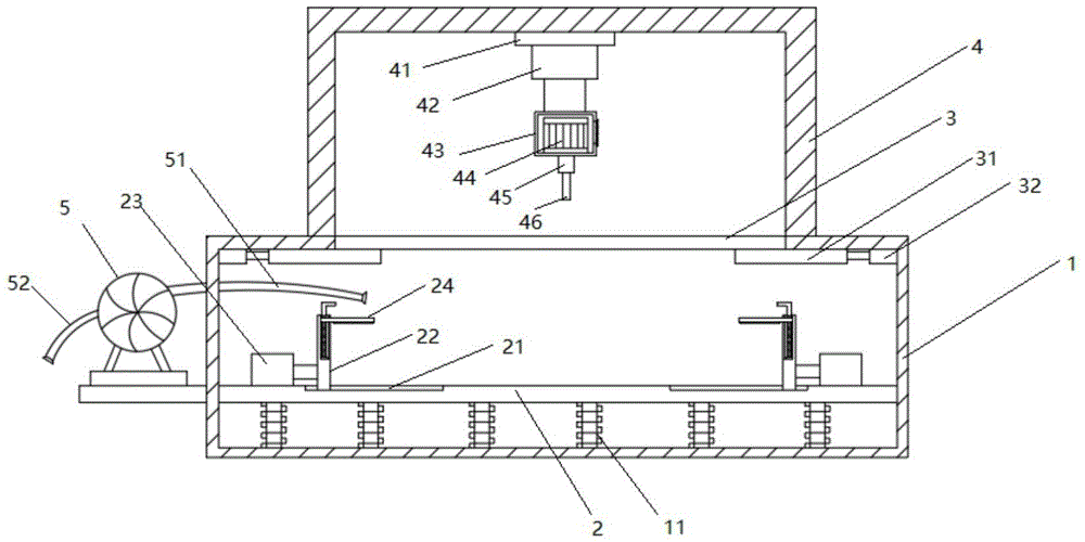
图1是本实用新型结构示意图。FIG. 1 is a schematic structural diagram of the present utility model.
图2是本实用新型外部结构示意图。Figure 2 is a schematic diagram of the external structure of the present invention.
图3是本实用新型移动板的结构示意图。FIG. 3 is a schematic view of the structure of the mobile board of the present invention.
图4是本实用新型驱动电机的结构示意图。FIG. 4 is a schematic structural diagram of the drive motor of the present invention.
1保护装置、11减震弹簧、2工作台、21一号电动推杆、22移动板、221凹槽、222螺纹杆、23二号电动推杆、24压板、3移动槽、31保护板、32一号电动推杆、4支架、41连接块、42伸缩气缸、43机壳、431散风口、432滤网、44驱动电机、45转轴、46钻头、5吸尘机、51吸尘导管、52排屑导管、6观察窗。1 protection device, 11 shock spring, 2 worktable, 21 No. 1 electric push rod, 22 moving plate, 221 groove, 222 threaded rod, 23 No. 2 electric push rod, 24 pressure plate, 3 moving groove, 31 protection plate, 32 No. 1 electric push rod, 4 brackets, 41 connection blocks, 42 telescopic cylinders, 43 casings, 431 air vents, 432 filters, 44 drive motors, 45 shafts, 46 drill bits, 5 vacuum cleaners, 51 vacuum ducts, 52 chip ducts, 6 observation windows.
具体实施方式Detailed ways
下面将结合本实用新型实施例中的附图,对本实用新型实施例中的技术方案进行清楚、完整地描述,显然,所描述的实施例仅仅是本实用新型一部分实施例,而不是全部的实施例。The technical solutions in the embodiments of the present utility model will be clearly and completely described below with reference to the accompanying drawings in the embodiments of the present utility model. Obviously, the described embodiments are only a part of the embodiments of the present utility model, rather than all the implementations. example.
如图1-4所示,一种具有高安全性能的钻孔装置,包括保护装置1,所述保护装置1内设有工作台2,内壁顶部设有移动槽3,所述移动槽3底部的两侧设有保护板31,所述保护板31的一侧设有一号电动推杆32,所述工作台2和保护装置1的底部之间设有减震弹簧11,所述工作台2上设有滑槽21,所述滑槽21内设有移动板22,所述移动板22的一侧设有二号电动推杆23,所述保护装置1的顶部设有支架4,一侧设有吸尘机5,所述支架4的底部设有连接块41,所述连接块41的底部设有伸缩气缸42,所述伸缩气缸42底部设有机壳43,所述机壳43内设有驱动电机44,所述驱动电机44的底部设有转轴45,所述转轴45的底部设有钻头46。As shown in Figures 1-4, a drilling device with high safety performance includes a
在本实用新型结构中,所述吸尘机5一侧设有吸尘导管51,另一侧设有排屑导管52,所述吸尘导管51穿过保护装置1侧壁进入保护装置1内,对产生的碎屑进行吸取收集;所述移动板22内设有凹槽221,所述凹槽221内设有螺纹杆222,所述螺纹杆222上套设有压板24,通过对螺纹杆222的转动使压板24上下移动,对金属进行固定;所述保护装置1的正面设有观察窗6,所述观察窗6呈透明设置且可以打开,对金属进行放置,便于对金属的放置和对钻孔过程的观察;所述机壳43一侧设有散风口431,所述散风口431的一侧设有滤网432,对驱动电机44进行散热和防尘的作用;所述转轴45和钻头46活动连接,便于更换。In the structure of the present invention, the
本实用新型的工作原理是:打开观察窗6,将金属块放在工作台2上,打开二号电动推杆23,带动移动板22移动,对金属块进行夹紧,再顺时针转动螺纹杆222,使压板24向下移动,对金属块上表面进行压紧,打开伸缩气缸42,伸缩气缸42带动驱动电机44和钻头46向下移动,当钻头46接触到金属块时,打开一号电动推杆32,间接带动保护板31向中间运动,对移动槽3进行封闭,但保护板31不与机壳43接触,再打开驱动电机44和吸尘机5,钻头46对金属块打孔,吸尘导管51对废屑进行收集。The working principle of the utility model is as follows: open the
以上所述,仅为本实用新型较佳的具体实施方式,但本实用新型的保护范围并不局限于此,任何熟悉本技术领域的技术人员在本实用新型揭露的技术范围内,根据本实用新型的技术方案及其实用新型构思加以等同替换或改变,都应涵盖在本实用新型的保护范围之内。The above are only the preferred specific embodiments of the present invention, but the protection scope of the present invention is not limited to this. Equivalent replacement or modification of the new technical solution and its utility model concept shall be included within the protection scope of the present utility model.
Claims (6)
Priority Applications (1)
| Application Number | Priority Date | Filing Date | Title |
|---|---|---|---|
| CN202020194505.7U CN211614429U (en) | 2020-02-22 | 2020-02-22 | A drilling device with high safety performance |
Applications Claiming Priority (1)
| Application Number | Priority Date | Filing Date | Title |
|---|---|---|---|
| CN202020194505.7U CN211614429U (en) | 2020-02-22 | 2020-02-22 | A drilling device with high safety performance |
Publications (1)
| Publication Number | Publication Date |
|---|---|
| CN211614429U true CN211614429U (en) | 2020-10-02 |
Family
ID=72618920
Family Applications (1)
| Application Number | Title | Priority Date | Filing Date |
|---|---|---|---|
| CN202020194505.7U Active CN211614429U (en) | 2020-02-22 | 2020-02-22 | A drilling device with high safety performance |
Country Status (1)
| Country | Link |
|---|---|
| CN (1) | CN211614429U (en) |
Cited By (2)
| Publication number | Priority date | Publication date | Assignee | Title |
|---|---|---|---|---|
| CN112792514A (en) * | 2021-01-25 | 2021-05-14 | 广东雅励新材料股份有限公司 | Process method and device for improving machining precision of aluminum plate |
| CN113145885A (en) * | 2021-04-30 | 2021-07-23 | 南京量瑞颂机械有限公司 | Intelligent drilling equipment for section bar machining for improving drilling precision |
-
2020
- 2020-02-22 CN CN202020194505.7U patent/CN211614429U/en active Active
Cited By (4)
| Publication number | Priority date | Publication date | Assignee | Title |
|---|---|---|---|---|
| CN112792514A (en) * | 2021-01-25 | 2021-05-14 | 广东雅励新材料股份有限公司 | Process method and device for improving machining precision of aluminum plate |
| CN112792514B (en) * | 2021-01-25 | 2021-10-01 | 广东雅励新材料股份有限公司 | Process method and device for improving machining precision of aluminum plate |
| CN113145885A (en) * | 2021-04-30 | 2021-07-23 | 南京量瑞颂机械有限公司 | Intelligent drilling equipment for section bar machining for improving drilling precision |
| CN113145885B (en) * | 2021-04-30 | 2024-12-20 | 佛山市诚欧金属建材有限公司 | An intelligent drilling device for profile processing with improved drilling accuracy |
Similar Documents
| Publication | Publication Date | Title |
|---|---|---|
| CN113751425B (en) | Dust removal device for electric automation equipment | |
| CN210934244U (en) | Desktop hole drilling machine dust collection device | |
| CN216228572U (en) | A CNC grinding device that automatically collects waste chips | |
| CN220944341U (en) | Drilling grinding equipment for self-lubricating bearing machining | |
| CN216654682U (en) | A kind of crushing device for mining machinery | |
| CN215038128U (en) | Drilling equipment is used in integrated circuit board production | |
| CN213498427U (en) | Polishing machine with dust suction device | |
| CN211940471U (en) | A safety protection device for cylinder liner grinding | |
| CN212020933U (en) | A punching device for carbon fiber automobile hood processing | |
| CN218556502U (en) | A kind of end grinding machine for semi-shaft casing | |
| CN209077854U (en) | A kind of processing unit (plant) of people's air defense fitting for door axle center hole | |
| CN218669275U (en) | Dust falling device for drilling machine | |
| CN216298713U (en) | A lathe scrap collector | |
| CN210721302U (en) | Dust protected mainframe box for computer | |
| CN210360530U (en) | Milling machine with dust removal function | |
| CN209986283U (en) | Drilling equipment | |
| CN221081635U (en) | Drilling device for circuit board processing | |
| CN217860265U (en) | Triaxial steel pipe intersecting line cutting machine | |
| CN220029563U (en) | Numerical control machine tool with safety protection device | |
| CN221389035U (en) | Isolation protection device | |
| CN219445614U (en) | Perforating device for fire-fighting installation | |
| CN222720892U (en) | Automatic dust collector of automatically controlled cabinet | |
| CN220812320U (en) | Grease heat absorbing device for edible oil production | |
| CN219171150U (en) | Dust absorption formula medium density fiberboard processing equipment | |
| CN222077464U (en) | Dust collecting equipment is used in chip packaging processing |
Legal Events
| Date | Code | Title | Description |
|---|---|---|---|
| GR01 | Patent grant | ||
| GR01 | Patent grant | ||
| TR01 | Transfer of patent right |
Effective date of registration: 20250910 Address after: 335000 Jiangxi city of Yingtan Province Lake area Longgang near Hong Lu Deng Patentee after: YINGTAN ZHONGXINCHENG COPPER Co.,Ltd. Country or region after: China Address before: 335000 in the factory building of Yingtan zhongxincheng Copper Co., Ltd., next to denghong Road, Yingtan hi tech Industrial Development Zone, Jiangxi Province Patentee before: Jiangxi Yuanguangshun Science and Technology Co-innovation Co.,Ltd. Country or region before: China |
|
| TR01 | Transfer of patent right |