CN211603737U - A multifunctional radiology viewing device - Google Patents
A multifunctional radiology viewing device Download PDFInfo
- Publication number
- CN211603737U CN211603737U CN201922240751.1U CN201922240751U CN211603737U CN 211603737 U CN211603737 U CN 211603737U CN 201922240751 U CN201922240751 U CN 201922240751U CN 211603737 U CN211603737 U CN 211603737U
- Authority
- CN
- China
- Prior art keywords
- fixed
- fixedly arranged
- multifunctional
- spring
- viewing device
- Prior art date
- Legal status (The legal status is an assumption and is not a legal conclusion. Google has not performed a legal analysis and makes no representation as to the accuracy of the status listed.)
- Expired - Fee Related
Links
Images


Landscapes
- Apparatus For Radiation Diagnosis (AREA)
Abstract
本实用新型公开了一种多功能放射科用观片装置,本实用新型涉及医疗设备技术领域,包括固定座,所述固定座顶部设有固定机构;所述固定机构包括背面板,所述背面板一侧固定设有灯光板,所述面板和灯光板顶部均固定设有顶板,所述顶板底部固定设有连接块,所述连接块一侧固定设有定位筒,所述定位筒内部固定设有第一弹簧,所述第一弹簧一端固定设有滑杆,所述滑杆与定位筒滑动连接。本实用新型通过设置固定机构,通过横截面形状设置为三角的导向块有效的将影像图片进行倾斜导向,从而将影像图片与灯光板进行分离,提高了医学影像片的固定稳定性,同时提升了医学影像片的取出便捷性。
The utility model discloses a multifunctional radiology film viewing device, which relates to the technical field of medical equipment. The utility model comprises a fixing seat, the top of the fixing seat is provided with a fixing mechanism; A lighting board is fixed on one side of the panel, a top board is fixed on the top of the panel and the lighting board, a connecting block is fixed on the bottom of the top board, a positioning cylinder is fixed on one side of the connecting block, and the positioning cylinder is fixed inside. A first spring is provided, one end of the first spring is fixed with a sliding rod, and the sliding rod is slidably connected with the positioning cylinder. By arranging a fixing mechanism, the utility model effectively tilts and guides the image picture through the guide block whose cross-sectional shape is set as a triangle, so as to separate the image picture and the lighting board, improve the fixing stability of the medical image film, and at the same time improve the The convenience of taking out medical images.
Description
技术领域technical field
本实用新型涉及医疗设备技术领域,具体为一种多功能放射科用观片装置。The utility model relates to the technical field of medical equipment, in particular to a multifunctional radiology viewing device.
背景技术Background technique
放射科一直以来都是综合医院的传统必备科室,为医院的医疗保健科研教学工作做出了很大的贡献,随着电子计算机技术、现代物理学、电子学与传统放射学的有机结合,使现代放射医学插上了高科技的翅膀,放射科在医疗领域显示出了新的活力,在诊治工作中的地位越来越不可代替。Radiology has always been a traditional necessary department in general hospitals, and has made great contributions to the hospital's medical and health care scientific research and teaching work. With the organic combination of computer technology, modern physics, electronics and traditional radiology, The modern radiology has been equipped with high-tech wings, and the radiology department has shown new vitality in the medical field, and its status in the diagnosis and treatment work is becoming more and more irreplaceable.
现有技术做法所产生的技术问题:现有的放射科用观片设备在对医学影像片进行固定时常常固定不稳定,在紧贴到灯光板上后取出较为繁琐。The technical problems caused by the prior art method: the existing radiology viewing equipment is often unstable when fixing the medical image, and it is cumbersome to take out after it is closely attached to the light board.
实用新型内容Utility model content
针对现有技术的不足,本实用新型提供了一种多功能放射科用观片装置,解决了现有的放射科用观片设备在对医学影像片进行固定时常常固定不稳定,在紧贴到灯光板上后取出较为繁琐的问题。Aiming at the deficiencies of the prior art, the utility model provides a multifunctional radiology viewing device, which solves the problem that the existing radiology viewing equipment is often unstable when fixing medical image sheets, and it is After reaching the light board, take out the more tedious problems.
为实现以上目的,本实用新型通过以下技术方案予以实现:一种多功能放射科用观片装置,包括固定座,所述固定座顶部设有固定机构;In order to achieve the above purpose, the present invention is achieved through the following technical solutions: a multifunctional radiology film viewing device, comprising a fixing seat, and a fixing mechanism is provided on the top of the fixing seat;
所述固定机构包括背面板,所述背面板一侧固定设有灯光板,所述面板和灯光板顶部均固定设有顶板,所述顶板底部固定设有连接块,所述连接块一侧固定设有定位筒,所述定位筒内部固定设有第一弹簧,所述第一弹簧一端固定设有滑杆,所述滑杆与定位筒滑动连接,所述滑杆一端设有压板,所述压板底部固定设有导向板,所述导向板为倾斜设置,所述滑杆一端与压板表面铰接,所述压板一侧固定设有压条,所述固定座一侧固定设有导向块,所述导向块横截面形状设置为三角形。The fixing mechanism includes a back panel, one side of the back panel is fixed with a lighting panel, both the panel and the top of the lighting panel are fixedly provided with a top panel, the bottom of the top panel is fixedly provided with a connecting block, and one side of the connecting block is fixed A positioning cylinder is provided, a first spring is fixed inside the positioning cylinder, a sliding rod is fixed at one end of the first spring, the sliding rod is slidably connected with the positioning cylinder, and a pressure plate is provided at one end of the sliding rod. A guide plate is fixedly arranged at the bottom of the pressure plate, the guide plate is arranged obliquely, one end of the sliding rod is hinged with the surface of the pressure plate, a pressure strip is fixed on one side of the pressure plate, and a guide block is fixed on one side of the fixed seat. The guide block cross-sectional shape is set to a triangle.
优选的,所述固定座底部设有调节机构,所述调节机构包括调节筒,所述调节机构内部设有调节杆,所述调节杆表面固定设有滚珠,所述调节杆与调节筒滑动连接。Preferably, the bottom of the fixed seat is provided with an adjustment mechanism, the adjustment mechanism includes an adjustment cylinder, an adjustment rod is arranged inside the adjustment mechanism, a ball is fixed on the surface of the adjustment rod, and the adjustment rod is slidably connected to the adjustment cylinder .
优选的,所述调节杆外侧固定设有卡环,所述卡环顶部固定设有第二弹簧。Preferably, a snap ring is fixed on the outside of the adjusting rod, and a second spring is fixed on the top of the snap ring.
优选的,所述第二弹簧一端固定设有撑板,所述撑板一端固定设有固定壳,所述撑板中部与卡环铰接。Preferably, a support plate is fixed at one end of the second spring, a fixing shell is fixed at one end of the support plate, and the middle part of the support plate is hinged with the snap ring.
优选的,所述调节杆底部固定设有底座,所述底座底部固定设有万向轮。Preferably, a base is fixed at the bottom of the adjusting rod, and a universal wheel is fixed at the bottom of the base.
优选的,所述背面板和灯光板均与固定座固定连接。Preferably, both the back panel and the light panel are fixedly connected to the fixing base.
优选的,所述压条由橡胶材料制成。Preferably, the bead is made of rubber material.
有益效果beneficial effect
本实用新型提供了一种多功能放射科用观片装置。具备以下有益效果:The utility model provides a multifunctional radiology film viewing device. Has the following beneficial effects:
1、通过设置固定机构,使用时将影像图片紧贴到灯光板上,之后推动影像图片,影像图片卡入到压板与灯光板之间的缝隙处,同时第一弹簧带动滑杆在定位筒内部滑动,之后滑杆推动压将影像图片进行挤压固定,设置的由橡胶材料制成的压条有效的提升对影像图片的摩擦系数,同时提高了对影像图片的保护效果,之后按动影像图片在表面下滑,通过横截面形状设置为三角的导向块有效的将影像图片进行倾斜导向,从而将影像图片与灯光板进行分离,提高了医学影像片的固定稳定性,同时提升了医学影像片的取出便捷性。1. By setting the fixing mechanism, when in use, the image picture is closely attached to the light plate, and then the image picture is pushed, and the image picture is stuck in the gap between the pressure plate and the light plate, and the first spring drives the sliding rod inside the positioning cylinder. Slide, and then push the slide bar to squeeze and fix the image. The set pressure bar made of rubber material can effectively improve the friction coefficient of the image and improve the protection effect of the image. The surface slides down, and the image picture is effectively tilted and guided by the guide block with the cross-sectional shape set as a triangle, so as to separate the image picture from the light board, improve the fixing stability of the medical image film, and improve the removal of the medical image film. Convenience.
2、通过设置调节机构,撑板带动固定壳与调节杆分离,撑板翻转时带动第二弹簧延展,之后推动背面板带动调节筒进行多角度旋转,设置在调节杆表面固定设有的滚珠提升调节筒的调节效率,固定时松开撑板,第二弹簧带动撑板驱动固定壳卡在调节筒上,从而有效的对调节筒进行固定。2. By setting the adjustment mechanism, the support plate drives the fixed shell to separate from the adjustment rod. When the support plate is turned over, it drives the second spring to extend, and then pushes the back plate to drive the adjustment cylinder to rotate at multiple angles. The balls fixed on the surface of the adjustment rod are lifted. To adjust the adjustment efficiency of the cylinder, loosen the support plate when fixing, and the second spring drives the support plate to drive the fixed shell to be stuck on the adjustment cylinder, thereby effectively fixing the adjustment cylinder.
附图说明Description of drawings
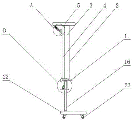
图1为本实用新型整体结构示意图;Fig. 1 is the overall structure schematic diagram of the present utility model;
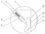
图2为本实用新型图1中A部局部结构示意图;Fig. 2 is the partial structure schematic diagram of A part in Fig. 1 of the utility model;
图3为本实用新型图1中B部局部结构示意图;Fig. 3 is the partial structure schematic diagram of part B in Fig. 1 of the utility model;
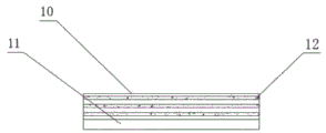
图4为本实用新型压板结构示意图。FIG. 4 is a schematic diagram of the structure of the pressing plate of the present invention.
图中:1-固定座、2-固定机构、3-背面板、4-灯光板、5-顶板、6-连接块、7-定位筒、8-第一弹簧、9-滑杆、10-压板、11-导向板、12-压条、13-导向块、14-调节机构、15-调节筒、16-调节杆、17-滚珠、18-卡环、19-第二弹簧、20-撑板、21-固定壳、22-底座、23-万向轮。In the figure: 1-fixed seat, 2-fixed mechanism, 3-back panel, 4-lighting board, 5-top panel, 6-connecting block, 7-positioning cylinder, 8-first spring, 9-slider, 10- Pressure plate, 11-guide plate, 12-pressure strip, 13-guide block, 14-adjustment mechanism, 15-adjustment cylinder, 16-adjustment rod, 17-ball, 18-retention ring, 19-second spring, 20-support plate , 21-Fixed shell, 22-Base, 23-Universal wheel.
具体实施方式Detailed ways
下面将结合本实用新型实施例中的附图,对本实用新型实施例中的技术方案进行清楚、完整地描述,显然,所描述的实施例仅仅是本实用新型一部分实施例,而不是全部的实施例。基于本实用新型中的实施例,本领域普通技术人员在没有做出创造性劳动前提下所获得的所有其他实施例,都属于本实用新型保护的范围。The technical solutions in the embodiments of the present utility model will be clearly and completely described below with reference to the accompanying drawings in the embodiments of the present utility model. Obviously, the described embodiments are only a part of the embodiments of the present utility model, rather than all the implementations. example. Based on the embodiments of the present invention, all other embodiments obtained by those of ordinary skill in the art without creative work fall within the protection scope of the present invention.
请参阅图1-4,本实用新型提供一种技术方案:一种多功能放射科用观片装置,包括固定座1,所述固定座1顶部设有固定机构2;Please refer to FIGS. 1-4 , the present invention provides a technical solution: a multifunctional radiology viewing device, comprising a
所述固定机构2包括背面板3,所述背面板3一侧固定设有灯光板4,所述面板和灯光板4顶部均固定设有顶板5,所述顶板5底部固定设有连接块6,所述连接块6一侧固定设有定位筒7,所述定位筒7内部固定设有第一弹簧8,所述第一弹簧8一端固定设有滑杆9,所述滑杆9与定位筒7滑动连接,所述滑杆9一端设有压板10,所述压板10底部固定设有导向板11,所述导向板11为倾斜设置,所述滑杆9一端与压板10表面铰接,所述压板10一侧固定设有压条12,所述固定座1一侧固定设有导向块13,所述导向块13横截面形状设置为三角形;The
所述背面板3和灯光板4均与固定座1固定连接;The
所述压条12由橡胶材料制成。The
实施方式具体为:使用时将影像图片紧贴到灯光板4上,之后推动影像图片,影像图片卡入到压板10与灯光板4之间的缝隙处,同时第一弹簧8带动滑杆9在定位筒7内部滑动,之后滑杆9推动压将影像图片进行挤压固定,设置的由橡胶材料制成的压条12有效的提升对影像图片的摩擦系数,同时提高了对影像图片的保护效果,之后按动影像图片在表面下滑,通过横截面形状设置为三角的导向块13有效的将影像图片进行倾斜导向,从而将影像图片与灯光板4进行分离,提高了医学影像片的固定稳定性,同时提升了医学影像片的取出便捷性,该实施方式具体解决了现有技术中存在的现有的放射科用观片设备在对医学影像片进行固定时常常固定不稳定,在紧贴到灯光板4上后取出较为繁琐对的问题。The specific embodiment is as follows: when in use, the image picture is closely attached to the
如附图3所示的一种多功能放射科用观片装置,还包括调节机构14,所述调节机构14设置在固定座1底部,所述调节机构14包括调节筒15,所述调节机构14内部设有调节杆16,所述调节杆16表面固定设有滚珠17,所述调节杆16与调节筒15滑动连接;As shown in FIG. 3, a multifunctional radiology film viewing device further includes an
所述调节杆16外侧固定设有卡环18,所述卡环18顶部固定设有第二弹簧19;A
所述第二弹簧19一端固定设有撑板20,所述撑板20一端固定设有固定壳21,所述撑板20中部与卡环18铰接;One end of the
所述调节杆16底部固定设有底座22,所述底座22底部固定设有万向轮23。A
实施方式具体为:按动撑板20,撑板20带动固定壳21与调节杆16分离,撑板20翻转时带动第二弹簧19延展,之后推动背面板3带动调节筒15进行多角度旋转,设置在调节杆16表面固定设有的滚珠17提升调节筒15的调节效率,固定时松开撑板20,第二弹簧19带动撑板20驱动固定壳21卡在调节筒15上,从而有效的对调节筒15进行固定,该实施方式具体解决了现有技术中存在的不能方便对灯光板4进行多角度调节的问题。The specific embodiment is: pressing the
本实用新型工作原理:The working principle of the utility model:
参照说明书附图1-4,使用时将影像图片紧贴到灯光板4上,之后推动影像图片,影像图片卡入到压板10与灯光板4之间的缝隙处,同时第一弹簧8带动滑杆9在定位筒7内部滑动,之后滑杆9推动压将影像图片进行挤压固定,设置的由橡胶材料制成的压条12有效的提升对影像图片的摩擦系数,同时提高了对影像图片的保护效果,之后按动影像图片在表面下滑,通过横截面形状设置为三角的导向块13有效的将影像图片进行倾斜导向,从而将影像图片与灯光板4进行分离,提高了医学影像片的固定稳定性,同时提升了医学影像片的取出便捷性;Referring to the accompanying drawings 1-4 in the specification, when using, the image picture is tightly attached to the
参照说明书附图3,撑板20带动固定壳21与调节杆16分离,撑板20翻转时带动第二弹簧19延展,之后推动背面板3带动调节筒15进行多角度旋转,设置在调节杆16表面固定设有的滚珠17提升调节筒15的调节效率,固定时松开撑板20,第二弹簧19带动撑板20驱动固定壳21卡在调节筒15上,从而有效的对调节筒15进行固定。Referring to FIG. 3 of the specification, the
需要说明的是,在本文中,诸如第一和第二等之类的关系术语仅仅用来将一个实体或者操作与另一个实体或操作区分开来,而不一定要求或者暗示这些实体或操作之间存在任何这种实际的关系或者顺序。而且,术语“包括”、“包含”或者其任何其他变体意在涵盖非排他性的包含,从而使得包括一系列要素的过程、方法、物品或者设备不仅包括那些要素,而且还包括没有明确列出的其他要素,或者是还包括为这种过程、方法、物品或者设备所固有的要素。It should be noted that, in this document, relational terms such as first and second are used only to distinguish one entity or operation from another entity or operation, and do not necessarily require or imply any relationship between these entities or operations. any such actual relationship or sequence exists. Moreover, the terms "comprising", "comprising" or any other variation thereof are intended to encompass a non-exclusive inclusion such that a process, method, article or device that includes a list of elements includes not only those elements, but also includes not explicitly listed or other elements inherent to such a process, method, article or apparatus.
尽管已经示出和描述了本实用新型的实施例,对于本领域的普通技术人员而言,可以理解在不脱离本实用新型的原理和精神的情况下可以对这些实施例进行多种变化、修改、替换和变型,本实用新型的范围由所附权利要求及其等同物限定。Although the embodiments of the present invention have been shown and described, it will be understood by those skilled in the art that various changes and modifications can be made to these embodiments without departing from the principles and spirit of the present invention , alternatives and modifications, the scope of the present invention is defined by the appended claims and their equivalents.
Claims (7)
Priority Applications (1)
| Application Number | Priority Date | Filing Date | Title |
|---|---|---|---|
| CN201922240751.1U CN211603737U (en) | 2019-12-14 | 2019-12-14 | A multifunctional radiology viewing device |
Applications Claiming Priority (1)
| Application Number | Priority Date | Filing Date | Title |
|---|---|---|---|
| CN201922240751.1U CN211603737U (en) | 2019-12-14 | 2019-12-14 | A multifunctional radiology viewing device |
Publications (1)
| Publication Number | Publication Date |
|---|---|
| CN211603737U true CN211603737U (en) | 2020-09-29 |
Family
ID=72592366
Family Applications (1)
| Application Number | Title | Priority Date | Filing Date |
|---|---|---|---|
| CN201922240751.1U Expired - Fee Related CN211603737U (en) | 2019-12-14 | 2019-12-14 | A multifunctional radiology viewing device |
Country Status (1)
| Country | Link |
|---|---|
| CN (1) | CN211603737U (en) |
-
2019
- 2019-12-14 CN CN201922240751.1U patent/CN211603737U/en not_active Expired - Fee Related
Similar Documents
| Publication | Publication Date | Title |
|---|---|---|
| CN112068316A (en) | Radiology department image diagnosis and film reading device and using method thereof | |
| CN204945499U (en) | Sheet devices is seen in a kind of gripping easily special image of dept. of radiology | |
| CN210771123U (en) | Spectrum projector | |
| CN207114896U (en) | A kind of portable iconography film viewing apparatus | |
| CN110814126B (en) | A kind of hollow glass aluminum frame folding mechanism | |
| CN206175980U (en) | Multi -media support is used in information technology teaching convenient to carry | |
| CN221351874U (en) | Medical image film fixing device | |
| CN210029471U (en) | Medical image printing device | |
| CN216485817U (en) | Mobile film reading device | |
| CN209202308U (en) | A kind of height-adjustable music easel | |
| CN206378646U (en) | Simple diagnostic imaging diagosis fixed mount | |
| CN210872761U (en) | A mandibular bracket for preventing tongue from falling back | |
| CN211375195U (en) | An auxiliary device for radiology image diagnosis and reading | |
| CN208256277U (en) | A kind of multi-functional music stand for vocal music training | |
| CN210051966U (en) | Radiographic image film reading device | |
| CN220256677U (en) | Postoperative labor-saving turning-over auxiliary device | |
| CN218585102U (en) | Novel film viewer for medical image | |
| CN211460568U (en) | Support frame is adjusted with head to throat's operation | |
| CN209729152U (en) | A kind of contrast learning device for marketing teaching | |
| CN210687651U (en) | Computer display and all-in-one machine for teaching | |
| CN221467707U (en) | Communication equipment with real-time positioning function | |
| CN219380421U (en) | A strip clamping device | |
| CN211730788U (en) | A research note board for general practitioners | |
| CN219459131U (en) | A portable mobile phone stand | |
| CN219645963U (en) | Tongue depressor for veterinary examination |
Legal Events
| Date | Code | Title | Description |
|---|---|---|---|
| GR01 | Patent grant | ||
| GR01 | Patent grant | ||
| CF01 | Termination of patent right due to non-payment of annual fee |
Granted publication date: 20200929 Termination date: 20211214 |
|
| CF01 | Termination of patent right due to non-payment of annual fee |