CN211590796U - Slotting device for distribution line installation - Google Patents
Slotting device for distribution line installation Download PDFInfo
- Publication number
- CN211590796U CN211590796U CN201922013971.0U CN201922013971U CN211590796U CN 211590796 U CN211590796 U CN 211590796U CN 201922013971 U CN201922013971 U CN 201922013971U CN 211590796 U CN211590796 U CN 211590796U
- Authority
- CN
- China
- Prior art keywords
- machine body
- blade
- air outlet
- organism
- slotting device
- Prior art date
- Legal status (The legal status is an assumption and is not a legal conclusion. Google has not performed a legal analysis and makes no representation as to the accuracy of the status listed.)
- Expired - Fee Related
Links
- 238000009826 distribution Methods 0.000 title claims abstract description 16
- 238000009434 installation Methods 0.000 title claims abstract description 14
- 238000003825 pressing Methods 0.000 claims abstract description 8
- 238000005096 rolling process Methods 0.000 claims description 17
- 238000005192 partition Methods 0.000 claims description 9
- 239000000428 dust Substances 0.000 abstract description 12
- 238000000034 method Methods 0.000 abstract description 7
- 238000010276 construction Methods 0.000 description 3
- 238000009792 diffusion process Methods 0.000 description 3
- XLYOFNOQVPJJNP-UHFFFAOYSA-N water Substances O XLYOFNOQVPJJNP-UHFFFAOYSA-N 0.000 description 3
- 238000005520 cutting process Methods 0.000 description 2
- 230000033001 locomotion Effects 0.000 description 2
- 230000004075 alteration Effects 0.000 description 1
- 230000009286 beneficial effect Effects 0.000 description 1
- 230000005540 biological transmission Effects 0.000 description 1
- 239000011449 brick Substances 0.000 description 1
- 238000012986 modification Methods 0.000 description 1
- 230000004048 modification Effects 0.000 description 1
- 239000004575 stone Substances 0.000 description 1
- 238000006467 substitution reaction Methods 0.000 description 1
Images

Landscapes
- Processing Of Stones Or Stones Resemblance Materials (AREA)
Abstract
The utility model discloses a distribution lines installation is with fluting device, including organism, spring and antifriction bearing, the left and right sides of organism is provided with the support, and the support one side of keeping away from the organism central line is provided with the walking cylinder, the inside of walking cylinder is provided with the pivot, the top of organism sets up and carries the pressure handrail, and carries the right side of pressing the handrail and be provided with the push-and-pull handrail, the inside of organism is provided with the blade, and the inboard of blade is provided with fixed blade holder, the inside of fixed blade holder is provided with the main shaft, both sides are provided with the spacing ring around the fixed blade holder, and one side that the organism central line was kept away from to the spacing. This slotting device is used in distribution lines installation compares with current ordinary slotting device, and depth of cut accessible cylinder control has reduced the dust that the fluting in-process produced, and it is healthy to protect constructor, and contracts the tool bit internal after the grooving, prevents that constructor from touching high-speed rotatory blade by mistake and be injured.
Description
Technical Field
The utility model relates to a fluting technical field specifically is a fluting device is used in distribution lines installation.
Background
With the continuous progress and development of society, more and more buildings appear around our life, and these buildings can not avoid burying all kinds of electric wires in wall or ground in the construction, reduce the use wearing and tearing of electric wire on the one hand, on the other hand also improves the security, and in the electric wire wiring, need carry out the fluting processing through the fluting device with the wall to the electric wire can be laid line smoothly.
The grooving machine for wiring of the existing building is inconvenient in control of the grooving depth, cannot meet actual requirements of different wiring pipe diameters, is low in construction efficiency, generates a large amount of dust in the grooving process, harms the health of constructors, cannot well meet the use requirements of people, and carries out technical innovation on the basis of the existing grooving device aiming at the above situation.
SUMMERY OF THE UTILITY MODEL
An object of the utility model is to provide a distribution lines installation is with fluting device to provide the inconvenient control of general groover fluting machine depth of cut in solving above-mentioned background art, can not satisfy the actual demand of different wiring pipe diameters, the efficiency of construction is low, and produces a large amount of dusts among the fluting process, endangers constructor healthy, can not be fine satisfies people's user demand problem.
In order to achieve the above object, the utility model provides a following technical scheme: a slotting device for distribution line installation comprises a machine body, a spring and a rolling bearing, wherein supports are arranged on the left side and the right side of the machine body, a walking roller is arranged on one side, away from the center line of the machine body, of each support, a rotating shaft is arranged inside the walking roller, a lifting and pressing handrail is arranged above the machine body, a push-pull handrail is arranged on the right side of the lifting and pressing handrail, a blade is arranged inside the machine body, a fixed blade holder is arranged on the inner side of the blade, a main shaft is arranged inside the fixed blade holder, limiting rings are arranged on the front side and the rear side of the fixed blade holder, a partition plate is arranged on one side, away from the center line of the machine body, of each limiting ring, a guide groove is arranged at the lower end of each partition plate, an L-shaped connecting plate is arranged on, one side that organism central line was kept away from to the cylinder is provided with the dead lever, and the inboard of dead lever is provided with the spring, the inboard of spring is provided with the telescopic link, and the below of telescopic link is provided with antifriction bearing, antifriction bearing's right side is provided with the motor, the rear of organism is provided with the gear box, and the inside of gear box is provided with the gear, the inboard of gear is provided with the parallel key, the right side of blade is provided with the filter screen, and the right side of filter screen is provided with the fan, the right side of fan is provided with the air outlet, and the outside of air outlet is provided with out the tuber pipe, the outside of going out.
Preferably, the telescopic rod is fixedly connected with the rolling bearing, and the inner surface of the rolling bearing is attached to the inner surface of the main shaft.
Preferably, the blades and the main shaft form an integrated structure through the fixed blade holder, and the blades are arranged at equal intervals along the horizontal plane.
Preferably, the air outlet is connected with the machine body through a bolt, and the outer surface of the air outlet is attached to the inner surface of the air outlet pipe.
Preferably, the fixed rods are fixedly connected with the machine body, and the fixed rods are symmetrical with each other about the center line of the machine body.
Preferably, the L-shaped connecting plate is respectively connected with the air cylinders and the partition plate through bolts, and the air cylinders are symmetrical with each other about the center line of the machine body.
Compared with the prior art, the beneficial effects of the utility model are as follows:
1. the utility model controls the slotting depth of the slotting machine by arranging the blade, the main shaft, the cylinder, the fixed cutter holder and the piston rod, the cylinder pushes the main shaft to move downwards by the piston rod, so that the blade moves downwards to start to cut the wall surface or the ground, and the length of the blade extending out of the machine body is adjusted by controlling the air inlet and the air outlet of the cylinder;
2. the utility model reduces the dust generated in the grooving process through the arrangement of the filter screen, the fan, the air outlet and the air outlet pipe, blocks the stone generated in the grooving process through the filter screen, sucks out the dust generated in the grooving process through the fan, and leads the dust into the bucket filled with water through the air outlet and the air outlet pipe, thereby reducing the diffusion of the dust;
3. the utility model discloses a dead lever, spring, telescopic link and antifriction bearing's setting for the grooving machine is after work, and the blade kick-backs, prevents that high-speed rotatory blade from hindering the people, and after grooving machine work, the cylinder stops the downstream, and the top that arrives is stopped in the top motion of beginning, and the spring shrink that is drawn drives antifriction bearing and main shaft upward movement, and in the blade retraction organism.
Drawings
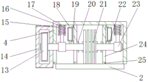
FIG. 1 is a schematic view of a front view half-section structure of the present invention;
FIG. 2 is a left side view of the utility model;
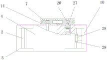
fig. 3 is a schematic view of the overlooking half-section structure of the present invention.
In the figure: 1. a rotating shaft; 2. a traveling roller; 3. a support; 4. a body; 5. lifting and pressing the handrail; 6. a blade; 7. a main shaft; 8. a filter screen; 9. a fan; 10. pushing and pulling the handrail; 11. an air outlet; 12. an air outlet pipe; 13. a gear; 14. a gear case; 15. fixing the rod; 16. a spring; 17. a telescopic rod; 18. a cylinder; 19. an L-shaped connecting plate; 20. a limiting ring; 21. fixing the tool apron; 22. a piston rod; 23. a rolling bearing; 24. a guide groove; 25. a partition plate; 26. a flat bond; 27. an electric motor; 28. buckling; 29. and (4) bolts.
Detailed Description
The technical solutions in the embodiments of the present invention will be described clearly and completely with reference to the accompanying drawings in the embodiments of the present invention, and it is obvious that the described embodiments are only some embodiments of the present invention, not all embodiments. Based on the embodiments in the present invention, all other embodiments obtained by a person skilled in the art without creative work belong to the protection scope of the present invention.
Referring to fig. 1-3, the present invention provides a technical solution: a slotting device for distribution line installation comprises a machine body 4, a spring 16 and a rolling bearing 23, wherein supports 3 are arranged on the left side and the right side of the machine body 4, a walking roller 2 is arranged on one side, away from the central line of the machine body 4, of each support 3, a rotating shaft 1 is arranged inside each walking roller 2, a lifting and pressing handrail 5 is arranged above the machine body 4, a push-pull handrail 10 is arranged on the right side of each lifting and pressing handrail 5, a blade 6 is arranged inside the machine body 4, a fixed blade seat 21 is arranged on the inner side of each blade 6, each blade 6 and a main shaft 7 form an integrated structure through the fixed blade seat 21, the blades 6 are arranged at equal intervals along a horizontal plane, a main shaft 7 is arranged inside each fixed blade seat 21, limiting rings 20 are arranged on the front side and the rear side of each fixed blade seat 21, a partition plate 25 is arranged on one side, away from the central line of the machine body, the cylinder 18 is arranged on one side, away from the center line of the machine body 4, of the L-shaped connecting plate 19, the L-shaped connecting plate 19 is connected with the cylinder 18 and the partition plate 25 through bolts 29, the cylinders 18 are symmetrical about the center line of the machine body 4, the grooving depth of the grooving machine is controlled through arrangement of the blade 6, the main shaft 7, the cylinder 18, the fixed tool apron 21 and the piston rod 22, the cylinder 18 pushes the main shaft 7 to move downwards through the piston rod 22, the blade 6 moves downwards to start cutting the wall surface or the ground, and the length of the blade 6 extending out of the machine body 4 is adjusted through control of air inlet and exhaust of the cylinder 18;
a piston rod 22 is arranged on the lower side of the cylinder 18, a fixing rod 15 is arranged on one side, away from the center line of the machine body 4, of the cylinder 18, a spring 16 is arranged on the inner side of the fixing rod 15, the fixing rod 15 is fixedly connected with the machine body 4, the fixing rods 15 are symmetrical with respect to the center line of the machine body 4, and through the arrangement of the fixing rod 15, the spring 16, the telescopic rod 17 and the rolling bearing 23, after the operation of the slot cutting machine is finished, the blade 6 rebounds to prevent the blade 6 rotating at a high speed from hurting people;
an expansion link 17 is arranged on the inner side of the spring 16, a rolling bearing 23 is arranged below the expansion link 17, the expansion link 17 is fixedly connected with the rolling bearing 23, the inner surface of the rolling bearing 23 is attached to the inner surface of the spindle 7, a motor 27 is arranged on the right side of the rolling bearing 23, a gear box 14 is arranged behind the machine body 4, a gear 13 is arranged inside the gear box 14, a flat key 26 is arranged on the inner side of the gear 13, a filter screen 8 is arranged on the right side of the blade 6, a fan 9 is arranged on the right side of the filter screen 8, an air outlet 11 is arranged on the right side of the fan 9, an air outlet pipe 12 is arranged on the outer side of the air outlet 11, the air outlet 11 is connected with the machine body 4 through a bolt 29, the outer surface of the air outlet 11 is attached to the inner surface of the air, the dust is introduced into the barrel filled with water through the air outlet 11 and the air outlet pipe 12, the diffusion of the dust is reduced, the buckle 28 is arranged on the outer side of the air outlet pipe 12, the bolt 29 is arranged above the buckle 28, and the dust generated in the grooving process is reduced through the arrangement of the filter screen 8, the fan 9, the air outlet 11 and the air outlet pipe 12.
The working principle is as follows: when the slotting device for installing the distribution line is used, firstly, a starting button is pressed, a motor 27 is started, a key groove and a flat key 26 on an output shaft of the motor 27 drive a gear 13 to rotate, a main shaft 7 is driven to rotate through the transmission of a gear 13 in a gear box 14, a blade 6 is driven to rotate through a fixed tool apron 21 fixedly connected with the main shaft 7, a cylinder 18 is started, the cylinder 18 pushes the main shaft 7 to move downwards through a piston rod 22, the blade 6 moves downwards, the wall surface or the ground is cut, dust generated by slotting is sucked out by a fan 9, broken bricks generated by slotting are blocked by a filter screen 8, the dust is introduced into a barrel filled with water through an air outlet 11 and an air outlet pipe 12, the diffusion of the dust is reduced, after the slotting is finished, the starting button is pressed, the motor 27 is closed, the cylinder 18 is contracted, and a telescopic rod 17 and a rolling bearing 23 fixedly connected with the telescopic rod 17 are driven, because the main shaft 7 is matched with inner holes of the left rolling bearing 23 and the right rolling bearing 23, the blade 6 is lifted into the machine body 4, the rotating blade 6 is prevented from hurting people, and the operation principle of the slotting device for installing the distribution line is the same.
Although embodiments of the present invention have been shown and described, it will be appreciated by those skilled in the art that changes, modifications, substitutions and alterations can be made in these embodiments without departing from the principles and spirit of the invention, the scope of which is defined in the appended claims and their equivalents.
Claims (6)
1. The utility model provides a distribution lines installation is with fluting device, includes organism (4), spring (16) and antifriction bearing (23), its characterized in that: the machine body is characterized in that supports (3) are arranged on the left side and the right side of the machine body (4), a walking roller (2) is arranged on one side, away from the center line of the machine body (4), of each support (3), a rotating shaft (1) is arranged inside each walking roller (2), a lifting and pressing handrail (5) is arranged above the machine body (4), a push-pull handrail (10) is arranged on the right side of each lifting and pressing handrail (5), a blade (6) is arranged inside the machine body (4), a fixed blade holder (21) is arranged on the inner side of each blade (6), a main shaft (7) is arranged inside each fixed blade holder (21), limiting rings (20) are arranged on the front side and the rear side of each fixed blade holder (21), a partition plate (25) is arranged on one side, away from the center line of the machine body (4), a guide groove (24) is arranged at the lower end of each partition plate (25), and an L-shaped, and one side of the L-shaped connecting plate (19) far away from the center line of the machine body (4) is provided with an air cylinder (18), the lower side of the air cylinder (18) is provided with a piston rod (22), one side of the air cylinder (18) far away from the center line of the machine body (4) is provided with a fixed rod (15), the inner side of the fixed rod (15) is provided with a spring (16), the inner side of the spring (16) is provided with a telescopic rod (17), a rolling bearing (23) is arranged below the telescopic rod (17), the right side of the rolling bearing (23) is provided with an electric motor (27), the rear part of the machine body (4) is provided with a gear box (14), a gear (13) is arranged inside the gear box (14), the inner side of the gear (13) is provided with a flat key (26), the right side of the blade, the right side of fan (9) is provided with air outlet (11), and the outside of air outlet (11) is provided with out tuber pipe (12), the outside of going out tuber pipe (12) is provided with buckle (28), and the top of buckle (28) is provided with bolt (29).
2. The slotting device for distribution line installation according to claim 1, wherein: the telescopic rod (17) is fixedly connected with the rolling bearing (23), and the inner surface of the rolling bearing (23) is attached to the inner surface of the main shaft (7).
3. The slotting device for distribution line installation according to claim 1, wherein: the blades (6) and the main shaft (7) form an integrated structure through the fixed cutter holder (21), and the blades (6) are arranged at equal intervals along the horizontal plane.
4. The slotting device for distribution line installation according to claim 1, wherein: the air outlet (11) is connected with the machine body (4) through a bolt (29), and the outer surface of the air outlet (11) is attached to the inner surface of the air outlet pipe (12).
5. The slotting device for distribution line installation according to claim 1, wherein: the fixing rods (15) are fixedly connected with the machine body (4), and the fixing rods (15) are symmetrical about the center line of the machine body (4).
6. The slotting device for distribution line installation according to claim 1, wherein: the L-shaped connecting plate (19) is respectively connected with the air cylinders (18) and the partition plate (25) through bolts (29), and the air cylinders (18) are symmetrical with each other about the central line of the machine body (4).
Priority Applications (1)
| Application Number | Priority Date | Filing Date | Title |
|---|---|---|---|
| CN201922013971.0U CN211590796U (en) | 2019-11-20 | 2019-11-20 | Slotting device for distribution line installation |
Applications Claiming Priority (1)
| Application Number | Priority Date | Filing Date | Title |
|---|---|---|---|
| CN201922013971.0U CN211590796U (en) | 2019-11-20 | 2019-11-20 | Slotting device for distribution line installation |
Publications (1)
| Publication Number | Publication Date |
|---|---|
| CN211590796U true CN211590796U (en) | 2020-09-29 |
Family
ID=72588472
Family Applications (1)
| Application Number | Title | Priority Date | Filing Date |
|---|---|---|---|
| CN201922013971.0U Expired - Fee Related CN211590796U (en) | 2019-11-20 | 2019-11-20 | Slotting device for distribution line installation |
Country Status (1)
| Country | Link |
|---|---|
| CN (1) | CN211590796U (en) |
Cited By (1)
| Publication number | Priority date | Publication date | Assignee | Title |
|---|---|---|---|---|
| CN112246373A (en) * | 2020-10-30 | 2021-01-22 | 安徽科达机电有限公司 | Concrete body bottom skin crushing device and bottom skin removing system |
-
2019
- 2019-11-20 CN CN201922013971.0U patent/CN211590796U/en not_active Expired - Fee Related
Cited By (1)
| Publication number | Priority date | Publication date | Assignee | Title |
|---|---|---|---|---|
| CN112246373A (en) * | 2020-10-30 | 2021-01-22 | 安徽科达机电有限公司 | Concrete body bottom skin crushing device and bottom skin removing system |
Similar Documents
| Publication | Publication Date | Title |
|---|---|---|
| CN111282702A (en) | Broken dust collector of abandonment brick and tile | |
| CN109290619A (en) | A kind of tubing efficient cutting | |
| CN103742153B (en) | A kind of sandstone miner | |
| CN208343195U (en) | A kind of ceramic tile seaming and cutting cutting mill | |
| CN210731934U (en) | Concrete buffing machine for construction | |
| CN205394852U (en) | A excavating gear for pipeline ditch | |
| CN210705370U (en) | Electric piping fluting device is used in building electromechanical installation | |
| CN219485277U (en) | Polishing device for vertical machining center | |
| CN220362345U (en) | Surface polishing equipment for fiber cement pressure plate | |
| CN208913259U (en) | It is a kind of can multidirectional cutting machining set-up | |
| CN111564793A (en) | Indoor electric wire burying device | |
| CN217702867U (en) | Slotting equipment for building water and electricity installation | |
| CN206703317U (en) | A kind of ceramic tile cutter for preventing airborne dust | |
| CN216157086U (en) | A horizontal concrete removing mechanism | |
| CN223877245U (en) | A building plumbing trenching device | |
| CN109483360A (en) | A kind of surface spikes high efficiency rotary removal device | |
| CN109382715A (en) | A kind of surface spikes high efficiency rotary removal device | |
| CN209035553U (en) | A kind of tubing efficient cutting | |
| CN205348702U (en) | Automatic change milling cutter type fluting ware | |
| CN211923416U (en) | Multifunctional dust-absorption type slotting machine | |
| CN203412263U (en) | Dual dust removal type computer full automatic grooving machine | |
| CN214187360U (en) | Edge trimmer is used in bathtub production and processing | |
| CN108327091A (en) | A kind of power wiring wall grooving apparatus | |
| CN211571343U (en) | Joint cutting equipment for highway engineering construction | |
| CN112192760A (en) | Quick power-on wire slot device |
Legal Events
| Date | Code | Title | Description |
|---|---|---|---|
| GR01 | Patent grant | ||
| GR01 | Patent grant | ||
| CF01 | Termination of patent right due to non-payment of annual fee | ||
| CF01 | Termination of patent right due to non-payment of annual fee |
Granted publication date: 20200929 |