CN211590511U - High-density shaving board convenient to install - Google Patents
High-density shaving board convenient to install Download PDFInfo
- Publication number
- CN211590511U CN211590511U CN201921988438.XU CN201921988438U CN211590511U CN 211590511 U CN211590511 U CN 211590511U CN 201921988438 U CN201921988438 U CN 201921988438U CN 211590511 U CN211590511 U CN 211590511U
- Authority
- CN
- China
- Prior art keywords
- fixedly connected
- plate body
- groove
- board
- board body
- Prior art date
- Legal status (The legal status is an assumption and is not a legal conclusion. Google has not performed a legal analysis and makes no representation as to the accuracy of the status listed.)
- Expired - Fee Related
Links
Images


Landscapes
- Workshop Equipment, Work Benches, Supports, Or Storage Means (AREA)
Abstract
The utility model relates to a shaving board technical field just discloses a high density shaving board convenient to installation, including first plate body and second plate body, first plate body right side fixedly connected with plectane, the spout has all been seted up at both ends about the plectane, two the inside slip of spout is provided with the limiting plate, two limiting plate left side fixedly connected with telescopic link, telescopic link other end fixed connection is in spout left side lateral wall, the spring has been cup jointed in the activity of the spout outside, spring right side and limiting plate fixed connection, spring left side and spout left side lateral wall fixed connection, circular cavity has been seted up in the inside left side of second plate body, the round hole has been seted up in circular cavity left side, the spacing groove has been seted up to both ends symmetry about the round hole, circular cavity both sides are provided with. The utility model discloses it is more convenient, labour saving and time saving to make the installation of high density shaving board.
Description
Technical Field
The utility model relates to a shaving board technical field especially relates to a high density shaving board convenient to installation.
Background
Particle board is also called bagasse board, and is an artificial board made of crushed materials made of wood or other lignocellulose materials and glued under the action of heat and pressure after adhesive is applied, and is also called crushed material board. It is mainly used for furniture manufacture, building industry and train and automobile carriage manufacture.
The shaving board structure is more even, and the processability is good, can process into the panel by a wide margin as required, but high density shaving board is difficult for fixing when the installation is used, wastes time and energy, and difficult dismantlement.
SUMMERY OF THE UTILITY MODEL
The utility model aims at solving the problem that the shaving board is difficult for fixing when installing and using, wastes time and energy, and is difficult for dismantling, and the high density shaving board convenient to installation that provides.
In order to achieve the above purpose, the utility model adopts the following technical scheme:
the utility model provides a high density shaving board convenient to installation, includes first plate body and second plate body, first plate body right side fixedly connected with plectane, the spout has all been seted up at both ends about the plectane, two the inside slip of spout is provided with the limiting plate, two limiting plate left side fixedly connected with telescopic link, telescopic link other end fixed connection is in spout left side lateral wall, the spring has been cup jointed in the activity of the spout outside, spring right side and limiting plate fixed connection, spring left side and spout left side lateral wall fixed connection, circular cavity has been seted up in the inside left side of second plate body, the round hole has been seted up in circular cavity left side, inside the plectane passes through the round hole and inserts circular cavity, the spacing groove has been seted up to both ends symmetry about the round.
Preferably, the tight mechanism in top includes lead screw and round platform, circular cavity upside set up threaded hole, the lead screw pass through the screw hole with second plate body threaded connection, just the lead screw lower extreme extends to in the circular cavity and fixedly connected with round platform, the round platform respectively with two the limiting plate offsets the setting.
Preferably, the upper end and the lower end of the right side of the first plate body are both provided with an inserting plate groove, the upper end and the lower end of the left side of the second plate body are provided with inserting plates, and the inserting plates are inserted into the corresponding inserting plate grooves and are fixedly connected through bolts.
Preferably, the upper end and the bottom of the second plate body are provided with grooves, the grooves are internally provided with rotating wheels, and the screw rod penetrates through the second plate body, extends to the grooves and is fixedly connected with the rotating wheels.
Preferably, the limiting groove is arranged at 90 degrees with the round hole and the jack connected with the round hole.
Compared with the prior art, the utility model provides a high density shaving board convenient to installation possesses following beneficial effect:
1. this high density shaving board convenient to installation passes the round hole through the plectane, and the limiting plate passes the jack, rotatory certain angle, then rotatory runner drives the lead screw and selects the commentaries on classics to make the downward second plate body middle part of round platform move to push up the limiting plate tight left, make the limiting plate reach the spacing inslot, thereby connect first plate body and second plate body.
2. This high density shaving board convenient to installation inserts the picture peg groove that corresponds through the picture peg, through bolt-up connection for first plate body is connected more firm with the second plate body.
3. This high density shaving board convenient to installation through the reverse rotation lead screw, makes the round platform to the direction motion of keeping away from second plate body middle part to through the ejecting spacing groove of spring and telescopic link with the limiting plate, make first plate body and second plate body can separate after dismantling the bolt.
The part that does not relate to in the device all is the same with prior art or can adopt prior art to realize, the utility model discloses it is more convenient, labour saving and time saving to make the installation of high density shaving board.
Drawings
Fig. 1 is a schematic diagram of an assembled structure of a high-density particle board convenient to install according to the present invention;
fig. 2 is a schematic structural view of the left side of the second plate body of the high-density shaving board convenient to mount according to the present invention;
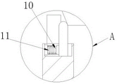
fig. 3 is an enlarged view of a portion a of fig. 1.
In the figure: the structure comprises a second plate body 1, a round hole 2, a limiting groove 3, a round cavity 4, a round table 5, a circular plate 6, a lead screw 7, a first plate body 8, a spring 10, an expansion rod 11, an inserting plate groove 12, a bolt 13, a groove 14, a limiting plate 15, a sliding groove 16, an inserting plate 17, a rotating wheel 18 and an inserting hole 19.
Detailed Description
The technical solutions in the embodiments of the present invention will be described clearly and completely with reference to the accompanying drawings in the embodiments of the present invention, and it is obvious that the described embodiments are only some embodiments of the present invention, not all embodiments.
In the description of the present invention, it is to be understood that the terms "upper", "lower", "front", "rear", "left", "right", "top", "bottom", "inner", "outer", and the like indicate orientations or positional relationships based on the orientations or positional relationships shown in the drawings, and are only for convenience of description and simplicity of description, and do not indicate or imply that the device or element being referred to must have a particular orientation, be constructed and operated in a particular orientation, and therefore, should not be construed as limiting the present invention.
Referring to fig. 1-3, a high-density shaving board convenient to mount comprises a first board body 8 and a second board body 1, wherein a circular board 6 is fixedly connected to the right side of the first board body 8, sliding grooves 16 are respectively formed at the upper end and the lower end of the circular board 6, limiting plates 15 are slidably arranged inside the two sliding grooves 16, telescopic rods 11 are fixedly connected to the left sides of the two limiting plates 15, the other ends of the telescopic rods 11 are fixedly connected to the left side walls of the sliding grooves 16, springs 10 are movably sleeved on the outer sides of the sliding grooves 16, the right sides of the springs 10 are fixedly connected with the limiting plates 15, the left sides of the sliding grooves 16 are fixedly connected with the left side walls of the sliding grooves 10, a circular cavity 4 is formed in the inside of the second board body 1, a circular hole 2 is formed in the left side of the circular cavity 4, the tight mechanism in top includes lead screw 7 and round platform 5, 4 upside screw holes have been seted up in circular cavity, lead screw 7 passes through screw hole and 1 threaded connection of second plate body, and 7 lower extremes of lead screw extend to in the circular cavity 4 and fixedly connected with round platform 5, round platform 5 offsets the setting with two limiting plates 15 respectively, picture peg groove 12 has all been seted up at both ends about the 8 right sides of first plate body, both ends are provided with picture peg 17 about the 1 left side of second plate body, picture peg 17 inserts and passes through bolt 13 fastening connection in the picture peg groove 12 that corresponds, recess 14 is seted up to 1 upper end of second plate body and bottom, the inside runner 18 that is provided with of recess 14, lead screw 7 runs through second plate body 1 and extends to recess 14 and with runner 18 fixed connection, spacing groove 3 with round hole 2 and the jack 19 of connecting are 90 degrees settings.
In the utility model, when in use, an installer inserts the circular plate 6 into the circular hole 2, and the limiting plate 15 passes through the jack 19, so that the circular plate 6 and the limiting plate 15 enter the circular cavity 4, then the first plate body 8 is rotated by 90 degrees, and then the rotating wheel 18 is rotated to drive the screw rod 7 to rotate selectively, so that the circular truncated cone 5 moves downwards to the middle part of the second plate body 1, thereby pushing the limit plate 15 to the left tightly, leading the limit plate 15 to reach the limit groove 3, leading the first plate body 8 and the second plate body 1 to be connected, inserting the inserting plate 17 into the corresponding inserting plate groove 12, the first plate body 8 and the second plate body 1 are firmly connected through the bolts 13, when the disassembly is needed, the circular truncated cone 5 moves towards the direction far away from the middle part of the second plate body 1 by reversely rotating the screw rod 7, thereby through spring 10 and telescopic link 11 with spacing plate 15 ejecting spacing groove 3 for first plate body 8 and second plate body 1 can separate after dismantling bolt 13.
The above, only be the concrete implementation of the preferred embodiment of the present invention, but the protection scope of the present invention is not limited thereto, and any person skilled in the art is in the technical scope of the present invention, according to the technical solution of the present invention and the utility model, the concept of which is equivalent to replace or change, should be covered within the protection scope of the present invention.
Claims (5)
1. The high-density shaving board convenient to install comprises a first board body (8) and a second board body (1), and is characterized in that a circular plate (6) is fixedly connected to the right side of the first board body (8), sliding grooves (16) are formed in the upper end and the lower end of the circular plate (6), two limiting plates (15) are arranged inside the sliding grooves (16) in a sliding mode, two limiting plates (15) are fixedly connected with a telescopic rod (11) on the left side of each limiting plate (15), the other end of the telescopic rod (11) is fixedly connected to the side wall on the left side of the corresponding sliding groove (16), a spring (10) is movably sleeved on the outer side of each sliding groove (16), the right side of the spring (10) is fixedly connected with the corresponding limiting plate (15), the left side of the spring (10) is fixedly connected with the side wall on the left side of the corresponding sliding groove (16), inside circular cavity (4) were inserted through round hole (2) plectane (6), round hole (2) both sides were connected with jack (19), spacing groove (3) have been seted up to round hole (2) upper and lower both ends symmetry, circular cavity (4) both sides are provided with the tight mechanism in top.
2. The high-density shaving board convenient to install according to claim 1, wherein the tightening mechanism comprises a screw rod (7) and a round table (5), a threaded hole is formed in the upper side of the circular cavity (4), the screw rod (7) is in threaded connection with the second board body (1) through a threaded hole, the lower end of the screw rod (7) extends into the circular cavity (4) and is fixedly connected with the round table (5), and the round table (5) is respectively abutted to the two limiting plates (15).
3. The high-density particle board convenient to install according to claim 1, wherein the upper and lower ends of the right side of the first board body (8) are provided with inserting board grooves (12), the upper and lower ends of the left side of the second board body (1) are provided with inserting boards (17), and the inserting boards (17) are inserted into the corresponding inserting board grooves (12) and are fixedly connected through bolts (13).
4. A high-density particle board convenient for installation according to claim 2, wherein the second board body (1) is provided with a groove (14) at the upper end and the bottom, a rotating wheel (18) is arranged in the groove (14), and the screw rod (7) extends through the second board body (1) to the groove (14) and is fixedly connected with the rotating wheel (18).
5. A high-density particle board convenient to mount according to claim 1, wherein the limiting groove (3) is arranged at 90 degrees with the round hole (2) and the plug hole (19) connected with the round hole.
Priority Applications (1)
| Application Number | Priority Date | Filing Date | Title |
|---|---|---|---|
| CN201921988438.XU CN211590511U (en) | 2019-11-18 | 2019-11-18 | High-density shaving board convenient to install |
Applications Claiming Priority (1)
| Application Number | Priority Date | Filing Date | Title |
|---|---|---|---|
| CN201921988438.XU CN211590511U (en) | 2019-11-18 | 2019-11-18 | High-density shaving board convenient to install |
Publications (1)
| Publication Number | Publication Date |
|---|---|
| CN211590511U true CN211590511U (en) | 2020-09-29 |
Family
ID=72588087
Family Applications (1)
| Application Number | Title | Priority Date | Filing Date |
|---|---|---|---|
| CN201921988438.XU Expired - Fee Related CN211590511U (en) | 2019-11-18 | 2019-11-18 | High-density shaving board convenient to install |
Country Status (1)
| Country | Link |
|---|---|
| CN (1) | CN211590511U (en) |
-
2019
- 2019-11-18 CN CN201921988438.XU patent/CN211590511U/en not_active Expired - Fee Related
Similar Documents
| Publication | Publication Date | Title |
|---|---|---|
| CN213682636U (en) | External heat-insulation inorganic active wall | |
| CN111945935B (en) | External wall panel connection system, wall panel node structure and installation method | |
| CN211194127U (en) | A PCB board mechanism of punching for 5G production usefulness | |
| CN112809856A (en) | High-density shaving board convenient to install | |
| CN206800733U (en) | A kind of energy-saving replaceable units curtain wall system | |
| CN220790287U (en) | Assembled light indoor ceiling structure | |
| CN218814432U (en) | Waterproof insulation construction of building outer wall | |
| CN115726503B (en) | Photovoltaic curtain wall with reinforcing mechanism | |
| CN201372572Y (en) | Compression-type magnetic sucker used for template | |
| CN215406514U (en) | Assembled energy-concerving and environment-protective type sunshine room | |
| CN216239529U (en) | Anion floor | |
| CN215106270U (en) | Energy-conserving thermal-insulated wall body that keeps warm of assembled building | |
| CN201110456Y (en) | Aluminium section and associated angle connector capable of mounting or dismounting | |
| CN203675493U (en) | Profile framework | |
| CN217759746U (en) | Decoration panel clamping device is exempted from to tear open inside and outside building wall | |
| CN216075917U (en) | Assembled wooden house plate | |
| CN208052228U (en) | A kind of fall arrest thermal insulation board nursing frame | |
| CN217299337U (en) | Anti-deformation rock wool board | |
| CN222325473U (en) | Automatic board turning device for furniture manufacturing | |
| CN215407183U (en) | Wood floor with stone texture imitation | |
| CN219671854U (en) | Heat preservation and insulation wallboard structure | |
| CN224097996U (en) | A wind-solar hybrid controller component | |
| CN221030649U (en) | Large-span building steel structure connection structure | |
| CN223978593U (en) | Assembled solar cell panel | |
| CN215871264U (en) | Installation base is used in installation of photovoltaic solar panel |
Legal Events
| Date | Code | Title | Description |
|---|---|---|---|
| GR01 | Patent grant | ||
| GR01 | Patent grant | ||
| CF01 | Termination of patent right due to non-payment of annual fee | ||
| CF01 | Termination of patent right due to non-payment of annual fee |
Granted publication date: 20200929 Termination date: 20211118 |