CN211574833U - Floor lamps for interior design with adjustable light source illumination angle - Google Patents
Floor lamps for interior design with adjustable light source illumination angle Download PDFInfo
- Publication number
- CN211574833U CN211574833U CN201922220359.0U CN201922220359U CN211574833U CN 211574833 U CN211574833 U CN 211574833U CN 201922220359 U CN201922220359 U CN 201922220359U CN 211574833 U CN211574833 U CN 211574833U
- Authority
- CN
- China
- Prior art keywords
- lamp
- fixedly connected
- hole
- light source
- slot
- Prior art date
- Legal status (The legal status is an assumption and is not a legal conclusion. Google has not performed a legal analysis and makes no representation as to the accuracy of the status listed.)
- Expired - Fee Related
Links
Images


Landscapes
- Non-Portable Lighting Devices Or Systems Thereof (AREA)
- Fastening Of Light Sources Or Lamp Holders (AREA)
Abstract
本实用新型涉及室内设计落地灯具技术领域,且公开了可调节灯源照射角度的室内设计落地灯具,包括灯具底座,所述灯具底座的顶部表面开设有放置槽,所述放置槽的内壁右侧开设有活动槽,所述放置槽的内部活动连接有灯柱,通过灯柱的顶部固定连接有连接条一,连接条一的内部开设有通孔二,连接条一的一侧活动连接有连接条二,连接条二的内部开设有通孔三,连接条二的顶部固定连接有灯罩底座,灯罩底座的顶部分别固定连接有灯罩和灯管,通孔二与通孔三的内部均套接有螺纹杆,螺纹杆的右侧固定连接有转盘,螺纹杆的左侧螺纹连接有螺栓,通过螺纹杆、转盘与螺栓的配合使用,从而达到了可以根据需要调节灯管角度的效果。
The utility model relates to the technical field of indoor design floor lamps, and discloses an indoor design floor lamp with an adjustable light source illumination angle, comprising a lamp base, a top surface of the lamp base is provided with a placement groove, and the inner wall of the placement groove is on the right side. A movable slot is provided, and a lamp post is movably connected to the inside of the placement slot, and a connecting bar 1 is fixedly connected through the top of the lamp post. Strip 2, the interior of the connecting strip 2 is provided with a through hole 3, the top of the connecting strip 2 is fixedly connected with a lampshade base, the top of the lampshade base is fixedly connected with a lampshade and a lamp tube, and the interior of the through hole 2 and the through hole 3 are sleeved. There is a threaded rod, the right side of the threaded rod is fixedly connected with a turntable, and the left side of the threaded rod is threadedly connected with a bolt.
Description
技术领域technical field
本实用新型涉及室内设计落地灯具技术领域,具体为可调节灯源照射角度的室内设计落地灯具。The utility model relates to the technical field of indoor design floor lamps, in particular to an indoor design floor lamp with an adjustable illumination angle of a light source.
背景技术Background technique
落地灯通常分为上照式落地灯和直照式落地灯,一般布置在客厅和休息区域里,与沙发、茶几配合使用,以满足房间局部照明和点缀装饰家庭环境的需求,现在流行的一些现代简约主义家居设计中,时尚独特的造型与方便使用更让大众们越来越追奉,这种灯具的使用相当普遍。Floor lamps are usually divided into top-illuminated floor lamps and direct-illuminated floor lamps. They are generally arranged in the living room and rest area and used in conjunction with sofas and coffee tables to meet the needs of local lighting in the room and embellishment of the home environment. Some modern minimalism is popular now. In home design, the fashionable and unique shape and convenient use are more and more popular among the public. The use of this kind of lamps is quite common.
可是大多落地灯的灯管角度固定,不能根据需要调节灯管的角度,也不能在不使用灯具时,将灯具拆卸再收起,大大降低了灯具的实用性。However, most floor lamps have a fixed angle of the lamp tube, and the angle of the lamp tube cannot be adjusted as needed, nor can the lamp be disassembled and then put away when the lamp is not in use, which greatly reduces the practicability of the lamp.
实用新型内容Utility model content
(一)解决的技术问题(1) Technical problems solved
针对现有技术的不足,本实用新型提供了可调节灯源照射角度的室内设计落地灯具,具备可以根据需要调节灯管的角度,并且方便拆卸与安装的优点,解决了不能根据需要调节灯管的角度,也不能在不使用灯具时,将灯具拆卸再收起,大大降低了灯具的实用性的问题。In view of the deficiencies of the prior art, the utility model provides an indoor design floor lamp with an adjustable light source irradiation angle, which has the advantages of adjusting the angle of the lamp tube as required, and is convenient for disassembly and installation, and solves the problem that the lamp tube cannot be adjusted as required. The angle of the lamp can not be disassembled and put away when the lamp is not in use, which greatly reduces the practicability of the lamp.
(二)技术方案(2) Technical solutions
为实现上述根据需要调节灯管的角度,并且方便拆卸与安装的目的,本实用新型提供如下技术方案:可调节灯源照射角度的室内设计落地灯具,包括灯具底座,所述灯具底座的顶部表面开设有放置槽,所述放置槽的内壁右侧开设有活动槽,所述放置槽的内部活动连接有灯柱,所述灯柱的右侧开设有卡槽,所述卡槽的内部卡接有卡杆,所述卡杆的右侧固定连接有压块,所述灯具底座的顶部开设有通孔一,所述通孔一的内壁内部开设有滑槽,所述滑槽的内部滑动连接有滑块,所述灯柱的顶部固定连接有连接条一,所述连接条一的内部开设有通孔二,所述连接条一的一侧活动连接有连接条二,所述连接条二的内部开设有通孔三,所述连接条二的顶部固定连接有灯罩底座,所述灯罩底座的顶部分别固定连接有灯罩和灯管。In order to achieve the above purpose of adjusting the angle of the lamp tube according to the needs, and to facilitate disassembly and installation, the present invention provides the following technical solution: an interior design floor lamp with an adjustable light source irradiation angle, including a lamp base, and the top surface of the lamp base is There is a placement slot, a movable slot is opened on the right side of the inner wall of the placement slot, a lamp post is movably connected inside the placement slot, and a card slot is opened on the right side of the lamp post, and the interior of the slot is clamped There is a clamping rod, the right side of the clamping rod is fixedly connected with a pressure block, the top of the lamp base is provided with a
优选的,所述活动槽的内壁上下两侧均固定连接有限位块,通过限位块的作用,从而达到了限制卡杆活动范围的效果,起到一定的保护作用。Preferably, the upper and lower sides of the inner wall of the movable groove are fixedly connected with limit blocks, and through the action of the limit blocks, the effect of limiting the movement range of the clamping rod is achieved and a certain protective effect is achieved.
优选的,所述压块的右侧固定连接有弹簧,所述弹簧的底部与活动槽固定连接,通过弹簧与压块的配合使用,从而达到了弹簧可以通过压块将张力传导给卡杆的效果。Preferably, a spring is fixedly connected to the right side of the pressure block, the bottom of the spring is fixedly connected to the movable groove, and the spring can be used in cooperation with the pressure block, so that the spring can transmit the tension to the clamping rod through the pressure block. Effect.
优选的,所述滑块的一侧固定连接有活动杆,所述活动杆的底部与卡杆固定连接,通过滑块、滑槽、活动杆与卡杆的配合使用,从而达到了使用者可以通过移动活动杆带动卡杆进行移动的效果。Preferably, a movable rod is fixedly connected to one side of the sliding block, and the bottom of the movable rod is fixedly connected to the clamping rod. The effect of driving the clamping rod to move by moving the movable rod.
优选的,所述通孔二与通孔三的内部均套接有螺纹杆,所述螺纹杆的右侧固定连接有转盘,所述螺纹杆的左侧螺纹连接有螺栓,通过螺纹杆、转盘与螺栓的配合使用,从而达到了可以固定连接条一与连接条二的效果。Preferably, a threaded rod is sleeved inside the second through hole and the third through hole, a turntable is fixedly connected to the right side of the threaded rod, and a bolt is threadedly connected to the left side of the threaded rod. When used in conjunction with bolts, the effect of fixing the first connecting bar and the second connecting bar can be achieved.
优选的,所述通孔二与通孔三的直径大小一致,且均大于螺纹杆的直径,从而使螺纹杆可以从通孔二与通孔三中穿过。Preferably, the diameters of the second through hole and the third through hole are the same, and both are larger than the diameter of the threaded rod, so that the threaded rod can pass through the second through hole and the third through hole.
优选的,所述灯具底座的底部开设有防滑纹路,使整个灯具在摆放使用时,稳定性更强,使灯具更加合理。Preferably, the bottom of the lamp base is provided with anti-skid lines, so that the entire lamp has stronger stability when placed and used, and makes the lamp more reasonable.
(三)有益效果(3) Beneficial effects
与现有技术相比,本实用新型提供了可调节灯源照射角度的室内设计落地灯具,具备以下有益效果:Compared with the prior art, the utility model provides an interior design floor lamp with an adjustable illumination angle of the light source, which has the following beneficial effects:
1、该可调节灯源照射角度的室内设计落地灯具,通过灯柱的顶部固定连接有连接条一,连接条一的内部开设有通孔二,连接条一的一侧活动连接有连接条二,连接条二的内部开设有通孔三,连接条二的顶部固定连接有灯罩底座,灯罩底座的顶部分别固定连接有灯罩和灯管,通孔二与通孔三的内部均套接有螺纹杆,螺纹杆的右侧固定连接有转盘,螺纹杆的左侧螺纹连接有螺栓,通过螺纹杆、转盘与螺栓的配合使用,从而达到了可以根据需要调节灯管角度的效果。1. The interior design floor lamp with adjustable light source illumination angle is fixedly connected with a connecting
2、该可调节灯源照射角度的室内设计落地灯具,通过灯具底座的顶部表面开设有放置槽,放置槽的内壁右侧开设有活动槽,放置槽的内部活动连接有灯柱,灯柱的右侧开设有卡槽,卡槽的内部卡接有卡杆,卡杆的右侧固定连接有压块,灯具底座的顶部开设有通孔一,通孔一的内壁内部开设有滑槽,滑槽的内部滑动连接有滑块,滑块的一侧固定连接有活动杆,活动杆的底部与卡杆固定连接,通过卡槽、卡杆、滑块、滑槽、活动杆与弹簧的配合使用,从而达到了方便拆卸与安装的效果。2. The interior design floor lamp with adjustable light source illumination angle is provided with a placement slot through the top surface of the lamp base, and a movable slot is opened on the right side of the inner wall of the placement slot. The interior of the placement slot is movably connected with a lamp post. The right side is provided with a card slot, the inside of the card slot is connected with a card rod, the right side of the card rod is fixedly connected with a pressure block, a through hole is opened on the top of the lamp base, and a chute is opened inside the inner wall of the through hole one, and the sliding A slider is slidably connected to the inside of the slot, a movable rod is fixedly connected to one side of the slider, and the bottom of the movable rod is fixedly connected to the clamping rod. , so as to achieve the effect of convenient disassembly and installation.
附图说明Description of drawings
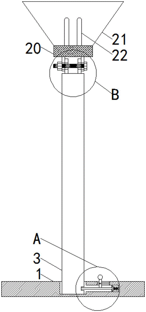
图1为本实用新型结构剖视图;Fig. 1 is the structural sectional view of the utility model;
图2为本实用新型图1中A的局部放大图;Fig. 2 is a partial enlarged view of A in Fig. 1 of the utility model;
图3为本实用新型图1中B的局部放大图。FIG. 3 is a partial enlarged view of B in FIG. 1 of the present utility model.
图中:1-灯具底座、2-放置槽、3-灯柱、4-卡槽、5-卡杆、6-活动杆、 7-滑块、8-通孔一、9-滑槽、10-弹簧、11-压块、12-限位块、13-连接条一、 14-通孔二、15-连接条二、16-通孔三、17-螺纹杆、18-转盘、19-螺栓、20- 灯罩底座、21-灯罩、22-灯管、23-活动槽。In the picture: 1-lamp base, 2-placement slot, 3-lamp post, 4-card slot, 5-bar, 6-movable rod, 7-slider, 8-through hole one, 9-chute, 10 -spring, 11-pressing block, 12-limiting block, 13-connecting strip one, 14-through hole two, 15-connecting strip two, 16-through hole three, 17-threaded rod, 18-turntable, 19-bolt , 20- lampshade base, 21-lampshade, 22-lamp tube, 23-activity slot.
具体实施方式Detailed ways
下面将结合本实用新型实施例中的附图,对本实用新型实施例中的技术方案进行清楚、完整地描述,显然,所描述的实施例仅仅是本实用新型一部分实施例,而不是全部的实施例。基于本实用新型中的实施例,本领域普通技术人员在没有做出创造性劳动前提下所获得的所有其他实施例,都属于本实用新型保护的范围。The technical solutions in the embodiments of the present utility model will be clearly and completely described below with reference to the accompanying drawings in the embodiments of the present utility model. Obviously, the described embodiments are only a part of the embodiments of the present utility model, rather than all the implementations. example. Based on the embodiments of the present invention, all other embodiments obtained by those of ordinary skill in the art without creative work fall within the protection scope of the present invention.
请参阅图1-3,可调节灯源照射角度的室内设计落地灯具,包括灯具底座 1,灯具底座1的底部开设有防滑纹路,使整个灯具在摆放使用时,稳定性更强,使灯具更加合理,灯具底座1的顶部表面开设有放置槽2,放置槽2的内壁右侧开设有活动槽23,活动槽23的内壁上下两侧均固定连接有限位块12,通过限位块12的作用,从而达到了限制卡杆5活动范围的效果,起到一定的保护作用,放置槽2的内部活动连接有灯柱3,灯柱3的右侧开设有卡槽4,卡槽4的内部卡接有卡杆5,卡杆5的右侧固定连接有压块11,压块11的右侧固定连接有弹簧10,弹簧10的底部与活动槽23固定连接,通过弹簧10与压块11的配合使用,从而达到了弹簧10可以通过压块11将张力传导给卡杆 5的效果,灯具底座1的顶部开设有通孔一8,通孔一8的内壁内部开设有滑槽9,滑槽9的内部滑动连接有滑块7,滑块7的一侧固定连接有活动杆6,活动杆6的底部与卡杆5固定连接,通过滑块7、滑槽9、活动杆6与卡杆5 的配合使用,从而达到了使用者可以通过移动活动杆6带动卡杆5进行移动的效果,灯柱3的顶部固定连接有连接条一13,连接条一13的内部开设有通孔二14,连接条一13的一侧活动连接有连接条二15,连接条二15的内部开设有通孔三16,通孔二14与通孔三16的内部均套接有螺纹杆17,螺纹杆17 的右侧固定连接有转盘18,螺纹杆17的左侧螺纹连接有螺栓19,通过螺纹杆17、转盘18与螺栓19的配合使用,从而达到了可以固定连接条一13与连接条二15的效果,通孔二14与通孔三16的直径大小一致,且均大于螺纹杆 17的直径,从而使螺纹杆17可以从通孔二14与通孔三16中穿过,连接条二 15的顶部固定连接有灯罩底座20,灯罩底座20的顶部分别固定连接有灯罩 21和灯管22。Please refer to Figure 1-3, the indoor design floor lamps with adjustable light source illumination angle, including the
工作原理:当使用者要拆卸灯具时,首先,拉动活动杆6向远离放置槽2 的方向移动,活动杆6带动卡杆5向远离放置槽2的方向移动,卡杆5脱离卡槽4,然后使用者拔出灯柱3即可达到拆卸的效果,当需要安装时,拉动活动杆6向远离放置槽2的方向移动,活动杆6带动卡杆5向远离放置槽2的方向移动,然后使用者将灯柱3放入放置槽2中,灯柱3接触到放置槽2的底部时松开活动杆6,此时,弹簧10具有张力,弹簧10带动压块11向靠近放置槽2的方向移动,压块11带动卡杆5向远离放置槽2的方向移动,然后卡杆5插入灯柱3的卡槽4中,并完成固定,从而达到了方便拆卸与安装的效果,当使用者想要调节灯管22的角度时,固定螺栓19,然后逆时针转动转盘18,使连接条一13与连接条二15不再固定,然后再根据使用者的意愿将灯罩21调节到合适角度,调解过后,固定螺栓19,然后顺时针转动转盘18,使连接条一13与连接条二15固定,从而达到了可以根据需要调节灯管角度的效果。Working principle: When the user wants to disassemble the lamp, first, pull the
综上所述,该可调节灯源照射角度的室内设计落地灯具,通过灯柱3的顶部固定连接有连接条一13,连接条一13的内部开设有通孔二14,连接条一13的一侧活动连接有连接条二15,连接条二15的内部开设有通孔三16,连接条二15的顶部固定连接有灯罩底座20,灯罩底座20的顶部分别固定连接有灯罩21和灯管22,通孔二14与通孔三16的内部均套接有螺纹杆17,螺纹杆17的右侧固定连接有转盘18,螺纹杆17的左侧螺纹连接有螺栓19,通过螺纹杆17、转盘18与螺栓19的配合使用,从而达到了可以根据需要调节灯管角度的效果,通过灯具底座1的顶部表面开设有放置槽2,放置槽2的内壁右侧开设有活动槽23,放置槽2的内部活动连接有灯柱3,灯柱3的右侧开设有卡槽4,卡槽4的内部卡接有卡杆5,卡杆5的右侧固定连接有压块 11,灯具底座1的顶部开设有通孔一8,通孔一8的内壁内部开设有滑槽9,滑槽9的内部滑动连接有滑块7,滑块7的一侧固定连接有活动杆6,活动杆 6的底部与卡杆5固定连接,通过卡槽4、卡杆5、滑块7、滑槽9、活动杆6 与弹簧10的配合使用,从而达到了方便拆卸与安装的效果。To sum up, the interior design floor lamp with adjustable illumination angle of the light source is fixedly connected with the connecting
尽管已经示出和描述了本实用新型的实施例,对于本领域的普通技术人员而言,可以理解在不脱离本实用新型的原理和精神的情况下可以对这些实施例进行多种变化、修改、替换和变型,本实用新型的范围由所附权利要求及其等同物限定。Although the embodiments of the present invention have been shown and described, it will be understood by those skilled in the art that various changes and modifications can be made to these embodiments without departing from the principles and spirit of the present invention , alternatives and modifications, the scope of the present invention is defined by the appended claims and their equivalents.
Claims (7)
Priority Applications (1)
| Application Number | Priority Date | Filing Date | Title |
|---|---|---|---|
| CN201922220359.0U CN211574833U (en) | 2019-12-12 | 2019-12-12 | Floor lamps for interior design with adjustable light source illumination angle |
Applications Claiming Priority (1)
| Application Number | Priority Date | Filing Date | Title |
|---|---|---|---|
| CN201922220359.0U CN211574833U (en) | 2019-12-12 | 2019-12-12 | Floor lamps for interior design with adjustable light source illumination angle |
Publications (1)
| Publication Number | Publication Date |
|---|---|
| CN211574833U true CN211574833U (en) | 2020-09-25 |
Family
ID=72535918
Family Applications (1)
| Application Number | Title | Priority Date | Filing Date |
|---|---|---|---|
| CN201922220359.0U Expired - Fee Related CN211574833U (en) | 2019-12-12 | 2019-12-12 | Floor lamps for interior design with adjustable light source illumination angle |
Country Status (1)
| Country | Link |
|---|---|
| CN (1) | CN211574833U (en) |
-
2019
- 2019-12-12 CN CN201922220359.0U patent/CN211574833U/en not_active Expired - Fee Related
Similar Documents
| Publication | Publication Date | Title |
|---|---|---|
| CN207179312U (en) | A kind of adjustable student's desk lamp of multifunctional angular | |
| CN203656819U (en) | Lampshade adjusting lighting range | |
| CN207378589U (en) | A stable desk lamp | |
| CN2503330Y (en) | Multipurpose lighting device | |
| CN210179557U (en) | Environment artistic lamp | |
| CN210771577U (en) | Lighting device for construction engineering construction site | |
| CN206093738U (en) | Double -end LED wall lamp | |
| CN209431167U (en) | A kind of desk lamp of adjusting lighting angle | |
| CN206514257U (en) | A kind of Anti-glare LED lamp of modularity military project level radiating | |
| CN204005486U (en) | A kind of Table lamp structure | |
| CN206555948U (en) | Lamp bracket and light fixture | |
| CN206300133U (en) | A multifunctional table lamp | |
| CN210511164U (en) | Lighting device for multi-scene use | |
| CN223795134U (en) | LED lamp bead with adjustable focal length and variable light effect | |
| CN207990398U (en) | A kind of light is to adjustable energy-saving LED downlight | |
| CN210740199U (en) | Novel multifunctional desk lamp | |
| CN223795157U (en) | Square lamp convenient for replacing lampshade | |
| CN201964149U (en) | Torch type table lamp | |
| CN214840335U (en) | Adjustable light for indoor lighting | |
| CN211040643U (en) | Anti-dazzle L ED down lamp | |
| CN218864127U (en) | Efficient heat dissipation type LED energy-saving lighting device | |
| CN213955116U (en) | Waterproof outdoor lamp | |
| CN202392659U (en) | Desk lamp | |
| CN218820028U (en) | Lamp mounting base | |
| CN202992841U (en) | Retractable folding desk lamp |
Legal Events
| Date | Code | Title | Description |
|---|---|---|---|
| GR01 | Patent grant | ||
| GR01 | Patent grant | ||
| TR01 | Transfer of patent right |
Effective date of registration: 20220705 Address after: 430000 zone B4, No. 1 Ruian street, Nanhu garden, Wuchang District, Wuhan City, Hubei Province (Nanhu Street maker space) Patentee after: Wuhan Minchuang Technology Engineering Co.,Ltd. Address before: 3 / F 306-1, building 2, Haichuang science and technology center, Cangqian street, Yuhang District, Hangzhou City, Zhejiang Province Patentee before: Hangzhou chengmeng Asset Management Co.,Ltd. |
|
| TR01 | Transfer of patent right | ||
| CF01 | Termination of patent right due to non-payment of annual fee |
Granted publication date: 20200925 |
|
| CF01 | Termination of patent right due to non-payment of annual fee |