CN211564157U - Stamping die for automobile fastener - Google Patents
Stamping die for automobile fastener Download PDFInfo
- Publication number
- CN211564157U CN211564157U CN202020058470.4U CN202020058470U CN211564157U CN 211564157 U CN211564157 U CN 211564157U CN 202020058470 U CN202020058470 U CN 202020058470U CN 211564157 U CN211564157 U CN 211564157U
- Authority
- CN
- China
- Prior art keywords
- die
- main body
- groove
- automobile fastener
- piece
- Prior art date
- Legal status (The legal status is an assumption and is not a legal conclusion. Google has not performed a legal analysis and makes no representation as to the accuracy of the status listed.)
- Expired - Fee Related
Links
- 238000004080 punching Methods 0.000 claims description 16
- 239000000463 material Substances 0.000 description 6
- 229910000831 Steel Inorganic materials 0.000 description 5
- 229910045601 alloy Inorganic materials 0.000 description 5
- 239000000956 alloy Substances 0.000 description 5
- 239000010959 steel Substances 0.000 description 5
- 229910001315 Tool steel Inorganic materials 0.000 description 3
- 238000004519 manufacturing process Methods 0.000 description 3
- OKTJSMMVPCPJKN-UHFFFAOYSA-N Carbon Chemical compound [C] OKTJSMMVPCPJKN-UHFFFAOYSA-N 0.000 description 2
- VYZAMTAEIAYCRO-UHFFFAOYSA-N Chromium Chemical compound [Cr] VYZAMTAEIAYCRO-UHFFFAOYSA-N 0.000 description 2
- 229910052799 carbon Inorganic materials 0.000 description 2
- 229910052804 chromium Inorganic materials 0.000 description 2
- 239000011651 chromium Substances 0.000 description 2
- 229910000906 Bronze Inorganic materials 0.000 description 1
- 229910001339 C alloy Inorganic materials 0.000 description 1
- 229910000997 High-speed steel Inorganic materials 0.000 description 1
- HCHKCACWOHOZIP-UHFFFAOYSA-N Zinc Chemical compound [Zn] HCHKCACWOHOZIP-UHFFFAOYSA-N 0.000 description 1
- 230000004075 alteration Effects 0.000 description 1
- 229910052782 aluminium Inorganic materials 0.000 description 1
- XAGFODPZIPBFFR-UHFFFAOYSA-N aluminium Chemical compound [Al] XAGFODPZIPBFFR-UHFFFAOYSA-N 0.000 description 1
- -1 and cemented carbide Substances 0.000 description 1
- 230000009286 beneficial effect Effects 0.000 description 1
- 239000010974 bronze Substances 0.000 description 1
- KUNSUQLRTQLHQQ-UHFFFAOYSA-N copper tin Chemical compound [Cu].[Sn] KUNSUQLRTQLHQQ-UHFFFAOYSA-N 0.000 description 1
- 238000010586 diagram Methods 0.000 description 1
- 238000009434 installation Methods 0.000 description 1
- 230000003993 interaction Effects 0.000 description 1
- 229910052751 metal Inorganic materials 0.000 description 1
- 239000002184 metal Substances 0.000 description 1
- 238000000034 method Methods 0.000 description 1
- 238000012986 modification Methods 0.000 description 1
- 230000004048 modification Effects 0.000 description 1
- 229910052755 nonmetal Inorganic materials 0.000 description 1
- 239000002861 polymer material Substances 0.000 description 1
- 238000003825 pressing Methods 0.000 description 1
- 238000003672 processing method Methods 0.000 description 1
- 239000011265 semifinished product Substances 0.000 description 1
- 238000006467 substitution reaction Methods 0.000 description 1
- 239000011701 zinc Substances 0.000 description 1
- 229910052725 zinc Inorganic materials 0.000 description 1
Images

Landscapes
- Punching Or Piercing (AREA)
Abstract
The utility model discloses an automobile fastener stamping die, which belongs to the technical field of die stamping, and comprises a die main body, wherein two sides of the top of the die main body are connected with a support column, one side of the support column is provided with a chute, the inside of the chute is provided with a slide block, one side of the slide block is connected with a connecting piece, one side of the connecting piece is connected with an upper die base, the inside of the die main body is provided with a cylinder, the automobile fastener stamping die is provided with a groove, a second spring, a top plate and a top piece, the top of the groove is connected with the top plate through the second spring, when a user stamps an automobile fastener, the stamped automobile fastener can be ejected through the top piece and the second spring, the problem that the automobile fastener is difficult to be clamped in the automobile fastener stamping die and is difficult to be taken out after the stamping of, the working efficiency of the stamping die for the automobile fastener is improved.
Description
Technical Field
The utility model relates to a mould punching press technical field specifically is an automobile fastener stamping die.
Background
The stamping die is a special process equipment for processing materials (metal or nonmetal) into parts (or semi-finished products) in cold stamping processing, called as a cold stamping die (commonly called as a cold stamping die), stamping is a pressure processing method for obtaining required parts by applying pressure to the materials by using a die arranged on a press machine at room temperature to separate or plastically deform the materials, wherein the materials for manufacturing the stamping die comprise steel, hard alloy, steel-bonded hard alloy, zinc-based alloy, low-melting-point alloy, aluminum bronze, high polymer material and the like, the majority of the materials for manufacturing the stamping die mainly comprise the steel, and the types of the commonly used die working part materials comprise: carbon tool steel, low alloy tool steel, high carbon high chromium or medium chromium tool steel, medium carbon alloy steel, high speed steel, base steel, and cemented carbide, steel bonded cemented carbide, and the like.
Present automobile fastener stamping die, many structures are comparatively complicated greatly, thereby after the punching press is accomplished to the mould, easily with automobile fastener card in automobile fastener stamping die, be difficult to take out, lead to the staff to use inconvenient and convenient, production efficiency has been reduced easily, and present automobile fastener stamping die, the user often is difficult to highly controlling the punching press, influence automobile fastener stamping die's work efficiency easily, also lead to the user in the use, be difficult to guarantee automobile fastener stamping die's stability.
SUMMERY OF THE UTILITY MODEL
An object of the utility model is to provide an automobile fastener stamping die to propose in solving above-mentioned background art easily with automobile fastener card in automobile fastener stamping die, be difficult to take out, highly be difficult to the problem of controlling of punching press.
In order to achieve the above object, the utility model provides a following technical scheme: the utility model provides an automotive fastener stamping die, includes the mould main part, the top both sides of mould main part are connected with the support column, the spout has been seted up to one side of support column, the inside of spout is provided with the slider, one side of slider is connected with the connecting piece, one side of connecting piece is connected with the upper die base, the internally mounted of mould main part has the cylinder, the output of cylinder is connected with the piston rod, the bottom intermediate junction of upper die base has the push rod, the bottom of push rod is connected with the installed part, the bottom of installed part is connected with joint spare, the bottom of joint spare is connected with the drift, be fixed with the fixed plate in the middle of the top of mould main part, set up flutedly in the middle of the top of fixed plate, there is the roof at the.
Preferably, the number of the cylinders is two, and one end of the piston rod extends to the inside of the upper die holder.
Preferably, the number of the push rods is two, the two push rods are symmetrically arranged along the central line of the transverse shaft of the die main body, and the outer surfaces of the two push rods are provided with first springs.
Preferably, an operation panel is disposed on an outer surface of the mold main body, and the operation panel is electrically connected to the cylinder.
Preferably, the upper die base is arranged in a lifting mode with the die main body through a sliding block, a sliding groove and an air cylinder.
Preferably, the groove is in a shape like a Chinese character 'ji', and the groove is matched with the top plate.
Preferably, the punch is adapted to the fixing plate.
Compared with the prior art, the beneficial effects of the utility model are that: the automobile fastener stamping die is provided with a groove, a second spring, a top plate and a jacking piece, the groove is arranged at the top of a fixed plate, the top of the groove is connected with the top plate through the second spring, when a user stamps an automobile fastener, the stamped automobile fastener can be ejected out through the jacking piece and the second spring, the problem that the automobile fastener is difficult to clamp in the automobile fastener stamping die and difficult to take out after the die is stamped is avoided, the working efficiency of the automobile fastener stamping die is improved, meanwhile, the automobile fastener stamping die is further provided with an air cylinder, an operation panel, a sliding chute and a sliding block, the sliding chute is formed in one side of a supporting column, the sliding block is arranged in the sliding chute and connected with an upper die holder, and when the user uses the automobile fastener stamping die, the air cylinder can be operated through the operation panel, so that the height of the upper die holder is adjusted, the user of being convenient for more controls the height of punching press, also makes this kind of automobile fastener stamping die more stable.
Drawings
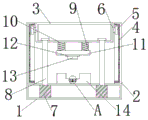
FIG. 1 is a schematic structural view of the present invention;
FIG. 2 is a schematic view of the main structure of the mold of the present invention;
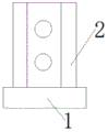
FIG. 3 is a schematic side view of the mold body of the present invention;
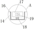
fig. 4 is a schematic diagram of a partially enlarged structure of the present invention a.
In the figure: 1. a mold body; 2. a support pillar; 3. an upper die holder; 4. a chute; 5. a slider; 6. a connecting member; 7. a cylinder; 8. a piston rod; 9. a first spring; 10. a push rod; 11. a mounting member; 12. a clamping piece; 13. a punch; 14. a fixing plate; 15. an operation panel; 16. a groove; 17. a top plate; 18. a second spring; 19. a top piece.
Detailed Description
The technical solutions in the embodiments of the present invention will be described clearly and completely with reference to the accompanying drawings in the embodiments of the present invention, and it is obvious that the described embodiments are only some embodiments of the present invention, not all embodiments. Based on the embodiments in the present invention, all other embodiments obtained by a person skilled in the art without creative work belong to the protection scope of the present invention.
In the present invention, unless otherwise expressly stated or limited, the terms "disposed," "mounted," "connected," "fixed," "sleeved," and the like are to be construed broadly, e.g., as either a fixed connection, a removable connection, or an integral part; can be mechanically or electrically connected; the two elements may be connected directly or indirectly through an intermediate medium, and the two elements may be connected internally or in an interaction relationship, and a person skilled in the art can understand the specific meaning of the above terms in the present invention according to specific situations.
Referring to fig. 1-4, the present invention provides a technical solution: a stamping die for automobile fasteners comprises a die main body 1, a supporting column 2, an upper die base 3, a sliding groove 4, a sliding block 5, a connecting piece 6, a cylinder 7, a piston rod 8, a first spring 9, a push rod 10, an installation piece 11, a clamping piece 12, a punch 13, a fixing plate 14, an operation panel 15, a groove 16, a top plate 17, a second spring 18 and a top piece 19, wherein the supporting column 2 is connected to two sides of the top of the die main body 1, the sliding groove 4 is formed in one side of the supporting column 2, the sliding block 5 is arranged inside the sliding groove 4, the connecting piece 6 is connected to one side of the sliding block 5, the upper die base 3 is connected to one side of the connecting piece 6, the cylinder 7 is arranged inside the die main body 1, the output end of the cylinder 7 is connected with the piston rod 8, the push rod 10 is connected to the middle of the bottom of the upper, a fixing plate 14 is fixed in the middle of the top of the die body 1, a groove 16 is formed in the middle of the top of the fixing plate 14, the top of the groove 16 is connected with a top plate 17 through a second spring 18, a jacking piece 19 is arranged on the outer surface of the top plate 17, and the automobile fastener is ejected out through the jacking piece 19.
Referring to fig. 2, two cylinders 7 are provided, one end of a piston rod 8 extends into the upper die holder 3, and the two cylinders 7 can be operated through an operation panel 15, so that the height of the upper die holder 3 is adjusted, a user can more conveniently control the punching height, two push rods 10 are provided, the two push rods 10 are symmetrically arranged along the central line of the transverse shaft of the die main body 1, the outer surfaces of the two push rods 10 are provided with first springs 9, the punch 13 is buffered by using the first springs 9, and the practicability of the punching die for the automobile fastener is enhanced.
Referring to fig. 1-2, an operation panel 15 is disposed on an outer surface of the die main body 1, and the operation panel 15 is electrically connected to the cylinder 7, so that a user can operate the cylinder 7 by using the operation panel 15, the upper die base 3 is lifted up and down from the die main body 1 by the slider 5, the chute 4, and the cylinder 7, and when the user is using the die, the cylinder 7 can be operated by using the operation panel 15, so that the height of the upper die base 3 can be adjusted, and the user can control the stamping height more conveniently.
Referring to fig. 4, the groove 16 is in a shape of a Chinese character 'ji', the groove 16 is matched with the top plate 17, a user punches the automobile fastener by using the cylinder 7, the punch 13 is matched with the fixing plate 14, and when the user uses the automobile fastener punching die, the cylinder 7 can be operated by the operation panel 15, so that the height of the upper die holder 3 is adjusted, the punching height can be controlled by the user more conveniently, and the automobile fastener punching die is more stable.
The working principle is as follows: firstly, a user places the stamping die for the automobile fastener on a horizontal desktop, one side of a supporting column 2 is provided with a sliding groove 4, a sliding block 5 is arranged inside the sliding groove 4, the sliding block 5 is connected with an upper die base 3, when the user is in use, the air cylinder 7 can be operated through the operation panel 15, so as to adjust the height of the upper die holder 3, the user places the automobile fastener on the fixed plate 14, so as to punch the automobile fastener, and the outer surfaces of the two push rods 10 are respectively provided with a first spring 9, the punch 13 is buffered by using the first spring 9, and by providing a groove 16 at the top of the fixing plate 14, the groove 16 being in the shape of a "d", at the top of the recess 16, a top plate 17 is attached by a second spring 18, which, when the user is stamping the car fastener, the stamped automotive fastener may be ejected through the use of a top piece 19 and a second spring 18.
Although embodiments of the present invention have been shown and described, it will be appreciated by those skilled in the art that changes, modifications, substitutions and alterations can be made in these embodiments without departing from the principles and spirit of the invention, the scope of which is defined in the appended claims and their equivalents.
Claims (7)
1. The utility model provides an automobile fastener stamping die, includes mould main part (1), its characterized in that: the die is characterized in that supporting columns (2) are connected to two sides of the top of the die main body (1), a sliding groove (4) is formed in one side of each supporting column (2), a sliding block (5) is arranged inside each sliding groove (4), a connecting piece (6) is connected to one side of each sliding block (5), an upper die base (3) is connected to one side of each connecting piece (6), an air cylinder (7) is installed inside the die main body (1), an output end of each air cylinder (7) is connected with a piston rod (8), a push rod (10) is connected to the middle of the bottom of each upper die base (3), an installing piece (11) is connected to the bottom of each push rod (10), a clamping piece (12) is connected to the bottom of each installing piece (11), a punch (13) is connected to the bottom of each clamping piece (12), a fixing plate (14) is fixed to the middle of, the top of the groove (16) is connected with a top plate (17) through a second spring (18), and the outer surface of the top plate (17) is provided with a top piece (19).
2. The automotive fastener punching die of claim 1, wherein: the two cylinders (7) are arranged, and one end of the piston rod (8) extends into the upper die holder (3).
3. The automotive fastener punching die of claim 1, wherein: the die is characterized in that the number of the push rods (10) is two, the push rods (10) are symmetrically arranged along the central line of a transverse shaft of the die main body (1), and first springs (9) are arranged on the outer surfaces of the push rods (10).
4. The automotive fastener punching die of claim 1, wherein: the outer surface of the die main body (1) is provided with an operation panel (15), and the operation panel (15) is electrically connected with the air cylinder (7).
5. The automotive fastener punching die of claim 1, wherein: the upper die base (3) is arranged in a lifting mode with the die main body (1) through a sliding block (5), a sliding groove (4) and a cylinder (7).
6. The automotive fastener punching die of claim 1, wherein: the groove (16) is in a shape like a Chinese character 'ji', and the groove (16) is matched with the top plate (17).
7. The automotive fastener punching die of claim 1, wherein: the punch (13) is matched with the fixing plate (14).
Priority Applications (1)
| Application Number | Priority Date | Filing Date | Title |
|---|---|---|---|
| CN202020058470.4U CN211564157U (en) | 2020-01-13 | 2020-01-13 | Stamping die for automobile fastener |
Applications Claiming Priority (1)
| Application Number | Priority Date | Filing Date | Title |
|---|---|---|---|
| CN202020058470.4U CN211564157U (en) | 2020-01-13 | 2020-01-13 | Stamping die for automobile fastener |
Publications (1)
| Publication Number | Publication Date |
|---|---|
| CN211564157U true CN211564157U (en) | 2020-09-25 |
Family
ID=72555733
Family Applications (1)
| Application Number | Title | Priority Date | Filing Date |
|---|---|---|---|
| CN202020058470.4U Expired - Fee Related CN211564157U (en) | 2020-01-13 | 2020-01-13 | Stamping die for automobile fastener |
Country Status (1)
| Country | Link |
|---|---|
| CN (1) | CN211564157U (en) |
Cited By (1)
| Publication number | Priority date | Publication date | Assignee | Title |
|---|---|---|---|---|
| CN112605210A (en) * | 2020-12-24 | 2021-04-06 | 谢志军 | Safety device for debugging stamping die |
-
2020
- 2020-01-13 CN CN202020058470.4U patent/CN211564157U/en not_active Expired - Fee Related
Cited By (1)
| Publication number | Priority date | Publication date | Assignee | Title |
|---|---|---|---|---|
| CN112605210A (en) * | 2020-12-24 | 2021-04-06 | 谢志军 | Safety device for debugging stamping die |
Similar Documents
| Publication | Publication Date | Title |
|---|---|---|
| CN207628999U (en) | A kind of binder flange body | |
| CN207592661U (en) | A kind of stamping die cylinder discharging structure for stamping parts of automobile | |
| CN2865900Y (en) | A U-type thick plate bending mold | |
| CN201500743U (en) | Complex side piercing and shaping composite die of vehicle running board supporting seat | |
| CN218015247U (en) | Die for stamping aluminum profiles | |
| CN202114131U (en) | Hooking stamping mechanism of stamping die for automotive panels | |
| CN2197146Y (en) | Drilling model on an aluminium door-fram | |
| CN216226479U (en) | Positioning device for plate stamping | |
| CN210387221U (en) | Continuous stamping die of inner support of automobile door | |
| CN212285564U (en) | An easy-to-replace mold structure | |
| CN216065055U (en) | Stamping device for port machine track pressing plate | |
| CN213003918U (en) | Fixing device convenient to cutting of car abnormal shape work piece | |
| CN221312155U (en) | Quick installation and disassembly hardware stamping die | |
| CN222344000U (en) | Stamping die | |
| CN212494798U (en) | Cold stamping forming die for chassis of heavy truck | |
| CN223997114U (en) | Cutter processing stamping die | |
| CN221289246U (en) | Mould convenient to adjustment shaping clearance | |
| CN210023439U (en) | Multi-station rapid forming tool for copper insert of sensor | |
| CN210966612U (en) | Reinforced automobile mold | |
| CN212704014U (en) | Die mechanism capable of performing secondary stamping operation | |
| CN218134563U (en) | Turnover mechanism of stamping production line | |
| CN218693085U (en) | Automobile shock absorber ware support cut-out press | |
| CN212469422U (en) | Side hole punching die for automobile skylight frame | |
| CN219985958U (en) | Special-shaped stamping part die | |
| CN214488529U (en) | Quick switching die for automobile top cover with or without skylight |
Legal Events
| Date | Code | Title | Description |
|---|---|---|---|
| GR01 | Patent grant | ||
| GR01 | Patent grant | ||
| CF01 | Termination of patent right due to non-payment of annual fee | ||
| CF01 | Termination of patent right due to non-payment of annual fee |
Granted publication date: 20200925 Termination date: 20220113 |