CN211562175U - Automatic dust recovery equipment - Google Patents
Automatic dust recovery equipment Download PDFInfo
- Publication number
- CN211562175U CN211562175U CN201921914057.7U CN201921914057U CN211562175U CN 211562175 U CN211562175 U CN 211562175U CN 201921914057 U CN201921914057 U CN 201921914057U CN 211562175 U CN211562175 U CN 211562175U
- Authority
- CN
- China
- Prior art keywords
- dust
- box
- air inlet
- noise reduction
- recovery equipment
- Prior art date
- Legal status (The legal status is an assumption and is not a legal conclusion. Google has not performed a legal analysis and makes no representation as to the accuracy of the status listed.)
- Expired - Fee Related
Links
- 239000000428 dust Substances 0.000 title claims abstract description 76
- 238000011084 recovery Methods 0.000 title claims abstract description 23
- 229920000742 Cotton Polymers 0.000 claims abstract description 13
- 239000004744 fabric Substances 0.000 claims abstract description 10
- 239000003365 glass fiber Substances 0.000 claims abstract description 10
- 239000000843 powder Substances 0.000 claims abstract description 7
- 239000011148 porous material Substances 0.000 claims 4
- 230000007246 mechanism Effects 0.000 abstract description 27
- 230000009467 reduction Effects 0.000 abstract description 16
- 230000030279 gene silencing Effects 0.000 abstract description 9
- 238000004064 recycling Methods 0.000 abstract description 9
- 230000000694 effects Effects 0.000 abstract description 4
- 238000005507 spraying Methods 0.000 abstract description 4
- 238000001914 filtration Methods 0.000 abstract description 2
- 238000000034 method Methods 0.000 description 7
- 238000010586 diagram Methods 0.000 description 3
- 230000005686 electrostatic field Effects 0.000 description 2
- 230000008569 process Effects 0.000 description 2
- 230000003584 silencer Effects 0.000 description 2
- 239000007921 spray Substances 0.000 description 2
- 230000007480 spreading Effects 0.000 description 2
- 230000009471 action Effects 0.000 description 1
- 238000000889 atomisation Methods 0.000 description 1
- 230000009286 beneficial effect Effects 0.000 description 1
- 230000000903 blocking effect Effects 0.000 description 1
- 238000007664 blowing Methods 0.000 description 1
- 238000010410 dusting Methods 0.000 description 1
- 238000007590 electrostatic spraying Methods 0.000 description 1
- 239000003973 paint Substances 0.000 description 1
- 239000002245 particle Substances 0.000 description 1
- 238000005086 pumping Methods 0.000 description 1
Images


Landscapes
- Filtering Of Dispersed Particles In Gases (AREA)
Abstract
本实用新型涉及静电粉末喷涂技术领域,尤其是指一种粉尘自动回收设备,其包括架体、伸缩风管接头、消音箱、集尘箱、风机、落尘机构以及多个过滤机构,过滤机构经由伸缩风管接头与风机连通;所述消音箱包括箱壳、孔板、消音棉层以及玻纤布层。本实用新型的风机启动对集尘箱抽风,过滤机构对粉尘进行过滤,使得粉尘停留在集尘箱内,当过滤机构上吸附一定量的粉尘,落尘机构对过滤机构吹气,使得吸附在过滤机构的粉尘落下,实现粉尘回收利用,提高粉尘的回收率;消音棉层以及玻纤布层具有良好的降噪性能,消音棉层以及玻纤布层将整个风机包围,能够对风机进行全面消音,对噪音源进行有效的消音降噪,消音降噪效果好。
The utility model relates to the technical field of electrostatic powder spraying, in particular to an automatic dust recovery device, which comprises a frame body, a telescopic air duct joint, a muffler box, a dust collecting box, a fan, a dust dropping mechanism and a plurality of filtering mechanisms. The telescopic air duct joint is communicated with the fan; the silencing box includes a box shell, an orifice plate, a silencing cotton layer and a glass fiber cloth layer. The fan of the utility model starts to draw air to the dust collecting box, and the filter mechanism filters the dust, so that the dust stays in the dust collecting box. The dust of the mechanism falls to realize the dust recycling and improve the dust recovery rate; the sound-absorbing cotton layer and the glass fiber cloth layer have good noise reduction performance. , Effective noise reduction and noise reduction for the noise source, the noise reduction and noise reduction effect is good.
Description
技术领域technical field
本实用新型涉及静电粉末喷涂技术领域,尤其是指一种粉尘自动回收设备。The utility model relates to the technical field of electrostatic powder spraying, in particular to an automatic dust recovery device.
背景技术Background technique
静电喷涂法是以接地的被涂物作为阳极,设备高压电栅作为阴极,静电喷枪接上负高压,在两极间形成高压静电场,阴极产生电晕放电,使喷出的涂料粒子带电,并进一步雾化,按同性相斥,异性相吸的原理,使带电的涂料粒子在静电场的作用下沿电力线方向吸附被涂物,放电后粘附在被涂物上的一种工艺方法。喷粉系统可以对工件表面进行喷制,在工业应用中十分广泛。喷粉系统在对工件喷制过程中会产生粉尘,因此,必须考虑到对粉尘的过滤及回收,防止粉尘污染空气,通常在回收粉尘需要用风机,风机在使用过程中的噪音较大,需要对其进行消音降噪,传统的消音方式是在排风口出安装消音器,此种方式的只能够对排风口处进行局部消音,大部分的噪音依然能够传播到外界,消音降噪效果差。The electrostatic spraying method uses the grounded object to be coated as the anode, the high-voltage grid of the equipment as the cathode, the electrostatic spray gun is connected to a negative high voltage, and a high-voltage electrostatic field is formed between the two poles. And further atomization, according to the principle of repulsion of the same sex and attraction of the opposite sex, a process method that makes the charged paint particles adsorb the coated object along the direction of the electric force under the action of the electrostatic field, and adhere to the coated object after discharge. The powder spraying system can spray the surface of the workpiece and is widely used in industrial applications. The dusting system will generate dust in the process of spraying the workpiece. Therefore, the filtration and recovery of dust must be considered to prevent dust from polluting the air. Usually, a fan is required to recover dust. To muffle and reduce noise, the traditional muffler method is to install a muffler at the exhaust outlet. This method can only partially muffle the exhaust outlet, and most of the noise can still be transmitted to the outside world, and the effect of noise reduction and noise reduction Difference.
发明内容SUMMARY OF THE INVENTION
本实用新型要解决的技术问题是提供一种粉尘自动回收设备,实现粉尘回收利用,对噪音源进行有效的消音降噪,消音降噪效果好。The technical problem to be solved by the utility model is to provide an automatic dust recovery device, which realizes the dust recovery and utilization, and effectively silencing and reducing noise for the noise source, with good sound silencing and noise reduction effect.
为了解决上述技术问题,本实用新型采用如下技术方案:In order to solve the above-mentioned technical problems, the utility model adopts the following technical solutions:
一种粉尘自动回收设备,其包括架体、伸缩风管接头、设置于架体的消音箱、设置于架体的集尘箱、安装于消音箱内部的风机、活动安装于架体的落尘机构以及可拆卸安装于集尘箱内多个过滤机构,所述过滤机构经由伸缩风管接头与风机连通;所述消音箱包括安装于机架的箱壳、设置于箱壳内部的孔板、设置于箱壳与孔板之间的消音棉层以及设置于消音棉层与孔板之间的玻纤布层,所述孔板设有多个通孔。An automatic dust recovery device, which includes a frame body, a telescopic air duct joint, a silencing box arranged on the frame body, a dust collecting box arranged on the frame body, a fan installed inside the silencing box, and a dust dropping mechanism movably installed on the frame body and a plurality of filter mechanisms detachably installed in the dust collecting box, the filter mechanisms are communicated with the fan through the telescopic air duct joint; The sound-absorbing cotton layer between the box shell and the orifice plate and the glass fiber cloth layer arranged between the sound-absorbing cotton layer and the orifice plate, and the orifice plate is provided with a plurality of through holes.
进一步地,所述回收设备还包括与集尘箱连通的进风管道,进风管道贯穿消音箱与集尘箱连通,进风管道设有弯折进风端,弯折进风端的进风口显露于消音箱外,进风管道的一端位于消音箱内,进风管道的另一端与集尘箱连通。Further, the recycling equipment also includes an air inlet duct that communicates with the dust collecting box. The air inlet duct runs through the muffler box and communicates with the dust collecting box. The air inlet duct is provided with a bent air inlet end, and the air inlet of the bent air inlet end is exposed. Outside the muffler box, one end of the air inlet duct is located in the muffler box, and the other end of the air inlet duct is communicated with the dust collecting box.
进一步地,所述回收设备还包括安装于集尘箱底部的集尘斗。Further, the recycling equipment further includes a dust collecting hopper installed at the bottom of the dust collecting box.
进一步地,所述集尘斗的底部连通有粉末回收泵。Further, a powder recovery pump is communicated with the bottom of the dust collecting hopper.
进一步地,所述消音箱的顶部设有排风口。Further, the top of the muffler box is provided with an air outlet.
进一步地,所述架体底部安装有多个万向轮支撑脚。Further, a plurality of universal wheel supporting feet are installed on the bottom of the frame body.
本实用新型的有益效果:本实用新型在实际运用中,将带有粉尘的空气导入集尘箱内,风机启动对集尘箱抽风,过滤机构对粉尘进行过滤,使得粉尘停留在集尘箱内,当过滤机构上吸附一定量的粉尘,落尘机构对过滤机构吹气,使得吸附在过滤机构的粉尘落下,实现粉尘回收利用,提高粉尘的回收率;消音棉层以及玻纤布层具有良好的降噪性能,消音棉层以及玻纤布层将整个风机包围,能够对风机进行全面消音,阻隔噪音传播到消音箱外,对噪音源进行有效的消音降噪,消音降噪效果好。Beneficial effects of the utility model: In the practical application of the utility model, the air with dust is introduced into the dust collecting box, the fan is started to draw air into the dust collecting box, and the filter mechanism filters the dust, so that the dust stays in the dust collecting box , When a certain amount of dust is adsorbed on the filter mechanism, the dust-removing mechanism blows air to the filter mechanism, so that the dust adsorbed on the filter mechanism falls, realizes dust recycling, and improves the dust recovery rate; the sound-absorbing cotton layer and the glass fiber cloth layer have good performance. Noise reduction performance, the sound-absorbing cotton layer and the glass fiber cloth layer surround the entire fan, which can completely silence the fan, block the noise from spreading to the outside of the silencer box, and effectively reduce the noise source. The noise reduction effect is good.
附图说明Description of drawings
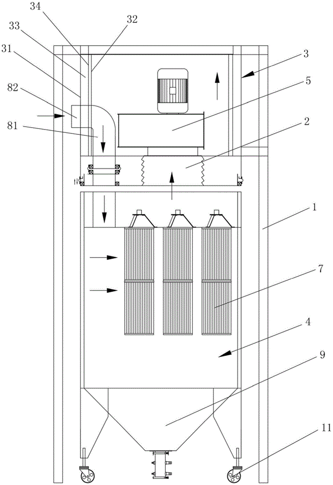
图1为本实用新型的整体结构示意图一。FIG. 1 is a schematic diagram 1 of the overall structure of the present invention.
图2为本实用新型的整体结构示意图二。FIG. 2 is a second schematic diagram of the overall structure of the utility model.
图3为本实用新型的风机、消音箱、排风口和架体的结构示意图。3 is a schematic structural diagram of a fan, a muffler box, an air outlet and a frame of the present invention.
附图标记说明:Description of reference numbers:
1-架体;11-万向轮支撑脚;2-伸缩风管接头;3-消音箱;31-箱壳;32-孔板;33-消音棉层;34-玻纤布层;35-排风口;4-集尘箱;5-风机;6-落尘机构;7-过滤机构;81-进风管道;82-弯折进风端;9-集尘斗。1-frame body; 11- universal wheel supporting feet; 2- telescopic air duct joint; 3- muffler box; 31- box shell; 32- orifice plate; 33- muffler cotton layer; 34- glass fiber cloth layer; 35- Air outlet; 4-dust box; 5-fan; 6-dust drop mechanism; 7-filter mechanism; 81-air inlet pipe; 82-bent air inlet end; 9-dust bucket.
具体实施方式Detailed ways
为了便于本领域技术人员的理解,下面结合实施例与附图对本实用新型作进一步的说明,实施方式提及的内容并非对本实用新型的限定。In order to facilitate the understanding of those skilled in the art, the present invention will be further described below with reference to the embodiments and the accompanying drawings, and the contents mentioned in the embodiments are not intended to limit the present invention.
如图1至图3所示,本实用新型提供的一种粉尘自动回收设备,其包括架体1、伸缩风管接头2、设置于架体1的消音箱3、设置于架体1的集尘箱4、安装于消音箱3内部的风机5、活动安装于架体1的落尘机构6以及可拆卸安装于集尘箱4内多个过滤机构7,过滤机构7能够灵活更换,所述过滤机构7经由伸缩风管接头2与风机5连通;所述消音箱3包括安装于机架1的箱壳31、设置于箱壳31内部的孔板32、设置于箱壳31与孔板32之间的消音棉层33以及设置于消音棉层33与孔板32之间的玻纤布层34,所述孔板32设有多个通孔(图中未示出)。As shown in FIG. 1 to FIG. 3 , an automatic dust recovery device provided by the present invention includes a
实际运用中,带有粉尘的空气导入集尘箱4内,风机5启动对过滤机构7正向抽风,过滤机构7对粉尘进行过滤,使得粉尘停留在集尘箱4内,当过滤机构7上吸附一定量的粉尘,落尘机构6对过滤机构7反向吹气,使得吸附在过滤机构7外表面的粉尘落下,实现粉尘回收利用,提高粉尘的回收率;伸缩风管接头2可实现定向排风,使得过滤机构7与风机5灵活装配连接;消音棉层33以及玻纤布层34具有良好的降噪性能,消音棉层33以及玻纤布层34将整个风机5包围,能够对风机进行全面消音,阻隔噪音传播到消音箱3外,对噪音源进行有效的消音降噪,消音降噪效果好。In actual application, the air with dust is introduced into the
本实施例中,所述回收设备还包括与集尘箱4连通的进风管道81,进风管道81贯穿消音箱3与集尘箱4连通,进风管道81设有弯折进风端82,弯折进风端82的进风口显露于消音箱3外,进风管道81的一端位于消音箱3内,进风管道81的另一端与集尘箱4连通。具体的,所述弯折进风端82与外界的鼓风机构连通,进风处也会有进风噪音,将进风管道81的进风端设置于消音箱3内,能够对进风噪音进行有效的消音降噪,消音降噪效果好。In this embodiment, the recycling device further includes an
本实施例中,所述回收设备还包括安装于集尘箱4底部的集尘斗9,所述集尘斗9用于收集粉尘。所述集尘斗9的底部连通有粉末回收泵(图中未示出),粉末回收泵用于将集尘斗9内的粉尘泵出并回收利用。In this embodiment, the recycling equipment further includes a dust collecting
本实施例中,所述消音箱3的顶部设有排风口35,干净的空气经由排风口35排出外界。In this embodiment, the top of the
本实施例中,所述架体1底部安装有多个万向轮支撑脚11,万向轮支撑脚11便于将整个回收设备移动,使得移动快捷省力。In this embodiment, a plurality of universal
本实施例中的所有技术特征均可根据实际需要而进行自由组合。All the technical features in this embodiment can be freely combined according to actual needs.
上述实施例为本实用新型较佳的实现方案,除此之外,本实用新型还可以其它方式实现,在不脱离本技术方案构思的前提下任何显而易见的替换均在本实用新型的保护范围之内。The above-mentioned embodiments are the preferred implementation solutions of the present invention. In addition, the present invention can also be realized in other ways. Any obvious replacements are within the protection scope of the present invention without departing from the concept of the technical solution. Inside.
Claims (6)
Priority Applications (1)
| Application Number | Priority Date | Filing Date | Title |
|---|---|---|---|
| CN201921914057.7U CN211562175U (en) | 2019-11-07 | 2019-11-07 | Automatic dust recovery equipment |
Applications Claiming Priority (1)
| Application Number | Priority Date | Filing Date | Title |
|---|---|---|---|
| CN201921914057.7U CN211562175U (en) | 2019-11-07 | 2019-11-07 | Automatic dust recovery equipment |
Publications (1)
| Publication Number | Publication Date |
|---|---|
| CN211562175U true CN211562175U (en) | 2020-09-25 |
Family
ID=72532164
Family Applications (1)
| Application Number | Title | Priority Date | Filing Date |
|---|---|---|---|
| CN201921914057.7U Expired - Fee Related CN211562175U (en) | 2019-11-07 | 2019-11-07 | Automatic dust recovery equipment |
Country Status (1)
| Country | Link |
|---|---|
| CN (1) | CN211562175U (en) |
Cited By (1)
| Publication number | Priority date | Publication date | Assignee | Title |
|---|---|---|---|---|
| CN118304717A (en) * | 2024-03-05 | 2024-07-09 | 美天为华环境工程(山东)有限公司 | Low-voltage pulse cloth bag dust collector |
-
2019
- 2019-11-07 CN CN201921914057.7U patent/CN211562175U/en not_active Expired - Fee Related
Cited By (2)
| Publication number | Priority date | Publication date | Assignee | Title |
|---|---|---|---|---|
| CN118304717A (en) * | 2024-03-05 | 2024-07-09 | 美天为华环境工程(山东)有限公司 | Low-voltage pulse cloth bag dust collector |
| CN118304717B (en) * | 2024-03-05 | 2024-09-10 | 美天为华环境工程(山东)有限公司 | Low-voltage pulse cloth bag dust collector |
Similar Documents
| Publication | Publication Date | Title |
|---|---|---|
| CN206853380U (en) | A kind of construction site dust arrester | |
| CN106492575B (en) | A kind of efficient central dust-removing system | |
| CN211373279U (en) | A high-efficiency submerged arc furnace soot collection device | |
| WO2021008460A1 (en) | Device for removing dust from flue gas using water mist | |
| CN209679726U (en) | A furniture spray paint waste gas collection device | |
| CN204395631U (en) | A kind of dry type overlay film demister | |
| CN208742188U (en) | A kind of cleaner with decrease of noise functions | |
| CN211513920U (en) | A kind of dust discharge device of electric equipment dust collector | |
| CN208244350U (en) | A kind of exhaust-gas treatment conveying device for environmental protection equipment | |
| CN211563474U (en) | Self-cleaning spray room | |
| CN210131504U (en) | Dust removal equipment for mechanical automation processing workshop | |
| CN213495557U (en) | Purifier that exhaust-gas treatment used sprays paint | |
| CN211539855U (en) | An electronic maintenance soldering iron welding waste fume discharge system | |
| CN212068171U (en) | Building engineering construction dust collector | |
| CN211913209U (en) | A textile dust collection device for fabric textiles | |
| CN209706261U (en) | A kind of cooling dedusting exhaust system | |
| CN208642197U (en) | A kind of novel environment friendly cyclone dust collector | |
| CN218011918U (en) | A waste gas collection and treatment device | |
| CN219186302U (en) | Dust-containing waste gas treatment pipe | |
| CN216704720U (en) | Shock attenuation cyclone | |
| CN207648890U (en) | A kind of kitchen ventilator of a variety of Oil sucking devices of band | |
| CN207056785U (en) | The vertical square tube wet electrical dust precipitator of construction | |
| CN214764291U (en) | Heat dissipation system used in closed space | |
| CN218884060U (en) | Fume exhaust device for fume exhaust purification engineering in kitchen | |
| CN205965406U (en) | Exhaust gas treatment equipment for flavours and fragrances production |
Legal Events
| Date | Code | Title | Description |
|---|---|---|---|
| GR01 | Patent grant | ||
| GR01 | Patent grant | ||
| CF01 | Termination of patent right due to non-payment of annual fee |
Granted publication date: 20200925 |
|
| CF01 | Termination of patent right due to non-payment of annual fee |