CN211557960U - Agricultural fertilizing and seeding device - Google Patents
Agricultural fertilizing and seeding device Download PDFInfo
- Publication number
- CN211557960U CN211557960U CN201922416804.0U CN201922416804U CN211557960U CN 211557960 U CN211557960 U CN 211557960U CN 201922416804 U CN201922416804 U CN 201922416804U CN 211557960 U CN211557960 U CN 211557960U
- Authority
- CN
- China
- Prior art keywords
- discharging pipe
- rotating shaft
- seeding
- fixed mounting
- fertilizer
- Prior art date
- Legal status (The legal status is an assumption and is not a legal conclusion. Google has not performed a legal analysis and makes no representation as to the accuracy of the status listed.)
- Active
Links
Images


Abstract
The utility model discloses an agricultural fertilizing and seeding device, comprising a base plate, the top fixed mounting of bottom plate has seeding case and can fertilizer, the bottom fixed mounting of seeding case has first discharging pipe, first discharging pipe is linked together with seeding incasement portion, the bottom fixed mounting of can fertilizer has the second discharging pipe, the second discharging pipe is linked together with can fertilizer is inside, first discharging pipe and second discharging pipe all run through the bottom plate, be equipped with first pivot in the seeding incasement, fixed cover is equipped with first spiral impeller in the first pivot, the bottom of first pivot and first spiral impeller's bottom all extend to in the first discharging pipe, be equipped with the second pivot in the can fertilizer, the equal fixed mounting in both sides of second pivot has six puddlers. The utility model relates to a rationally, the practicality is good, easy operation, seeding fertilization in-process, can bury the work to the soil fluting, seeding, fertilization and earthing and go on simultaneously, improved work efficiency, reduced intensity of labour.
Description
Technical Field
The utility model relates to the technical field of agricultural mechanical equipment, in particular to an agricultural fertilizing and seeding device.
Background
Nowadays, with the development and continuous progress of science and technology, the agricultural planting industry in China is increasingly large in scale, China is a big agricultural country, agriculture is a basic industry for supporting national economic construction and development, and a large amount of crops are required to be planted every year.
However, in the prior art, when crops are planted, generally, a groove is formed in the soil, seeds and chemical fertilizers are scattered, and finally the groove is covered with soil, and the operations are separately performed through the steps, so that the groove forming, sowing, fertilizing and covering with soil cannot be integrally performed, the working time of workers is long, the labor intensity of workers is increased, the labor consumption is high, and the working efficiency is low.
SUMMERY OF THE UTILITY MODEL
The utility model provides a not enough to prior art, the utility model provides an agricultural fertilizing and seeding device has solved and has planted the in-process to crops, can't accomplish to bury work integration going on with ditching slot, seeding, fertilization and earthing, and the operating time that causes the staff is long, has increased workman's intensity of labour, consumes energy many, problem that work efficiency is low.
In order to achieve the above object, the utility model provides a following technical scheme: an agricultural fertilizing and seeding device comprises a bottom plate, wherein a seeding box and a fertilizer box are fixedly mounted at the top of the bottom plate, a first discharging pipe is fixedly mounted at the bottom of the seeding box and communicated with the inside of the seeding box, a second discharging pipe is fixedly mounted at the bottom of the fertilizer box and communicated with the inside of the fertilizer box, the first discharging pipe and the second discharging pipe both penetrate through the bottom plate, a first rotating shaft is arranged in the seeding box, a first spiral impeller is fixedly sleeved on the first rotating shaft, the bottom end of the first rotating shaft and the bottom end of the first spiral impeller both extend into the first discharging pipe, a second rotating shaft is arranged in the fertilizer box, six stirring rods are fixedly mounted on both sides of the second rotating shaft, a second spiral impeller positioned below the stirring rods is fixedly sleeved on the second rotating shaft, the bottom end of the second rotating shaft and the bottom end of the second spiral impeller both extend into the second discharging pipe, a first mounting hole is formed in the inner wall of the top of, the top end of the first rotating shaft penetrates through the first mounting hole, a second mounting hole is formed in the inner wall of the top of the fertilizer box, the top end of the second rotating shaft penetrates through the second mounting hole, belt pulleys are fixedly sleeved on the top end of the first rotating shaft and the top end of the second rotating shaft, the same belt is wound on the two belt pulleys, a motor is fixedly mounted at the top of the sowing box, the output shaft end of the motor is fixedly connected with the top end of the first rotating shaft, a storage battery and a first hydraulic cylinder are fixedly mounted at the top of the bottom plate, a first telescopic rod is fixedly mounted at the output end of the first hydraulic cylinder, a plough head is fixedly mounted at the bottom end of the first telescopic rod, a second hydraulic cylinder is fixedly mounted at the top of the bottom plate, a second telescopic rod is fixedly mounted at the output end of the second hydraulic cylinder, a connecting rod is fixedly mounted at the bottom end of the connecting rod, the bottom fixed mounting of diaphragm has the pole of stirring soil, and the top fixed mounting of slide bar has the spring, and the top of spring and the top inner wall fixed connection of spout have seted up first charge door on the top inner wall of seeding case, have seted up the second charge door on the top inner wall of fertilizer case.
Preferably, the bottom fixed mounting of bottom plate has four support columns, and four support columns are two bisymmetry settings, and the bottom of four support columns is all rotated and is installed the gyro wheel.
Preferably, the top fixed mounting of bottom plate has the riser, and one side fixed mounting that the second pneumatic cylinder was kept away from to the riser has the handrail pole, and the equal fixed mounting in bottom of first discharging pipe and second discharging pipe has the gate valve.
Preferably, the first rotating shaft and the second rotating shaft are fixedly sleeved with bearings, and outer rings of the two bearings are fixedly connected with the inner walls of the first mounting hole and the second mounting hole respectively.
Preferably, the top of the bottom plate is provided with a first through hole and a second through hole, the bottom end of the first telescopic rod penetrates through the first through hole, and the bottom end of the second telescopic rod penetrates through the second through hole.
Preferably, the number of the soil shifting rods is multiple, and the multiple soil shifting rods are arranged at equal intervals.
Preferably, the limiting grooves are formed in the inner walls of the two sides of the sliding groove, the limiting blocks are fixedly mounted on the two sides of the sliding rod, and the two limiting blocks are slidably mounted in the two limiting grooves respectively.
The utility model provides an agricultural fertilizing and seeding device. The method has the following beneficial effects:
(1) the agricultural fertilizing and seeding device comprises a seeding box, a first feed opening, a second feed opening, a plurality of rollers, a first hydraulic cylinder, a second hydraulic cylinder, a connecting rod, a sliding rod, a transverse plate and a plurality of soil stirring rods, wherein a proper amount of crop seeds can be added into the seeding box through the first feed opening, a proper amount of granular fertilizer can be added into the fertilizer box through the second feed opening, the four rollers can push the device to move, the first hydraulic cylinder is started to work, the first telescopic rod pushes the plowshare to move downwards to a proper depth in soil, the first hydraulic cylinder stops working, the second hydraulic cylinder stops working after the soil stirring rods move downwards to contact the ground, the motor drives the first rotating shaft, the belt pulley on the first rotating shaft and the first spiral impeller to rotate at a low speed, and under the transmission action of the belt, the second rotating shaft, the second spiral impeller and twelve stirring rods rotate, the two gate valves are opened, crop seeds in the seeding box are discharged from the first discharging pipe at the uniform speed by utilizing the rotation of the first spiral impeller, granular fertilizers in the fertilizer box are discharged from the second discharging pipe at the uniform speed by utilizing the rotation of the second spiral impeller, and the fertilizers can be uniformly mixed and stirred by utilizing the rotation of the twelve stirring rods.
(2) This agricultural fertilizing and seeding device, promote this equipment at the uniform velocity forward through holding the bar, utilize the ploughshare to set up microscler slot on the soil, the crops seed falls to the ditch inslot from first discharging pipe, granular fertilizer falls to the ditch inslot from the second discharging pipe, utilize a plurality of stirring poles can push away the soil that the slot edge turned out to the ditch inslot, carry out the earthing to crops seed and fertilizer and bury, when a plurality of stirring poles meet ground unevenness, the stirring pole can promote the slide bar and slide in the spout, the spring receives compressive deformation and produces elasticity, thereby highly carrying out automatically regulated to a plurality of stirring poles, be convenient for push away soil to the ditch inslot, thereby to opening the slot, the seeding, fertilization and earthing bury work is gone on simultaneously, and the work efficiency is improved, and the labor intensity is reduced.
Drawings
FIG. 1 is a schematic sectional view of the main view of the present invention;
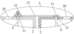
FIG. 2 is an enlarged view of portion A of FIG. 1;
FIG. 3 is an enlarged view of portion B of FIG. 1;
fig. 4 is a schematic side view of the transverse plate and the soil-shifting rod.
In the figure: 1. a base plate; 2. a seeding box; 3. a fertilizer box; 4. a first discharge pipe; 5. a second discharge pipe; 6. a first rotating shaft; 7. a first helical impeller; 8. a second rotating shaft; 9. a second helical impeller; 10. a stirring rod; 11. a first mounting hole; 12. a second mounting hole; 13. a belt pulley; 14. a belt; 15. a motor; 16. a storage battery; 17. a first hydraulic cylinder; 18. a first telescopic rod; 19. a plowshare; 20. a second hydraulic cylinder; 21. a second telescopic rod; 22. a connecting rod; 23. a chute; 24. a slide bar; 25. a spring; 26. a transverse plate; 27. a soil shifting rod; 28. a first feed inlet; 29. a second feed inlet; 30. a support pillar; 31. and a roller.
Detailed Description
The technical solutions in the embodiments of the present invention will be described clearly and completely with reference to the accompanying drawings in the embodiments of the present invention, and it is obvious that the described embodiments are only some embodiments of the present invention, not all embodiments. Based on the embodiments in the present invention, all other embodiments obtained by a person skilled in the art without creative work belong to the protection scope of the present invention.
As shown in fig. 1-4, the utility model provides a technical solution: an agricultural fertilizing and seeding device comprises a bottom plate 1, wherein a seeding box 2 and a fertilizer box 3 are fixedly mounted at the top of the bottom plate 1, a first discharging pipe 4 is fixedly mounted at the bottom of the seeding box 2, the first discharging pipe 4 is communicated with the inside of the seeding box 2, a second discharging pipe 5 is fixedly mounted at the bottom of the fertilizer box 3, the second discharging pipe 5 is communicated with the inside of the fertilizer box 3, the first discharging pipe 4 and the second discharging pipe 5 both penetrate through the bottom plate 1, a first rotating shaft 6 is arranged in the seeding box 2, a first helical impeller 7 is fixedly sleeved on the first rotating shaft 6, the bottom end of the first rotating shaft 6 and the bottom end of the first helical impeller 7 both extend into the first discharging pipe 4, a second rotating shaft 8 is arranged in the fertilizer box 3, six stirring rods 10 are fixedly mounted on both sides of the second rotating shaft 8, a second helical impeller 9 positioned below the stirring rods 10 is fixedly sleeved on the second rotating shaft 8, the bottom end of the second rotating shaft 8 and the bottom end of the second helical impeller 9, the seeding box 2 is provided with a first mounting hole 11 on the inner wall of the top, the top end of the first rotating shaft 6 penetrates through the first mounting hole 11, the fertilizer box 3 is provided with a second mounting hole 12 on the inner wall of the top, the top end of the second rotating shaft 8 penetrates through the second mounting hole 12, the top end of the first rotating shaft 6 and the top end of the second rotating shaft 8 are both fixedly sleeved with belt pulleys 13, two belt pulleys 13 are wound with the same belt 14, the top of the seeding box 2 is fixedly provided with a motor 15, the output shaft end of the motor 15 is fixedly connected with the top end of the first rotating shaft 6, the top of the bottom plate 1 is fixedly provided with a storage battery 16 and a first hydraulic cylinder 17, the output end of the first hydraulic cylinder 17 is fixedly provided with a first telescopic rod 18, the bottom end of the first telescopic rod 18 is fixedly provided with a plough 19, the top of the bottom plate 1 is fixedly provided with a second, the bottom fixed mounting of second telescopic link 21 has connecting rod 22, spout 23 has been seted up to connecting rod 22's bottom, sliding mounting has slide bar 24 in spout 23, slide bar 24's bottom extends to spout 23 outer and fixed mounting has diaphragm 26, the bottom fixed mounting of diaphragm 26 has soil shifting rod 27, slide bar 24's top fixed mounting has spring 25, spring 25's top and spout 23's top inner wall fixed connection, first charge door 28 has been seted up on the top inner wall of seeding case 2, second charge door 29 has been seted up on the top inner wall of fertilizer case 3.
Four supporting columns 30 are fixedly installed at the bottom of the bottom plate 1, the four supporting columns 30 are arranged in pairwise symmetry, rollers 31 are installed at the bottom ends of the four supporting columns 30 in a rotating mode, a vertical plate is fixedly installed at the top of the bottom plate 1, a grab bar is fixedly installed at one side, away from the second hydraulic cylinder 20, of the vertical plate, gate valves are fixedly installed at the bottoms of the first discharging pipe 4 and the second discharging pipe 5, bearings are fixedly sleeved on the first rotating shaft 6 and the second rotating shaft 8, outer rings of the two bearings are fixedly connected with the inner walls of the first mounting hole 11 and the second mounting hole 12 respectively, a first through hole and a second through hole are formed in the top of the bottom plate 1, the bottom end of the first telescopic rod 18 penetrates through the first through hole, the bottom end of the second telescopic rod 21 penetrates through the second through hole, the soil poking rods 27 are multiple, the soil poking rods 27 are arranged at equal intervals, limiting grooves are formed in the, the two limiting blocks are respectively installed in the two limiting grooves in a sliding mode.
When in use, a control switch is fixedly installed on the bottom plate 1, a motor 15, a storage battery 16, a first hydraulic cylinder 17, a second hydraulic cylinder 20 and the control switch are sequentially and electrically connected to form a loop, the storage battery 16 can be used for supplying power to the motor 15, the first hydraulic cylinder 17 and the second hydraulic cylinder 20 can be used for controlling the start-stop work of the motor 15, the control switch can also be used for controlling the start-stop and reset work of the first hydraulic cylinder 17 and the second hydraulic cylinder 20, a proper amount of crop seeds can be added into the sowing box 2 through a first feed opening 28, a proper amount of granular fertilizer can be added into the fertilizer box 3 through a second feed opening 29, the equipment can be pushed to move by four rollers 31, the equipment is moved into the field, the first hydraulic cylinder 17 is started to work, after a first telescopic rod 18 pushes a plough head 19 to move downwards to a proper depth in soil, the first hydraulic cylinder 17 is stopped to, the second hydraulic cylinder 20 is started to work, the second telescopic rod 21 pushes the connecting rod 22, the sliding rod 24, the transverse plate 26 and the plurality of soil stirring rods 27 to move downwards, the second hydraulic cylinder 20 stops working after the soil stirring rods 27 move downwards to be contacted with the ground surface, the motor 15 is started to work again, the motor 15 drives the first rotating shaft 6, the belt pulley 13 on the first rotating shaft 6 and the first spiral impeller 7 to rotate at a low speed, the second rotating shaft 8, the second spiral impeller 9 and the twelve stirring rods 10 rotate under the transmission action of the belt 14, two gate valves are opened, so that crop seeds in the seeding box 2 can be conveyed into the first discharging pipe 4 at a uniform speed and discharged from the first discharging pipe 4 under the conveying action of the first spiral impeller 7, the granular fertilizer in the fertilizer box 3 can be conveyed into the discharging pipe 5 and discharged from the second discharging pipe 5 by the second spiral impeller 9, and the twelve stirring rods 10 are rotated, can mix and stir fertilizer evenly, hold the grab bar and promote the equipment to move ahead at the uniform velocity, utilize the ploughshare 19 to set up the microscler slot on the soil, the crops seed falls into the slot from first discharging pipe 4, granular fertilizer falls into the slot from second discharging pipe 5, then utilize a plurality of striking rods 27 can push the soil that the slot edge turned out to the slot, bury crops seed and fertilizer, under the elastic force of spring 25, when a plurality of striking rods 27 meet the ground irregularity, striking rods 27 can push slide bar 24 to slide in spout 23, slide bar 24 drives two stopper to slide in two spacing grooves, spring 25 receives compression deformation to produce elasticity, thus automatically adjust the height of a plurality of striking rods 27, be convenient for pushing soil into the slot, thus along with constantly pushing the equipment to move ahead, the work of opening the slot, sowing, fertilizing and burying earthing is carried on at the same time, the working efficiency is improved, the labor intensity is reduced, after the work is finished, the motor 15 is stopped to work, the two gate valves are closed, the first hydraulic cylinder 17 and the second hydraulic cylinder 20 are started to reset, the first telescopic rod 18 drives the plough head 19 to move upwards to the original position, the second telescopic rod 21 drives the connecting rod 22, the sliding rod 24, the transverse plate 26 and the soil shifting rods 27 to move upwards to the original position, and meanwhile, the content which is not described in detail in the specification belongs to the prior art which is known by the technical personnel in the field.
To sum up, the agricultural fertilizing and seeding device can add a proper amount of crop seeds into the seeding box 2 through the first feed opening 28, add a proper amount of granular fertilizer into the fertilizer box 3 through the second feed opening 29, utilize the four rollers 31 to push the device to move, start the first hydraulic cylinder 17 to work, stop the first hydraulic cylinder 17 to work after the first telescopic rod 18 pushes the plowshare 19 to move downwards to a proper depth in the soil, start the second hydraulic cylinder 20 to work, the second telescopic rod 21 pushes the connecting rod 22, the sliding rod 24, the transverse plate 26 and the plurality of soil stirring rods 27 to move downwards, so that the soil stirring rods 27 move downwards to be in contact with the ground, stop the second hydraulic cylinder 20 to work, start the motor 15 to work, the motor 15 drives the first rotating shaft 6, the belt pulley 13 on the first rotating shaft 6 and the first spiral impeller 7 to rotate at a low speed, under the transmission action of the belt 14, the second rotating shaft 8, the second spiral impeller 9 and the twelve stirring rods 10 are made to rotate, two gate valves are opened, crop seeds in the seeding box 2 are uniformly discharged from the first discharging pipe 4 by the rotation of the first spiral impeller 7, granular fertilizer in the fertilizer box 3 is uniformly discharged from the second discharging pipe 5 by the rotation of the second spiral impeller 9, the fertilizer can be uniformly mixed and stirred by the rotation of the twelve stirring rods 10, the equipment is pushed to move forwards at a uniform speed by holding a grab bar, a long groove is formed in the land by using the plough head 19, the crop seeds fall into the groove from the first discharging pipe 4, the granular fertilizer falls into the groove from the second discharging pipe 5, soil turned out from the edge of the groove can be pushed into the groove by using a plurality of soil stirring rods 27 to cover the crop seeds and the fertilizer, when the plurality of soil stirring rods 27 meet the uneven ground, the soil stirring rods 27 can push the sliding rods 24 to slide in the sliding grooves 23, spring 25 receives compression deformation to produce elasticity to highly carrying out automatically regulated to a plurality of stirring pole 27, being convenient for push away soil to the ditch inslot, thereby burying work going on simultaneously to ditching slot, seeding, fertilization and earthing, work efficiency improves, the utility model relates to a rationally, the practicality is good, and easy operation is sowing the fertilization in-process, can go on simultaneously to ditching slot, seeding, fertilization and earthing burying work in the soil, has improved work efficiency, has reduced intensity of labour.
Claims (7)
1. The utility model provides an agricultural fertilizing and seeding device, includes bottom plate (1), its characterized in that: the top fixed mounting of bottom plate (1) has seeding case (2) and fertilizer case (3), the bottom fixed mounting of seeding case (2) has first discharging pipe (4), first discharging pipe (4) and seeding case (2) inside are linked together, the bottom fixed mounting of fertilizer case (3) has second discharging pipe (5), second discharging pipe (5) and fertilizer case (3) inside are linked together, bottom plate (1) is all run through in first discharging pipe (4) and second discharging pipe (5), be equipped with first pivot (6) in seeding case (2), fixed cover is equipped with first helical blade wheel (7) on first pivot (6), the bottom of first pivot (6) and the bottom of first helical blade wheel (7) all extend to in first discharging pipe (4), be equipped with second pivot (8) in fertilizer case (3), six puddlers (10) are all fixed mounting in the both sides of second pivot (8), a second spiral impeller (9) positioned below the stirring rod (10) is fixedly sleeved on the second rotating shaft (8), the bottom end of the second rotating shaft (8) and the bottom end of the second spiral impeller (9) both extend into the second discharging pipe (5), a first mounting hole (11) is formed in the inner wall of the top of the sowing box (2), the top end of the first rotating shaft (6) penetrates through the first mounting hole (11), a second mounting hole (12) is formed in the inner wall of the top of the fertilizer box (3), the top end of the second rotating shaft (8) penetrates through the second mounting hole (12), belt pulleys (13) are fixedly sleeved on the top end of the first rotating shaft (6) and the top end of the second rotating shaft (8), the same belt (14) is wound on the two belt pulleys (13), a motor (15) is fixedly installed at the top of the sowing box (2), the output shaft end of the motor (15) is fixedly connected with the top end of the first rotating shaft (6), the top of the bottom plate (1) is fixedly provided with a storage battery (16) and a first hydraulic cylinder (17), the output end of the first hydraulic cylinder (17) is fixedly provided with a first telescopic rod (18), the bottom end of the first telescopic rod (18) is fixedly provided with a plowshare (19), the top of the bottom plate (1) is fixedly provided with a second hydraulic cylinder (20), the output end of the second hydraulic cylinder (20) is fixedly provided with a second telescopic rod (21), the bottom end of the second telescopic rod (21) is fixedly provided with a connecting rod (22), the bottom end of the connecting rod (22) is provided with a sliding chute (23), a sliding rod (24) is arranged in the sliding chute (23), the bottom end of the sliding rod (24) extends out of the sliding chute (23) and is fixedly provided with a transverse plate (26), the bottom of the transverse plate (26) is fixedly provided with a soil poking rod (27), the top end of the sliding rod (24) is, a first feed opening (28) is formed in the inner wall of the top of the sowing box (2), and a second feed opening (29) is formed in the inner wall of the top of the fertilizer box (3).
2. The agricultural fertilizing and seeding device as claimed in claim 1, wherein: the bottom fixed mounting of bottom plate (1) has four support columns (30), and four support columns (30) are two bisymmetry settings, and gyro wheel (31) are all installed in the bottom of four support columns (30) rotation.
3. The agricultural fertilizing and seeding device as claimed in claim 1, wherein: the top fixed mounting of bottom plate (1) has the riser, and one side fixed mounting that second pneumatic cylinder (20) was kept away from to the riser has the handrail pole, and the equal fixed mounting in bottom of first discharging pipe (4) and second discharging pipe (5) has the gate valve.
4. The agricultural fertilizing and seeding device as claimed in claim 1, wherein: the bearing is fixedly sleeved on the first rotating shaft (6) and the second rotating shaft (8), and the outer rings of the two bearings are fixedly connected with the inner walls of the first mounting hole (11) and the second mounting hole (12) respectively.
5. The agricultural fertilizing and seeding device as claimed in claim 1, wherein: the top of the bottom plate (1) is provided with a first through hole and a second through hole, the bottom end of the first telescopic rod (18) penetrates through the first through hole, and the bottom end of the second telescopic rod (21) penetrates through the second through hole.
6. The agricultural fertilizing and seeding device as claimed in claim 1, wherein: the quantity of stirring native pole (27) is a plurality of, and a plurality of stirring native poles (27) are equidistant arranging.
7. The agricultural fertilizing and seeding device as claimed in claim 1, wherein: limiting grooves are formed in the inner walls of the two sides of the sliding groove (23), limiting blocks are fixedly mounted on the two sides of the sliding rod (24), and the two limiting blocks are slidably mounted in the two limiting grooves respectively.
Priority Applications (1)
| Application Number | Priority Date | Filing Date | Title |
|---|---|---|---|
| CN201922416804.0U CN211557960U (en) | 2019-12-29 | 2019-12-29 | Agricultural fertilizing and seeding device |
Applications Claiming Priority (1)
| Application Number | Priority Date | Filing Date | Title |
|---|---|---|---|
| CN201922416804.0U CN211557960U (en) | 2019-12-29 | 2019-12-29 | Agricultural fertilizing and seeding device |
Publications (1)
| Publication Number | Publication Date |
|---|---|
| CN211557960U true CN211557960U (en) | 2020-09-25 |
Family
ID=72551962
Family Applications (1)
| Application Number | Title | Priority Date | Filing Date |
|---|---|---|---|
| CN201922416804.0U Active CN211557960U (en) | 2019-12-29 | 2019-12-29 | Agricultural fertilizing and seeding device |
Country Status (1)
| Country | Link |
|---|---|
| CN (1) | CN211557960U (en) |
Cited By (5)
| Publication number | Priority date | Publication date | Assignee | Title |
|---|---|---|---|---|
| CN112205143A (en) * | 2020-11-06 | 2021-01-12 | 李合荣 | Agricultural equipment for improving soil in agriculture |
| CN112314087A (en) * | 2020-11-11 | 2021-02-05 | 黑龙江八一农垦大学 | Dig ground seeding integration machinery |
| CN114051780A (en) * | 2021-11-26 | 2022-02-18 | 苏州御湖园农业科技有限公司 | Cultivated land soil turning device for improving blueberry cultivation survival rate and soil turning backfilling method thereof |
| CN114303767A (en) * | 2021-12-02 | 2022-04-12 | 安徽省金寨县金龙玉珠茶业有限公司 | Method for planting green tea out of season |
| CN114902842A (en) * | 2022-04-06 | 2022-08-16 | 黑龙江农业经济职业学院 | Novel seeding device is used to agricultural |
-
2019
- 2019-12-29 CN CN201922416804.0U patent/CN211557960U/en active Active
Cited By (6)
| Publication number | Priority date | Publication date | Assignee | Title |
|---|---|---|---|---|
| CN112205143A (en) * | 2020-11-06 | 2021-01-12 | 李合荣 | Agricultural equipment for improving soil in agriculture |
| CN112314087A (en) * | 2020-11-11 | 2021-02-05 | 黑龙江八一农垦大学 | Dig ground seeding integration machinery |
| CN114051780A (en) * | 2021-11-26 | 2022-02-18 | 苏州御湖园农业科技有限公司 | Cultivated land soil turning device for improving blueberry cultivation survival rate and soil turning backfilling method thereof |
| CN114303767A (en) * | 2021-12-02 | 2022-04-12 | 安徽省金寨县金龙玉珠茶业有限公司 | Method for planting green tea out of season |
| CN114902842A (en) * | 2022-04-06 | 2022-08-16 | 黑龙江农业经济职业学院 | Novel seeding device is used to agricultural |
| CN114902842B (en) * | 2022-04-06 | 2023-01-31 | 黑龙江农业经济职业学院 | Novel seeding device is used to agricultural |
Similar Documents
| Publication | Publication Date | Title |
|---|---|---|
| CN211557960U (en) | Agricultural fertilizing and seeding device | |
| CN201690747U (en) | Automatic fertilizing device hung on rotary cultivator | |
| CN210298502U (en) | Seed fertilizer device for agricultural machinery | |
| CN109429596A (en) | A kind of agricultural fertilizer device | |
| CN103299745A (en) | Method for integrating punching and fertilization of border trees | |
| CN212393232U (en) | Organic fertilizer water, fertilizer and gas integrated fertilizer applicator for orchard | |
| CN209731995U (en) | Centrifugal adjustable precision sowing device | |
| CN219660333U (en) | Cabbage plants fertilizer injection unit | |
| CN103650724A (en) | Fertilizer distributor for returning paddy-field straws to field | |
| CN202759786U (en) | Paddy-field straw returning fertilizing machine | |
| CN214852798U (en) | Leisure agriculture picks garden facility fertilizer injection unit that grows seedlings | |
| CN209527155U (en) | A kind of adjustable fertilizer applicator of fertilization depth | |
| CN112868491B (en) | Engineering processing apparatus suitable for municipal garden and flowers management and maintenance | |
| CN213343265U (en) | Farming is with fertilization integrated device that digs | |
| Cui et al. | Development of 2ZFS-1A multifunctional tobacco transplanting machine | |
| CN109121495A (en) | A kind of agricultural fertilizer applicator of ploughing | |
| CN210928602U (en) | Fruit tree cultivation fertilizer injection equipment | |
| CN210746026U (en) | Farming fertilizer injection unit | |
| CN208480260U (en) | Sponge gourd cultivates equipment | |
| CN219761849U (en) | Soil turning and fertilizing device | |
| CN201450764U (en) | Nutrient medium covering machine for planting tobacco | |
| CN210406168U (en) | Shallow ditching dry land direct seeding machine for rice | |
| CN216567051U (en) | Hole fertilizing seeder with stable and efficient fertilizer distributor | |
| CN220570964U (en) | Water and fertilizer integrated seeder for seed production of corn | |
| CN216600786U (en) | Afforestation nursery stock fertilizer preparation facilities of reinforcing slow-release effect |
Legal Events
| Date | Code | Title | Description |
|---|---|---|---|
| GR01 | Patent grant | ||
| GR01 | Patent grant |