CN211556503U - Intelligent control device of switch cabinet - Google Patents
Intelligent control device of switch cabinet Download PDFInfo
- Publication number
- CN211556503U CN211556503U CN202020272162.1U CN202020272162U CN211556503U CN 211556503 U CN211556503 U CN 211556503U CN 202020272162 U CN202020272162 U CN 202020272162U CN 211556503 U CN211556503 U CN 211556503U
- Authority
- CN
- China
- Prior art keywords
- control device
- intelligent control
- device body
- switch
- switch cabinet
- Prior art date
- Legal status (The legal status is an assumption and is not a legal conclusion. Google has not performed a legal analysis and makes no representation as to the accuracy of the status listed.)
- Active
Links
- 230000005540 biological transmission Effects 0.000 claims abstract description 3
- 238000001514 detection method Methods 0.000 claims description 13
- 229920001971 elastomer Polymers 0.000 claims description 7
- 239000012212 insulator Substances 0.000 claims description 7
- 244000043261 Hevea brasiliensis Species 0.000 claims description 3
- 230000017525 heat dissipation Effects 0.000 claims description 3
- 238000003780 insertion Methods 0.000 claims description 3
- 230000037431 insertion Effects 0.000 claims description 3
- 239000000463 material Substances 0.000 claims description 3
- 229920003052 natural elastomer Polymers 0.000 claims description 3
- 229920001194 natural rubber Polymers 0.000 claims description 3
- 210000000056 organ Anatomy 0.000 description 6
- 238000012986 modification Methods 0.000 description 2
- 230000004048 modification Effects 0.000 description 2
- 238000010276 construction Methods 0.000 description 1
- 230000008595 infiltration Effects 0.000 description 1
- 238000001764 infiltration Methods 0.000 description 1
- 238000009434 installation Methods 0.000 description 1
- 238000012544 monitoring process Methods 0.000 description 1
- 230000003245 working effect Effects 0.000 description 1
Images

Landscapes
- Patch Boards (AREA)
Abstract
The utility model discloses an intelligent control device of a switch cabinet, which comprises an intelligent control device body, wherein the outer side of the intelligent control device body is provided with a buckle groove all around, the outer side of the intelligent control device body is provided with an indicator plate, one side of the indicator plate is provided with an indicator lamp, one side of the indicator lamp is provided with a display screen, the bottom of the display screen is provided with a humidity control module switch, the bottom of the humidity control module switch is rotatably connected with a temperature switch, the other side of the indicator plate is rotatably connected with a switching-on/off switch, the top of the switching-on/off switch is fixedly connected with a high-voltage electrified control box, the top of the high-voltage electrified control box is provided with a voice prompter, the bottom of the intelligent control device body is in transmission connection with a sliding cover, the inner side of the sliding cover is fixedly connected with a lug, and the two sides of the intelligent control device body, the accuracy of the device operation is ensured.
Description
Technical Field
The utility model relates to a cubical switchboard technical field specifically is a cubical switchboard intelligence control device.
Background
At present, along with the rapid development of economy, people also increase increasingly to the demand of the energy, the power plant, the construction of distribution facilities such as transformer substation, make switchgear's intellectuality become an indispensable demand, however general cubical switchboard, not only the structure is complicated, and can not in time effectually show the running state, very big increase the operation degree of difficulty, the staff does not have high identifiability in the operation simultaneously, very cause the trouble easily, and can't avoid non-professional's improper operation, when the cubical switchboard is at work, the temperature has greatly influenced its working property with humidity, the person can cause the incident even, most cubical switchboard operating means control button etc. all directly expose in the outside simultaneously, cause the rainwater to get into very easily, cause the danger of electric leakage. Therefore, the intelligent control device for the switch cabinet is improved.
SUMMERY OF THE UTILITY MODEL
In order to solve the technical problem, the utility model provides a following technical scheme:
the utility model relates to an intelligent control device of a switch cabinet, which comprises an intelligent control device body, wherein the outer side of the intelligent control device body is provided with a catching groove all around, an indicating plate is arranged on the outer side of the intelligent control device body, an indicating lamp is arranged on one side of the indicating plate, a display screen is arranged on one side of the indicator light, a humidity control module switch is arranged at the bottom of the display screen, the bottom of the humidity control module switch is rotationally connected with a temperature switch, the other side of the indicating plate is rotationally connected with a switch-on/off switch, the top of the switch-on/off switch is fixedly connected with a high-voltage electrified control box, the top of the high-voltage electrified control box is provided with a voice prompter, the bottom of the intelligent control device body is connected with a sliding cover in a transmission way, both ends of the top of the sliding cover are rotationally connected with nail buttons, the inner side of the sliding cover is fixedly connected with a convex block, and grooves are formed in two ends of the intelligent control device body.
As a preferred technical scheme of the utility model, one side of intelligence controlling device body is equipped with louvre and plug wire hole, plug wire hole fixed connection is in the bottom of louvre.
As a preferred technical scheme of the utility model, the both sides of intelligence controlling device body are equipped with the recess, sliding connection between recess and the lug.
As a preferred technical scheme of the utility model, the inside of intelligence controlling device body is equipped with temperature detect module and temperature alarm module, temperature detect module passes through connecting wire and temperature switch electric connection.
As a preferred technical scheme of the utility model, the inside of intelligence controlling device body is equipped with humidity control module, humidity control module passes through connecting wire and pilot lamp and humidity control module switch electric connection.
As an optimal technical scheme of the utility model, the inside of intelligence controlling device body is equipped with bee calling organ, bee calling organ passes through connecting wire and voice prompt electric connection.
As an optimal technical scheme of the utility model, the inboard of intelligence controlling device body is fixed with the insulator, the insulator is made through the natural rubber material.
As an optimal technical scheme of the utility model, intelligence controlling device body top and bottom all are equipped with the rubber strip along the horizontal direction, bottom rubber strip and sliding closure fixed connection.
The utility model has the advantages that: the inside of intelligent control device body is equipped with temperature detection module and temperature alarm module, temperature detection module passes through connecting wire and temperature switch electric connection, can effectively monitor the inside temperature condition, prevent that inside high temperature from causing the damage, the inside of intelligent control device body still is equipped with humidity control module, humidity control module passes through connecting wire and pilot lamp and humidity control module switch electric connection, can effectively monitor the inside humidity condition through the humidity control module that is equipped with, simultaneously through the setting of sliding closure, inside rainwater has been prevented to enter into cubical switchboard intelligent control device, ensure the accuracy of device work.
Drawings
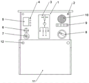
Fig. 1 is a structural front view of the intelligent control device for the switch cabinet of the present invention;
fig. 2 is a structural side view of the intelligent control device for the switch cabinet of the present invention;
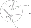
fig. 3 is a schematic view of a catching groove structure of the intelligent control device for the switch cabinet of the present invention;
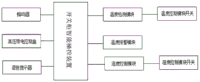
fig. 4 is the utility model relates to a cubical switchboard intelligence controlling means's program diagram.
In the figure: 1. an intelligent control device body; 2. buckling grooves; 3. an indicator panel; 4. an indicator light; 5. a display screen; 6. a humidity control module switch; 7. a temperature switch; 8. a switch-on/off switch; 9. a high-voltage live control box; 10. a voice prompter; 11. a sliding cover; 12. buckling; 13. heat dissipation holes; 14. a wire insertion hole; 15. a groove; 16. and (4) a bump.
Detailed Description
The preferred embodiments of the present invention will be described in conjunction with the accompanying drawings, and it will be understood that they are presented herein only to illustrate and explain the present invention, and not to limit the present invention.
Example (b): as shown in FIGS. 1-4, the utility model relates to an intelligent control device of a switch cabinet, which comprises an intelligent control device body 1, a fastening groove 2 is arranged around the outer side of the intelligent control device body 1, an indicator plate 3 is arranged on the outer side of the intelligent control device body 1, an indicator lamp 4 is arranged on one side of the indicator plate 3, a display screen 5 is arranged on one side of the indicator lamp 4, a humidity control module switch 6 is arranged on the bottom of the display screen 5, a temperature switch 7 is rotatably connected on the bottom of the humidity control module switch 6, an opening and closing switch 8 is rotatably connected on the other side of the indicator plate 3, a high-voltage electrified control box 9 is fixedly connected on the top of the opening and closing switch 8, a voice prompter 10 is arranged on the top of the high-voltage electrified control box 9, a sliding cover 11 is rotatably connected on the bottom of the intelligent control device body 1, buttons 12 are rotatably connected, two ends of the intelligent control device body 1 are provided with grooves 15.
Wherein, one side of intelligence control device body 1 is equipped with louvre 13 and plug wire hole 14, and plug wire hole 14 fixed connection is in louvre 13's bottom, and one side of intelligence control device body is equipped with the inside thermal fast dissipation of being convenient for of louvre.
The two sides of the intelligent control device body 1 are provided with the protruding blocks 16, the groove 15 is in sliding connection with the protruding blocks 16, the sliding connection between the groove 15 and the protruding blocks 16 facilitates operation of an operator on the sliding cover, and meanwhile, due to the arrangement of the sliding cover, rainwater is prevented from entering the intelligent control device of the switch cabinet.
Wherein, the inside of intelligent control device body 1 is equipped with temperature detection module and temperature alarm module, and temperature detection module passes through connecting wire and temperature switch 7 electric connection, and the inside through the intelligent control device body is equipped with temperature detection module and temperature alarm module and can effectively monitor the inside temperature condition, prevents that inside high temperature from causing the damage.
Wherein, the inside of intelligent control device body 1 is equipped with humidity control module, and humidity control module passes through connecting wire and pilot lamp 4 and humidity control module switch 6 electric connection, and the inside through the intelligent control device body is equipped with the inside humidity condition that humidity control module can effectively monitor.
Wherein, the inside of intelligent control device body 1 is equipped with bee calling organ, and bee calling organ passes through connecting wire and 10 electric connection of voice prompt, through installation control bee calling organ, when the inside temperature and humidity of supervisory control cubical switchboard takes place unusually, through the bee calling organ that is equipped with, takes place the sound fast, reminds operating personnel.
Wherein, the inboard of intelligent control device body 1 is fixed with the insulator, and the insulator passes through the natural rubber material to be made, in case because of reasons such as sleet weather make intelligent control box take place the electric leakage phenomenon, accessible insulator prevents to communicate with outside conducting medium, protection outside personnel work safety.
Wherein, 1 top of intelligent control device body and bottom all are equipped with the rubber strip along the horizontal direction, and bottom rubber strip and sliding closure 11 fixed connection all are equipped with the rubber strip along the horizontal direction at intelligent control device body top and bottom and prevent rainwater from top and bottom infiltration.
The working principle is as follows: firstly, checking whether the device is normal, when the device is used, installing a sliding cover 1 in a mounting groove on a switch cabinet, arranging convex blocks 16 at two ends of the sliding cover 1, arranging grooves 16 at two sides of an intelligent control device body 1, and connecting the grooves 15 and the convex blocks 16 in a sliding way, wherein the sliding connection between the grooves 15 and the convex blocks 16 is convenient for an operator to operate the sliding cover, simultaneously preventing rainwater from entering the intelligent control device of the switch cabinet through the arrangement of the sliding cover 11, wiring according to requirements, electrifying to start working, observing the internal conditions through an indicating plate 3, an indicating lamp 4 and a display screen 5, arranging a temperature detection module and a temperature alarm module in the intelligent control device body 1, electrically connecting the temperature detection module with a temperature switch 7 through a connecting wire, and effectively monitoring the internal temperature conditions through arranging the temperature detection module and the temperature alarm module in the intelligent control device body 1, prevent that inside high temperature from causing the loss, the inside of intelligent control device body 1 still is equipped with humidity control module, humidity control module passes through connecting wire and pilot lamp 4 and humidity control module switch 6 electric connection, it can effectively monitor the inside humidity condition to be equipped with humidity control module through the inside of intelligent control device body 1, the inside of intelligent control device body 1 is equipped with temperature detection module and temperature alarm module simultaneously, temperature detection module passes through connecting wire and 7 electric connection of temperature switch, it can effectively monitor the inside temperature condition to be equipped with temperature detection module and temperature alarm module through the inside of intelligent control device body 1, prevent that inside high temperature from causing the damage.
Although the present invention has been described in detail with reference to the foregoing embodiments, it will be apparent to those skilled in the art that modifications may be made to the embodiments described in the foregoing embodiments, or equivalents may be substituted for elements thereof. Any modification, equivalent replacement, or improvement made within the spirit and principle of the present invention should be included in the protection scope of the present invention.
Claims (8)
1. An intelligent control device of a switch cabinet comprises an intelligent control device body (1) and is characterized in that a catching groove (2) is formed in the periphery of the outer side of the intelligent control device body (1), an indicating plate (3) is arranged on the outer side of the intelligent control device body (1), an indicating lamp (4) is arranged on one side of the indicating plate (3), a display screen (5) is arranged on one side of the indicating lamp (4), a humidity control module switch (6) is arranged at the bottom of the display screen (5), a temperature switch (7) is rotatably connected to the bottom of the humidity control module switch (6), a switch-on/off switch (8) is rotatably connected to the other side of the indicating plate (3), a high-voltage electrified control box (9) is fixedly connected to the top of the switch-on/off switch (8), and a voice prompter (10) is arranged on the top of the high-voltage electrified control box (9, the intelligent control device comprises an intelligent control device body (1) and is characterized in that a sliding cover (11) is connected to the bottom of the intelligent control device body (1) in a transmission mode, nail buttons (12) are connected to two ends of the top of the sliding cover (11) in a rotating mode, protruding blocks (16) are fixedly connected to the inner side of the sliding cover (11), and grooves (15) are arranged at two ends of the intelligent control device body (1).
2. The intelligent control device for the switch cabinet according to claim 1, wherein one side of the intelligent control device body (1) is provided with a heat dissipation hole (13) and a wire insertion hole (14), and the wire insertion hole (14) is fixedly connected to the bottom of the heat dissipation hole (13).
3. The intelligent control device for the switch cabinet according to claim 1, wherein the intelligent control device body (1) is provided with a protrusion (16) at two sides, and the groove (15) is slidably connected with the protrusion (16).
4. The intelligent control device for the switch cabinet according to claim 1, wherein a temperature detection module and a temperature alarm module are arranged inside the intelligent control device body (1), and the temperature detection module is electrically connected with the temperature switch (7) through a connecting wire.
5. The intelligent control device for the switch cabinet according to claim 1, wherein a humidity control module is arranged inside the intelligent control device body (1), and the humidity control module is electrically connected with the indicator lamp (4) and the humidity control module switch (6) through a connecting wire.
6. The intelligent control device for the switch cabinet according to claim 1, wherein a buzzer is arranged inside the intelligent control device body (1), and the buzzer is electrically connected with the voice prompt (10) through a connecting wire.
7. The intelligent operating device for the switch cabinet according to claim 1, wherein an insulator is fixed on the inner side of the intelligent operating device body (1), and the insulator is made of a natural rubber material.
8. The intelligent control device for the switch cabinet according to claim 1, wherein rubber strips are arranged on the top and the bottom of the intelligent control device body (1) along the horizontal direction, and the bottom rubber strip is fixedly connected with the sliding cover (11).
Priority Applications (1)
| Application Number | Priority Date | Filing Date | Title |
|---|---|---|---|
| CN202020272162.1U CN211556503U (en) | 2020-03-09 | 2020-03-09 | Intelligent control device of switch cabinet |
Applications Claiming Priority (1)
| Application Number | Priority Date | Filing Date | Title |
|---|---|---|---|
| CN202020272162.1U CN211556503U (en) | 2020-03-09 | 2020-03-09 | Intelligent control device of switch cabinet |
Publications (1)
| Publication Number | Publication Date |
|---|---|
| CN211556503U true CN211556503U (en) | 2020-09-22 |
Family
ID=72494785
Family Applications (1)
| Application Number | Title | Priority Date | Filing Date |
|---|---|---|---|
| CN202020272162.1U Active CN211556503U (en) | 2020-03-09 | 2020-03-09 | Intelligent control device of switch cabinet |
Country Status (1)
| Country | Link |
|---|---|
| CN (1) | CN211556503U (en) |
Cited By (1)
| Publication number | Priority date | Publication date | Assignee | Title |
|---|---|---|---|---|
| CN112327040A (en) * | 2020-11-17 | 2021-02-05 | 国网安徽省电力有限公司电力科学研究院 | High voltage live display detector |
-
2020
- 2020-03-09 CN CN202020272162.1U patent/CN211556503U/en active Active
Cited By (1)
| Publication number | Priority date | Publication date | Assignee | Title |
|---|---|---|---|---|
| CN112327040A (en) * | 2020-11-17 | 2021-02-05 | 国网安徽省电力有限公司电力科学研究院 | High voltage live display detector |
Similar Documents
| Publication | Publication Date | Title |
|---|---|---|
| CN206619006U (en) | Intermediate switchgear cabinet and switch cubicle monitoring system | |
| CN212258194U (en) | High-voltage distribution box with electric leakage detection function | |
| CN206546968U (en) | A kind of important electric elements detection distribution box in real time | |
| CN205583390U (en) | But real time monitoring's comprehensive switch board | |
| CN205863768U (en) | A kind of monitoring alarm device of power distribution station | |
| CN111682422A (en) | a secondary box | |
| CN217882458U (en) | Intelligent fusion ring net cage | |
| CN205984704U (en) | Dual -power automatic transfer switch | |
| CN206225261U (en) | A kind of disconnecting switch protective enclosure | |
| CN208723535U (en) | A kind of water inlet auto-power-off device of backstage observing and controlling cabinet | |
| CN205248685U (en) | An all-weather underground box-type switch station | |
| CN212991671U (en) | a secondary box | |
| CN218334842U (en) | Outdoor looped netowrk cabinet with ventilation dehumidification function | |
| CN210669005U (en) | A power switch cabinet with alarm function | |
| CN216055819U (en) | Safety early warning equipment of high-low voltage transformer cabinet | |
| CN221305354U (en) | Ventilation device of distribution room | |
| CN214625865U (en) | Take looped netowrk cabinet of intelligent fault reporting device | |
| CN206712437U (en) | A kind of cable branch box | |
| CN112103792A (en) | High-voltage circuit breaker for power distribution system | |
| CN205846459U (en) | Solar switch cabinet | |
| CN205846458U (en) | High-voltage switch cabinet with high safety | |
| CN206818750U (en) | A kind of DC system insulating monitoring instrument electrification replacing tool | |
| CN110676706A (en) | Power distribution cabinets, power distribution devices and inspection systems | |
| CN221783669U (en) | A high voltage switch cabinet with protection function | |
| CN210167704U (en) | Outdoor case of european style environment-friendly becomes box |
Legal Events
| Date | Code | Title | Description |
|---|---|---|---|
| GR01 | Patent grant | ||
| GR01 | Patent grant |