CN211550753U - A quick-installed three-way anti-seismic support hanger - Google Patents
A quick-installed three-way anti-seismic support hanger Download PDFInfo
- Publication number
- CN211550753U CN211550753U CN201922267507.4U CN201922267507U CN211550753U CN 211550753 U CN211550753 U CN 211550753U CN 201922267507 U CN201922267507 U CN 201922267507U CN 211550753 U CN211550753 U CN 211550753U
- Authority
- CN
- China
- Prior art keywords
- rod
- straight
- fixedly connected
- straight rod
- quick
- Prior art date
- Legal status (The legal status is an assumption and is not a legal conclusion. Google has not performed a legal analysis and makes no representation as to the accuracy of the status listed.)
- Expired - Fee Related
Links
Images


Landscapes
- Supports For Pipes And Cables (AREA)
Abstract
本实用新型公开了一种快装式三向抗震支吊架,包括横梁,所述横梁的外表面开设有滑槽,所述滑槽的内部设有丝杆,所述丝杆的外表面套设有通过螺纹转动连接的平移板,所述平移板的下表面固定连接有支撑板,所述丝杆的一端贯穿横梁的一侧并延伸至外部,且所述丝杆位于横梁外侧的一端固定连接有旋钮。本实用新型中,转动第一直杆使得第一直杆和第二直杆之间的长度改变,可以对整个装置进行固定,提高装置的稳定性和抗震能力,可以适应多种不是水平的安装的位置,让装置使用范围变大,旋转旋钮,旋钮转动带动丝杆转动,丝杆转动带动平移板在滑槽内进行移动,从而改变管道的位置,对管道进行调节,来配合管道的连接。

The utility model discloses a quick-installed three-way anti-seismic support and hanger, comprising a cross beam, a chute is provided on the outer surface of the cross beam, a screw rod is arranged inside the chute, and the outer surface of the screw rod is sleeved There is a translation plate connected by threaded rotation, the lower surface of the translation plate is fixedly connected with a support plate, one end of the screw rod penetrates one side of the beam and extends to the outside, and the end of the screw rod located on the outside of the beam is fixed A knob is attached. In the utility model, rotating the first straight rod makes the length between the first straight rod and the second straight rod change, the whole device can be fixed, the stability and anti-vibration ability of the device can be improved, and various installations that are not horizontal can be adapted. Rotate the knob, the rotation of the knob drives the screw rod to rotate, and the rotation of the screw rod drives the translation plate to move in the chute, thereby changing the position of the pipeline and adjusting the pipeline to match the connection of the pipeline.
Description
技术领域technical field
本实用新型涉及建筑安装和固定技术领域,尤其涉及一种快装式三向抗震支吊架。The utility model relates to the technical field of building installation and fixing, in particular to a quick-installed three-way anti-seismic support and hanger.
背景技术Background technique
抗震支吊架是限制附属机电工程设施产生位移,控制设施振动,并将荷载传递至承载结构上的各类组件或装置。经抗震加固后的建筑给水排水、消防、供暖、通风、空调、燃气、热力、电力、通讯等机电工程设施,当遭遇到本地区抗震设防烈度的地震发生时,可以达到减轻地震破坏,减少和尽可能防止次生灾害的发生,从而达到减少人员伤亡及财产损失的目的;Seismic supports and hangers are various components or devices that limit the displacement of auxiliary mechanical and electrical engineering facilities, control the vibration of facilities, and transmit loads to the bearing structure. The mechanical and electrical engineering facilities such as water supply and drainage, fire protection, heating, ventilation, air conditioning, gas, heat, electricity, communication, etc. of the building after seismic reinforcement can reduce earthquake damage, reduce and To prevent the occurrence of secondary disasters as much as possible, so as to achieve the purpose of reducing casualties and property losses;
现有的三向抗震支吊架普遍结构复杂,安装效率低,且抗震性能不佳,且无法根据不同的设备安装需要进行位置调节,在某些管道安装时往往需要进行微调对齐,因此使用范围受到了限制,无法实现大范围的应用,且现有的抗震支吊架只通过单一的螺栓螺母的结构连接,稳定性不高,在地震时很难起到固定作用。The existing three-way seismic support and hanger are generally complex in structure, low in installation efficiency, and poor in seismic performance, and cannot be adjusted according to different equipment installation needs. Fine-tuning and alignment are often required when installing certain pipelines. Therefore, the scope of use It is limited and cannot be applied in a wide range, and the existing anti-seismic supports and hangers are only connected by a single bolt and nut structure, and the stability is not high, and it is difficult to play a fixed role in an earthquake.
实用新型内容Utility model content
本实用新型的目的是为了解决现有技术中存在的缺点,而提出的一种快装式三向抗震支吊架。The purpose of the utility model is to propose a quick-installed three-way anti-seismic support and hanger in order to solve the shortcomings existing in the prior art.
为了实现上述目的,本实用新型采用了如下技术方案:一种快装式三向抗震支吊架,包括横梁,所述横梁的外表面开设有滑槽,所述滑槽的内部设有丝杆,所述丝杆的外表面套设有通过螺纹转动连接的平移板,所述平移板的下表面固定连接有支撑板,所述丝杆的一端贯穿横梁的一侧并延伸至外部,且所述丝杆位于横梁外侧的一端固定连接有旋钮,所述横梁的上表面中心位置固定连接有支撑杆,所述支撑杆的外表面套设有套筒,所述支撑杆位于套筒内部的一端固定连接有挡板,所述套筒的顶端固定连接有第一安装板,所述横梁的上表面位于支撑杆两侧的位置固定连接有支座,所述支座的外表面转动连接有连接块,所述连接块的上表面固定连接有固定轴,所述横梁的上方位于支撑杆两侧的位置分别设有第一直杆,所述第一直杆的底部开设有通孔,所述固定轴的一端贯穿第一直杆的底部并延伸至通孔的内部,所述固定轴位于通孔内部的一端外表面套设有通过螺纹连接的第一螺母,所述第一直杆的另一端固定连接有螺纹杆,所述第一直杆的外表面套设有第二直杆,所述螺纹杆与第二直杆的内部通过螺纹转动连接,所述第一直杆位于第二直杆外部的一段外表面套设有通过螺纹转动连接的第二螺母,所述第二直杆的顶端转动连接有第二安装板。In order to achieve the above purpose, the utility model adopts the following technical scheme: a quick-installed three-way anti-seismic support and hanger, comprising a cross beam, the outer surface of the cross beam is provided with a chute, and the interior of the chute is provided with a screw rod , the outer surface of the screw rod is sleeved with a translation plate connected by threaded rotation, the lower surface of the translation plate is fixedly connected with a support plate, one end of the screw rod penetrates one side of the beam and extends to the outside, and all the A knob is fixedly connected to one end of the screw rod at the outer side of the beam, a support rod is fixedly connected to the center of the upper surface of the beam, a sleeve is sleeved on the outer surface of the support rod, and one end of the support rod is located inside the sleeve A baffle plate is fixedly connected, a first mounting plate is fixedly connected to the top of the sleeve, a support is fixedly connected to the upper surface of the beam on both sides of the support rod, and the outer surface of the support is rotatably connected with a connection The upper surface of the connecting block is fixedly connected with a fixed shaft, the upper part of the cross beam is located on both sides of the support rod with first straight rods, and the bottom of the first straight rod is provided with a through hole, the One end of the fixed shaft penetrates the bottom of the first straight rod and extends to the inside of the through hole, the outer surface of one end of the fixed shaft located inside the through hole is sleeved with a first nut connected by threads, and the other side of the first straight rod is sleeved. One end is fixedly connected with a threaded rod, the outer surface of the first straight rod is sleeved with a second straight rod, the threaded rod is connected with the inside of the second straight rod by threaded rotation, and the first straight rod is located in the second straight rod. A section of the outer surface of the outside of the rod is sleeved with a second nut that is rotatably connected by threads, and the top end of the second straight rod is rotatably connected with a second mounting plate.
作为上述技术方案的进一步描述:As a further description of the above technical solution:
所述支撑板的下表面固定连接有第一半环,所述第一半环的一端转动连接有第二半环,所述第一半环和第二半环的另一端通过螺栓固定连接。A first half ring is fixedly connected to the lower surface of the support plate, one end of the first half ring is rotatably connected with a second half ring, and the other ends of the first half ring and the second half ring are fixedly connected by bolts.
作为上述技术方案的进一步描述:As a further description of the above technical solution:
所述套筒的内部设有两个导向杆,两个所述导向杆均贯穿挡板,所述套筒的内部设有第一弹簧,所述第一弹簧的两端分别与挡板和套筒的内部固定连接。The inside of the sleeve is provided with two guide rods, both of which pass through the baffle plate, the inside of the sleeve is provided with a first spring, and the two ends of the first spring are respectively connected with the baffle plate and the sleeve. Internal fixed connection of the barrel.
作为上述技术方案的进一步描述:As a further description of the above technical solution:
所述第一安装板和第二安装板的外表面开设有多个螺栓孔,且多个所述螺栓孔对称开设外第一安装板和第二安装板的外表面。The outer surfaces of the first mounting plate and the second mounting plate are provided with a plurality of bolt holes, and the plurality of bolt holes are symmetrically opened on the outer surfaces of the outer first mounting plate and the second mounting plate.
作为上述技术方案的进一步描述:As a further description of the above technical solution:
所述第一直杆的底部与固定轴为转动连接。The bottom of the first straight rod is rotatably connected with the fixed shaft.
作为上述技术方案的进一步描述:As a further description of the above technical solution:
所述第二直杆的内部设有第二弹簧。A second spring is arranged inside the second straight rod.
本实用新型具有如下有益效果:The utility model has the following beneficial effects:
1、该快装式三向抗震支吊架,通过设置的第一安装板、第二安装板、第一弹簧、第二弹簧、第一直杆、螺纹杆、第二直杆和第二螺母,将第一安装板安装在固定位置,转动第一直杆,改变第一直杆漏出的长度,将第二安装板安装在合适的位置,转动第一直杆使得第一直杆和第二直杆之间拉紧,转动第二螺母,第二螺母将第一直杆锁紧,两边第一直杆和第二直杆可以对整个装置进行固定,提高装置的稳定性和抗震能力,通过第一直杆和第二直杆长度的改变可以适应多种不是水平的安装的位置,让装置使用范围变大,第一弹簧和第二弹簧可以增加装置的抗震性能。1. The quick-installed three-way anti-seismic support and hanger is equipped with the first mounting plate, the second mounting plate, the first spring, the second spring, the first straight rod, the threaded rod, the second straight rod and the second nut. , install the first mounting plate in a fixed position, turn the first straight rod, change the length of the first straight rod leaking out, install the second mounting plate in a proper position, turn the first straight rod so that the first straight rod and the second straight rod Tighten between the straight rods, turn the second nut, the second nut locks the first straight rod, the first straight rod and the second straight rod on both sides can fix the whole device, improve the stability and shock resistance of the device, through The change of the length of the first straight rod and the second straight rod can adapt to various installation positions that are not horizontal, so that the use range of the device is enlarged, and the first spring and the second spring can increase the shock resistance of the device.
2、该快装式三向抗震支吊架,通过设置的横梁、滑槽、丝杆、旋钮、平移板、支撑板、第一半环、第二半环和螺栓,通过第一半环、第二半环和螺栓,将管道固定在支撑板的下方,旋转旋钮,旋钮转动带动丝杆转动,丝杆转动带动平移板在滑槽内进行移动,从而改变管道的位置,对管道进行调节,来配合管道的连接。2. The quick-installed three-way anti-seismic support and hanger, through the set beam, chute, screw, knob, translation plate, support plate, first half ring, second half ring and bolts, through the first half ring, The second half ring and bolts fix the pipeline under the support plate, rotate the knob, the rotation of the knob drives the screw to rotate, and the rotation of the screw drives the translation plate to move in the chute, thereby changing the position of the pipeline and adjusting the pipeline. to match the pipe connection.
附图说明Description of drawings
图1为本实用新型的整体结构示意图;Fig. 1 is the overall structure schematic diagram of the present utility model;
图2为图1中A处的放大图;Fig. 2 is the enlarged view of A place in Fig. 1;
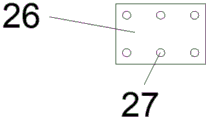
图3为本实用新型的第二安装板的结构示意图。FIG. 3 is a schematic structural diagram of the second mounting plate of the present invention.
图例说明:illustration:
1、横梁;2、滑槽;3、丝杆;4、平移板;5、支撑板;6、第一半环;7、第二半环;8、螺栓;9、旋钮;10、支撑杆;11、挡板;12、套筒;13、第一弹簧;14、导向杆;15、第一安装板;16、支座;17、连接块;18、固定轴;19、第一直杆;20、通孔;21、第一螺母;22、第二螺母;23、螺纹杆;24、第二弹簧;25、第二直杆;26、第二安装板;27、螺栓孔。1. Beam; 2. Chute; 3. Screw; 4. Translation plate; 5. Support plate; 6. First half-ring; 7. Second half-ring; 8. Bolt; 9. Knob; 10. Support rod ; 11, baffle plate; 12, sleeve; 13, first spring; 14, guide rod; 15, first mounting plate; 16, support; 17, connecting block; 18, fixed shaft; 19, first
具体实施方式Detailed ways
下面将结合本实用新型实施例中的附图,对本实用新型实施例中的技术方案进行清楚、完整地描述,显然,所描述的实施例仅仅是本实用新型一部分实施例,而不是全部的实施例。基于本实用新型中的实施例,本领域普通技术人员在没有做出创造性劳动前提下所获得的所有其他实施例,都属于本实用新型保护的范围。The technical solutions in the embodiments of the present utility model will be clearly and completely described below with reference to the accompanying drawings in the embodiments of the present utility model. Obviously, the described embodiments are only a part of the embodiments of the present utility model, rather than all the implementations. example. Based on the embodiments of the present invention, all other embodiments obtained by those of ordinary skill in the art without creative work fall within the protection scope of the present invention.
在本实用新型的描述中,需要说明的是,术语“中心”、“上”、“下”、“左”、“右”、“竖直”、“水平”、“内”、“外”等指示的方位或位置关系为基于附图所示的方位或位置关系,仅是为了便于描述本实用新型和简化描述,而不是指示或暗示所指的装置或元件必须具有特定的方位、以特定的方位构造和操作,因此不能理解为对本实用新型的限制;术语“第一”、“第二”、“第三”仅用于描述目的,而不能理解为指示或暗示相对重要性,此外,除非另有明确的规定和限定,术语“安装”、“相连”、“连接”应做广义理解,例如,可以是固定连接,也可以是可拆卸连接,或一体地连接;可以是机械连接,也可以是电连接;可以是直接相连,也可以通过中间媒介间接相连,可以是两个元件内部的连通。对于本领域的普通技术人员而言,可以具体情况理解上述术语在本实用新型中的具体含义。In the description of the present invention, it should be noted that the terms "center", "upper", "lower", "left", "right", "vertical", "horizontal", "inner" and "outer" The orientation or positional relationship indicated by etc. is based on the orientation or positional relationship shown in the accompanying drawings, which is only for the convenience of describing the present invention and simplifying the description, rather than indicating or implying that the referred device or element must have a specific orientation, with a specific orientation. Therefore, it should not be construed as a limitation to the present invention; the terms "first", "second" and "third" are only used for descriptive purposes, and should not be construed as indicating or implying relative importance. In addition, Unless otherwise expressly specified and limited, the terms "installed", "connected" and "connected" should be understood in a broad sense, for example, it may be a fixed connection, a detachable connection, or an integral connection; it may be a mechanical connection, It can also be an electrical connection; it can be a direct connection, an indirect connection through an intermediate medium, or an internal connection between two components. For those of ordinary skill in the art, the specific meanings of the above terms in the present invention can be understood in specific situations.
参照图1-3,本实用新型提供的一种实施例:一种快装式三向抗震支吊架,包括横梁1,横梁1的外表面开设有滑槽2,滑槽2的内部设有丝杆3,丝杆3的外表面套设有通过螺纹转动连接的平移板4,平移板4的下表面固定连接有支撑板5,丝杆3的一端贯穿横梁1的一侧并延伸至外部,且丝杆3位于横梁1外侧的一端固定连接有旋钮9,横梁1的上表面中心位置固定连接有支撑杆10,支撑杆10的外表面套设有套筒12,支撑杆10位于套筒12内部的一端固定连接有挡板11,套筒12的顶端固定连接有第一安装板15,横梁1的上表面位于支撑杆10两侧的位置固定连接有支座16,支座16的外表面转动连接有连接块17,连接块17的上表面固定连接有固定轴18,横梁1的上方位于支撑杆10两侧的位置分别设有第一直杆19,第一直杆19的底部开设有通孔20,固定轴18的一端贯穿第一直杆19的底部并延伸至通孔20的内部,固定轴18位于通孔20内部的一端外表面套设有通过螺纹连接的第一螺母21,第一直杆19的另一端固定连接有螺纹杆23,第一直杆19的外表面套设有第二直杆25,螺纹杆23与第二直杆25的内部通过螺纹转动连接,第一直杆19位于第二直杆25外部的一段外表面套设有通过螺纹转动连接的第二螺母22,第二直杆25的顶端转动连接有第二安装板26。1-3, an embodiment provided by the present utility model: a quick-installed three-way anti-seismic support and hanger, including a
支撑板5的下表面固定连接有第一半环6,第一半环6的一端转动连接有第二半环7,第一半环6和第二半环7的另一端通过螺栓8固定连接,第一半环6和第二半环7组成一个圆形,通过螺栓8可以将两个半环固定,从而将位于两个半环之间的管道进行固定,结构简单,便于操作;套筒12的内部设有两个导向杆14,两个导向杆14均贯穿挡板11,套筒12的内部设有第一弹簧13,第一弹簧13的两端分别与挡板11和套筒12的内部固定连接,导向杆14是为了让装置发生晃动时可以沿着导向杆14移动,避免左右晃动,第一弹簧13可以缓冲挡板11的冲击,从而起到更好的抗震作用;第一安装板15和第二安装板26的外表面开设有多个螺栓孔27,且多个螺栓孔27对称开设外第一安装板15和第二安装板26的外表面,多个螺栓孔27可以更加稳定的将装置进行固定,从而不会出现发生地震时装置被晃掉的结果;第一直杆19的底部与固定轴18为转动连接是为了可以通过转动第一直杆19来改变第一直杆19和第二直杆25的长度,从而适应更多的安装环境;第二直杆25的内部设有第二弹簧24,第二弹簧24是为了进一步提高装置的抗震性。The lower surface of the
工作原理:在使用快装式三向抗震支吊架时,将第一安装板15安装在固定位置,转动第一直杆19,改变第一直杆19漏出的长度,将第二安装板26安装在合适的位置,转动第一直杆19使得第一直杆19和第二直杆25之间拉紧,转动第二螺母22,第二螺母22将第一直杆19锁紧,两边第一直杆19和第二直杆25可以对整个装置进行固定,提高装置的稳定性和抗震能力,通过第一直杆19和第二直杆25长度的改变可以适应多种不是水平的安装的位置,通过第一半环6、第二半环7和螺栓8,将管道固定在支撑板5的下方,旋转旋钮9,旋钮9转动带动丝杆3转动,丝杆3转动带动平移板4在滑槽2内进行移动,从而改变管道的位置,对管道进行调节,来配合管道的连接。Working principle: When using the quick-installed three-way anti-seismic support hanger, install the
最后应说明的是:以上所述仅为本实用新型的优选实施例而已,并不用于限制本实用新型,尽管参照前述实施例对本实用新型进行了详细的说明,对于本领域的技术人员来说,其依然可以对前述各实施例所记载的技术方案进行修改,或者对其中部分技术特征进行等同替换,凡在本实用新型的精神和原则之内,所作的任何修改、等同替换、改进等,均应包含在本实用新型的保护范围之内。Finally, it should be noted that the above are only the preferred embodiments of the present invention, and are not intended to limit the present invention. , it can still modify the technical solutions recorded in the foregoing embodiments, or perform equivalent replacements to some of the technical features. Any modification, equivalent replacement, improvement, etc. made within the spirit and principle of the present utility model, All should be included within the protection scope of the present invention.
Claims (6)
Priority Applications (1)
| Application Number | Priority Date | Filing Date | Title |
|---|---|---|---|
| CN201922267507.4U CN211550753U (en) | 2019-12-17 | 2019-12-17 | A quick-installed three-way anti-seismic support hanger |
Applications Claiming Priority (1)
| Application Number | Priority Date | Filing Date | Title |
|---|---|---|---|
| CN201922267507.4U CN211550753U (en) | 2019-12-17 | 2019-12-17 | A quick-installed three-way anti-seismic support hanger |
Publications (1)
| Publication Number | Publication Date |
|---|---|
| CN211550753U true CN211550753U (en) | 2020-09-22 |
Family
ID=72506539
Family Applications (1)
| Application Number | Title | Priority Date | Filing Date |
|---|---|---|---|
| CN201922267507.4U Expired - Fee Related CN211550753U (en) | 2019-12-17 | 2019-12-17 | A quick-installed three-way anti-seismic support hanger |
Country Status (1)
| Country | Link |
|---|---|
| CN (1) | CN211550753U (en) |
Cited By (6)
| Publication number | Priority date | Publication date | Assignee | Title |
|---|---|---|---|---|
| CN112630484A (en) * | 2020-11-10 | 2021-04-09 | 莱西市亨元产业互联网中心 | Durable ammeter |
| CN113266708A (en) * | 2021-06-18 | 2021-08-17 | 陈卓 | Quick antidetonation gallows that electromechanical engineering used |
| CN113668364A (en) * | 2021-08-17 | 2021-11-19 | 李雨晴 | Bridge anti-seismic support |
| CN114623290A (en) * | 2022-04-08 | 2022-06-14 | 重庆英仕达新型建材有限公司 | Assembled antidetonation support |
| CN115163929A (en) * | 2022-06-30 | 2022-10-11 | 中国船舶重工集团公司第七一九研究所 | Gradient self-adaptive rigidity pipeline hanger |
| CN117006323A (en) * | 2023-06-12 | 2023-11-07 | 治杰达(厦门)能源科技集团有限公司 | Seismic support prediction system with earthquake early warning function |
-
2019
- 2019-12-17 CN CN201922267507.4U patent/CN211550753U/en not_active Expired - Fee Related
Cited By (9)
| Publication number | Priority date | Publication date | Assignee | Title |
|---|---|---|---|---|
| CN112630484A (en) * | 2020-11-10 | 2021-04-09 | 莱西市亨元产业互联网中心 | Durable ammeter |
| CN113266708A (en) * | 2021-06-18 | 2021-08-17 | 陈卓 | Quick antidetonation gallows that electromechanical engineering used |
| CN113266708B (en) * | 2021-06-18 | 2024-03-08 | 陈卓 | Quick antidetonation gallows that electromechanical engineering used |
| CN113668364A (en) * | 2021-08-17 | 2021-11-19 | 李雨晴 | Bridge anti-seismic support |
| CN114623290A (en) * | 2022-04-08 | 2022-06-14 | 重庆英仕达新型建材有限公司 | Assembled antidetonation support |
| CN114623290B (en) * | 2022-04-08 | 2023-08-15 | 重庆英仕达新型建材有限公司 | Assembled antidetonation support |
| CN115163929A (en) * | 2022-06-30 | 2022-10-11 | 中国船舶重工集团公司第七一九研究所 | Gradient self-adaptive rigidity pipeline hanger |
| CN115163929B (en) * | 2022-06-30 | 2023-11-24 | 中国船舶重工集团公司第七一九研究所 | Graded degree self-adaptive rigidity pipeline hanging bracket |
| CN117006323A (en) * | 2023-06-12 | 2023-11-07 | 治杰达(厦门)能源科技集团有限公司 | Seismic support prediction system with earthquake early warning function |
Similar Documents
| Publication | Publication Date | Title |
|---|---|---|
| CN211550755U (en) | Sliding seismic support hanger | |
| CN209398936U (en) | Seismic mounts for pipes | |
| CN220600807U (en) | Energy-consumption dynamic vibration absorber suitable for pipeline | |
| CN211816416U (en) | Two-way bearing structure of assembled support that uses among piping lane engineering | |
| CN108180321A (en) | A new type of easy-to-carry support and hanger | |
| CN108533834A (en) | A kind of adjustable damping type antidetonation suspension and support of support stiffness | |
| CN111396680A (en) | Vibration isolation support of nuclear power station | |
| CN209180507U (en) | A kind of general water pipe assembled anti-knock suspension and support | |
| CN108825873B (en) | Diagonal bracing for anti-seismic support and hanger and connecting component thereof | |
| WO2016138856A1 (en) | Stressless pipe rack system | |
| CN218000233U (en) | Portable fast-assembling shock absorber | |
| CN210623799U (en) | Combined type support and hanger | |
| CN210920364U (en) | Pipeline spring support and hanger | |
| CN213629204U (en) | Pipeline supporting device | |
| CN212131548U (en) | Adjustable antidetonation gallows | |
| CN211693986U (en) | An anti-seismic support hanger based on disc spring vibration reduction | |
| CN209569876U (en) | A workshop air conditioner protection device | |
| CN215832921U (en) | Pressure gauge display fixing device | |
| CN221800438U (en) | Stroke adjusting structure and stainless steel spring damper | |
| CN209469924U (en) | A kind of universal compensator of high temperature resistant | |
| CN220337655U (en) | Pipeline anti-seismic support with excellent anti-seismic effect | |
| CN207349592U (en) | A kind of multi-layer piping para-seismic support | |
| CN216590301U (en) | A new type of single cantilever support and hanger | |
| CN223938883U (en) | Spring support and hanger convenient to dismouting | |
| CN222186021U (en) | An anti-seismic bracket that is easy to install |
Legal Events
| Date | Code | Title | Description |
|---|---|---|---|
| GR01 | Patent grant | ||
| GR01 | Patent grant | ||
| CF01 | Termination of patent right due to non-payment of annual fee |
Granted publication date: 20200922 |
|
| CF01 | Termination of patent right due to non-payment of annual fee |