CN211546689U - Brush plating device for electroplating strip - Google Patents
Brush plating device for electroplating strip Download PDFInfo
- Publication number
- CN211546689U CN211546689U CN202020128602.6U CN202020128602U CN211546689U CN 211546689 U CN211546689 U CN 211546689U CN 202020128602 U CN202020128602 U CN 202020128602U CN 211546689 U CN211546689 U CN 211546689U
- Authority
- CN
- China
- Prior art keywords
- brush plating
- support
- brush
- electroplating
- strip
- Prior art date
- Legal status (The legal status is an assumption and is not a legal conclusion. Google has not performed a legal analysis and makes no representation as to the accuracy of the status listed.)
- Expired - Fee Related
Links
- 238000007747 plating Methods 0.000 title claims abstract description 112
- 238000009713 electroplating Methods 0.000 title claims abstract description 62
- 239000004744 fabric Substances 0.000 claims description 21
- 238000003825 pressing Methods 0.000 claims description 12
- 230000000149 penetrating effect Effects 0.000 claims 2
- 230000003044 adaptive effect Effects 0.000 claims 1
- 238000005253 cladding Methods 0.000 claims 1
- 230000001680 brushing effect Effects 0.000 description 16
- 238000000034 method Methods 0.000 description 11
- 230000000694 effects Effects 0.000 description 9
- 230000005540 biological transmission Effects 0.000 description 4
- 230000033001 locomotion Effects 0.000 description 4
- 238000010586 diagram Methods 0.000 description 2
- 230000009191 jumping Effects 0.000 description 2
- 229910052751 metal Inorganic materials 0.000 description 2
- 239000002184 metal Substances 0.000 description 2
- 239000011358 absorbing material Substances 0.000 description 1
- 229910045601 alloy Inorganic materials 0.000 description 1
- 239000000956 alloy Substances 0.000 description 1
- 230000009286 beneficial effect Effects 0.000 description 1
- 239000011248 coating agent Substances 0.000 description 1
- 238000000576 coating method Methods 0.000 description 1
- 230000007797 corrosion Effects 0.000 description 1
- 238000005260 corrosion Methods 0.000 description 1
- 230000007547 defect Effects 0.000 description 1
- 230000007812 deficiency Effects 0.000 description 1
- 238000000151 deposition Methods 0.000 description 1
- 230000005684 electric field Effects 0.000 description 1
- 238000005868 electrolysis reaction Methods 0.000 description 1
- 239000003792 electrolyte Substances 0.000 description 1
- 238000007654 immersion Methods 0.000 description 1
- 238000003754 machining Methods 0.000 description 1
- 238000004519 manufacturing process Methods 0.000 description 1
- 229910021645 metal ion Inorganic materials 0.000 description 1
- 150000002739 metals Chemical class 0.000 description 1
Images


Landscapes
- Electroplating Methods And Accessories (AREA)
Abstract
本实用新型涉及电镀设备领域,尤其涉及一种电镀条刷镀装置,其包括机架,机架两侧开设有用于传送电镀条的入口和出口,入口和出口之间为刷镀腔,刷镀腔中沿着入口到出口方向设置有用于通入刷镀液的两端开口的刷镀管,刷镀管上开设有若干数量的刷镀孔并包覆有刷镀布,刷镀管两侧连接有可调高度的第一支座。本实用新型具有无需人工进行刷镀,节约时间与人力,刷镀效率较高。
The utility model relates to the field of electroplating equipment, in particular to a brush plating device for electroplating strips, which comprises a frame, two sides of the frame are provided with an entrance and an exit for conveying electroplating strips, and a brush plating cavity is formed between the entrance and the exit. In the cavity, along the direction from the inlet to the outlet, a brush plating tube with openings at both ends for passing the brush plating solution is arranged. A height-adjustable first support is connected. The utility model has the advantages of no need for manual brush plating, saving time and manpower, and high brush plating efficiency.
Description
技术领域technical field
本实用新型涉及电镀设备的技术领域,尤其是涉及一种电镀条刷镀装置。The utility model relates to the technical field of electroplating equipment, in particular to an electroplating strip brush plating device.
背景技术Background technique
电镀是利用电解原理在某些金属表面上镀上一薄层其它金属或合金的过程,从而提升电镀产品的抗腐性、耐磨性以及美观性。Electroplating is a process of plating a thin layer of other metals or alloys on certain metal surfaces using the principle of electrolysis, thereby improving the corrosion resistance, wear resistance and aesthetics of electroplating products.
参照图1,现有一种用于电子产品的电镀条,其呈薄片型结构,该电镀条一侧延伸出若干个V形的锯齿状的凸起,在对该种电镀条生产中,需要进行刷镀工艺。刷镀也称为涂镀或无槽电镀,其在原理和本质都属于电化学加工中电镀工艺的范筹。利用刷镀液中金属离子在电场的作用下,镀覆沉积到阴极上去的加工过程。Referring to FIG. 1, there is an existing electroplating strip for electronic products, which is in the form of a thin sheet, and one side of the electroplating strip extends a number of V-shaped zigzag protrusions. In the production of this kind of electroplating strip, it is necessary to carry out Brush plating process. Brush plating, also known as coating or slotless plating, belongs to the range of electroplating processes in electrochemical machining in principle and essence. The process of depositing metal ions in the brush plating solution to the cathode under the action of an electric field.
上述中的现有技术方案存在以下缺陷:目前对该种电镀条多为人工刷镀的方式,即用一个同阳极连接并能提供电镀需要的电解液的电极或刷子,在同阴极连接电镀条的表面进行移动擦拭,这种刷镀的方法费时费力,刷镀效率很低。The prior art scheme in the above has the following defects: at present, this kind of electroplating strip is mostly manual brush plating, that is, an electrode or brush that is connected with the anode and can provide the electrolyte required for electroplating is used to connect the electroplating strip with the cathode. This method of brush plating is time-consuming and labor-intensive, and the brush plating efficiency is very low.
实用新型内容Utility model content
针对现有技术存在的不足,本实用新型的目的是提供一种电镀条刷镀装置,具有无需人工进行刷镀,节约时间与人力,刷镀效率较高。Aiming at the deficiencies of the prior art, the purpose of the present invention is to provide a brush plating device for electroplating strips, which has the advantages of not requiring manual brush plating, saving time and manpower, and having high brush plating efficiency.
本实用新型的上述实用新型目的是通过以下技术方案得以实现的:The above-mentioned utility model purpose of the present utility model is achieved through the following technical solutions:
一种电镀条刷镀装置,包括机架,所述机架两侧开设有用于传送电镀条的入口和出口,所述入口和出口之间为刷镀腔,所述刷镀腔中沿着入口到出口方向设置有用于通入刷镀液的两端开口的刷镀管,所述刷镀管上开设有若干数量的刷镀孔并包覆有刷镀布,所述刷镀管两侧连接有可调高度的第一支座。A brush plating device for electroplating strips, comprising a frame, an entrance and an exit for conveying electroplating strips are opened on both sides of the frame, a brushing cavity is formed between the entrance and the exit, and the brushing cavity is along the entrance. A brush-plating tube with openings at both ends for passing into the brush-plating solution is arranged in the direction of the outlet. The brush-plating tube is provided with a number of brush-plating holes and is covered with a brush-plating cloth. The two sides of the brush-plating tube are connected. There is a height-adjustable first support.
通过采用上述技术方案,电镀条从入口传送进刷镀腔然后经过刷镀管上包覆的刷镀布,刷镀管内通入刷镀液,刷镀管开孔所以刷镀液会流出浸润刷镀布。当电镀条从刷镀布经过时会被刷上刷镀液从而进行刷镀过程。刷镀管可以通过第一支座调整高度,保证与电镀条的最佳接触效果。这种刷镀装置无需人工进行刷镀,节约时间与人力,刷镀效率较高。By adopting the above technical solution, the electroplating strip is transported from the inlet into the brush plating chamber and then passes through the brush plating cloth covered on the brush plating tube, the brush plating solution is passed into the brush plating tube, and the brush plating tube is opened so that the brush plating solution will flow out of the immersion brush Plated cloth. When the electroplating strip passes through the brushing cloth, it is brushed with the brushing solution to carry out the brushing process. The brush plating tube can be adjusted in height through the first support to ensure the best contact effect with the plating strip. The brush plating device does not need manual brush plating, saves time and manpower, and has high brush plating efficiency.
本实用新型在一较佳示例中可以进一步配置为:所述刷镀管一侧设置有与刷镀管平行布置的限位机构,所述限位机构两侧连接有可调高度的第二支座。In a preferred example of the present invention, it can be further configured as follows: one side of the brush plating tube is provided with a limit mechanism arranged in parallel with the brush plating tube, and two sides of the limit mechanism are connected with a second height-adjustable support seat.
通过采用上述技术方案,限位机构对电镀条的传送进行限位作用,限位机构可以通过第二支座进行高度的调节,进一步保证电镀条与刷镀布的接触从而进一步保证刷镀效果。By adopting the above technical solution, the limit mechanism can limit the transmission of the electroplating strip, and the limit mechanism can adjust the height through the second support to further ensure the contact between the electroplating strip and the brush plating cloth and further ensure the brush plating effect.
本实用新型在一较佳示例中可以进一步配置为:所述限位机构包括接触板和设置在接触板两端的限位板,所述接触板与刷镀布正对的端面开设有接触槽,所述接触板与第二支座连接。In a preferred example of the present invention, it can be further configured as follows: the limiting mechanism includes a contact plate and a limiting plate disposed at both ends of the contact plate, and a contact groove is provided on the end face of the contact plate facing the brush-plated cloth, The contact plate is connected to the second support.
通过采用上述技术方案,接触板与电镀条接触从而对电镀条起到限位作用,限位板对电镀条的最高高度进行限位,防止电镀条在传送过程中发生跳动。接触板上开设有接触槽,电镀条从接触槽中穿过,增加了电镀条与接触板的接触面积,进一步提高限位效果,让刷镀效果更好。By adopting the above technical solution, the contact plate contacts with the electroplating strip to limit the position of the electroplating strip, and the limit plate limits the maximum height of the electroplating strip to prevent the electroplating strip from jumping during the conveying process. A contact groove is provided on the contact plate, and the electroplating strip passes through the contact groove, which increases the contact area between the electroplating strip and the contact plate, further improves the limit effect, and makes the brush plating effect better.
本实用新型在一较佳示例中可以进一步配置为:所述限位板开设有条形的移动槽,所述接触板两端开设有相适配的移动孔并穿设有限位螺栓。In a preferred example of the present invention, it can be further configured that: the limit plate is provided with a strip-shaped moving slot, and the two ends of the contact plate are provided with corresponding moving holes and pass limit bolts.
通过采用上述技术方案,限位板可以沿着移动槽进行滑动从而调整限位板伸出接触板的长度,拧紧限位螺栓即可将限位板限定在当前位置完成限位板的调节。By adopting the above technical solution, the limit plate can slide along the moving groove to adjust the length of the limit plate extending out of the contact plate, and the limit plate can be limited to the current position by tightening the limit bolt to complete the adjustment of the limit plate.
本实用新型在一较佳示例中可以进一步配置为:所述第二支座包括与刷镀腔底面垂直设置的底座,所述底座穿设有与其转动连接的第一螺杆,所述第一螺杆滑动连接有滑动座,所述刷镀管和接触板与滑动座连接,所述第一支座结构与第二支座结构相同。In a preferred example of the present invention, the second support can be further configured as follows: the second support includes a base vertically arranged with the bottom surface of the brush-plating cavity, the base is provided with a first screw rotatably connected with the base, and the first screw A sliding seat is slidably connected, the brush plating tube and the contact plate are connected with the sliding seat, and the structure of the first seat is the same as that of the second seat.
通过采用上述技术方案,第一支座和第二支座实现对刷镀管和限位机构高度调节的方式是通过滑动座在第一螺杆上的线性运动来实现的,第一支座和第二支座上的滑动座分别连接刷镀管与限位机构中的接触板,当滑动座在第一支座和第二支座的高度方向进行线性运动时会带动刷镀管与接触板的高度变化从而调整高度。By adopting the above technical solution, the way that the first support and the second support realize the height adjustment of the brush plating tube and the limiting mechanism is realized by the linear motion of the sliding seat on the first screw rod, and the first support and the second support The sliding seats on the two supports are respectively connected to the brush plating tube and the contact plate in the limiting mechanism. When the sliding seat performs linear motion in the height direction of the first support and the second support, it will drive the brush plating tube and the contact plate. The height changes to adjust the height.
本实用新型在一较佳示例中可以进一步配置为:所述机架内设有水平设置的第二螺杆,所述第二螺杆贯穿第一支座和第二支座的上端,所述第一支座和第二支座的两侧设有与第二螺杆螺纹相连的调节螺母。In a preferred example of the present invention, it can be further configured as follows: the frame is provided with a second screw rod arranged horizontally, the second screw rod penetrates the first support and the upper ends of the second support, the first screw The two sides of the support and the second support are provided with adjusting nuts which are connected with the second screw thread.
通过采用上述技术方案,转动调节螺母可以带动第一支座与第二支座在第二螺杆上线性运动,从而进行第一支座与第二支座的水平方向的调节,将限位机构与刷镀管之间的间距调整到合适的尺寸,保证刷镀效果。By adopting the above technical solution, rotating the adjusting nut can drive the first support and the second support to move linearly on the second screw rod, so as to adjust the horizontal direction of the first support and the second support, and connect the limit mechanism with the second support. The spacing between the brush plating tubes is adjusted to an appropriate size to ensure the brush plating effect.
本实用新型在一较佳示例中可以进一步配置为:所述刷镀管上设置有用于支撑刷镀布的矩形的支撑架,所述支撑架垂直于刷镀腔底面方向设置。In a preferred example of the present invention, a rectangular support frame for supporting the brush-plating cloth is provided on the brush-plating tube, and the support frame is arranged perpendicular to the direction of the bottom surface of the brush-plating chamber.
通过采用上述技术方案,矩形的支撑架将刷镀布支撑为一个矩形的形状,其中矩形的长边作为与电镀条接触的边,支撑架让刷镀布的形状更加稳定,刷镀效果更好。By adopting the above technical solution, the rectangular support frame supports the brush-plated cloth into a rectangular shape, wherein the long side of the rectangle is used as the edge in contact with the electroplating strip, the support frame makes the brush-plated cloth more stable in shape, and the brush-plated effect is better. .
本实用新型在一较佳示例中可以进一步配置为:所述入口和出口处设置有压紧轮。In a preferred example of the present invention, it can be further configured that: the inlet and the outlet are provided with pressing wheels.
通过采用上述技术方案,入口和出口处的压紧轮的作用是对传送进刷镀腔和离开刷镀腔的电镀条进行压紧作用,对电镀条的高度进行限位,使电镀条可以在合适的高度与刷镀布进行接触,保证刷镀效果。By adopting the above technical solution, the function of the pressing wheels at the entrance and the outlet is to press the electroplating strips that are transported into and out of the brush-plating cavity, and limit the height of the electroplating strips, so that the electroplating strips can be The appropriate height should be in contact with the brush-plated cloth to ensure the brush-plating effect.
本实用新型在一较佳示例中可以进一步配置为:所述压紧轮靠近第一支座一侧设置有导向轮。In a preferred example of the present invention, it can be further configured that: a guide wheel is provided on the side of the pressing wheel close to the first support.
通过采用上述技术方案,导向轮的作用是对电镀条在压紧之后的传送起到一个导向作用,让电镀条的传送不会产生较大的偏移。By adopting the above technical solution, the function of the guide wheel is to play a guiding role for the conveying of the electroplating strip after pressing, so that the conveying of the electroplating strip will not produce a large deviation.
综上所述,本实用新型包括以下有益技术效果:To sum up, the present utility model includes the following beneficial technical effects:
阴极的电镀条传送进机架中的刷镀腔然后与阳极的刷镀布接触并擦拭从而完成了刷镀的过程,整个过程为自动化,不需要人工用浸润刷镀液的刷镀笔对电镀条进行擦拭,节省了人力并且刷镀效率高。The electroplating strip of the cathode is transferred into the brushing chamber in the frame, and then contacts with the brushing cloth of the anode and wipes to complete the brushing process. The strip is wiped, saving manpower and high efficiency of brushing.
附图说明Description of drawings
图1是电镀条的结构示意图;Fig. 1 is the structural representation of electroplating strip;
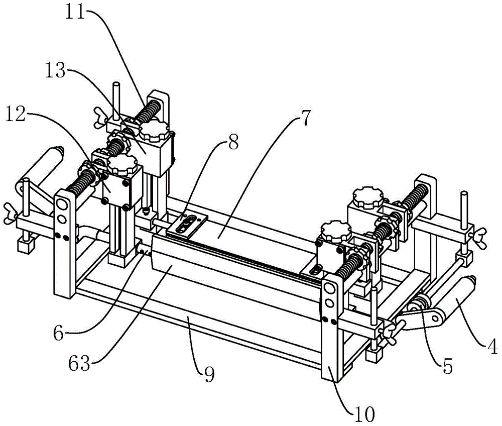
图2是实施例的结构示意图;Fig. 2 is the structural representation of embodiment;
图3是刷镀腔中的结构示意图;FIG. 3 is a schematic view of the structure in the brush plating chamber;
图4是刷镀管的结构示意图;Fig. 4 is the structural representation of brush plating tube;
图5是限位机构的结构示意图;Fig. 5 is the structural schematic diagram of the limit mechanism;
图6是第一支座与第二支座的结构示意图。FIG. 6 is a schematic structural diagram of the first support and the second support.
图中,100、电镀条;101、凸起;1、机架;2、入口;3、出口;4、压紧轮;5、导向轮;6、刷镀管;61、刷镀孔;62、支撑架;63、刷镀布;7、接触板;71、接触槽;8、限位板;81、移动槽;82、限位螺栓;9、基座;10、竖座;11、第二螺杆;12、第一支座;13、第二支座;131、底座;132、第一螺杆;133、滑动座;134、调节螺母。In the figure, 100, electroplating strip; 101, protrusion; 1, frame; 2, inlet; 3, outlet; 4, pressing wheel; 5, guide wheel; 6, brush plating tube; 61, brush plating hole; 62 , support frame; 63, brushed cloth; 7, contact plate; 71, contact groove; 8, limit plate; 81, moving groove; 82, limit bolt; 9, base; 10, vertical seat; 11, first Two screws; 12, the first support; 13, the second support; 131, the base; 132, the first screw; 133, the sliding seat; 134, the adjusting nut.
具体实施方式Detailed ways
以下结合附图对本实用新型作进一步详细说明。The present utility model will be described in further detail below in conjunction with the accompanying drawings.
参照图2,为本实用新型公开的一种电镀条刷镀装置,包括机架1,机架1的两侧开设有圆形的通孔,其中一侧为入口2,另一侧为出口3,入口2和出口3之间为刷镀腔。电镀条100从入口2传送进刷镀腔经过刷镀过程然后从出口3传出。Referring to FIG. 2 , the utility model discloses a brush plating device for electroplating strips, comprising a frame 1 , and circular through holes are formed on both sides of the frame 1 , one of which is the
参照图2和图3,入口2和出口3处分别设置有压紧轮4,压紧轮4的一侧还设置有导向轮5,导向轮5的外壁沿着电镀条100的传送方向开设有与电镀条100相适配的凹槽。压紧轮4的作用是对进入和离开刷镀腔的电镀条100进行压紧限位,增加电镀条100的稳定性。导向轮5的作用是对电镀条100的传送进行辅助导向,让电镀条100的传送路径可以沿着刷镀路径进行。2 and FIG. 3, the
参照图3和图4,刷镀腔中沿着从入口2到出口3的方向设置有一个刷镀管6,刷镀管6的两端开口并从两端通入刷镀液,刷镀管6靠近入口2的一侧连接电源的正极从而接入阳极。刷镀管6的外壁开设有若干数量的刷镀孔61使刷镀液可以从刷镀孔61中流出。刷镀管6外壁上固定有一个矩形的支撑架62,支撑架62的设置方向为垂直于刷镀腔底面的方向,刷镀管6与支撑架62包覆有一圈吸水材质的刷镀布63,刷镀布63的两端设置有魔术贴将刷镀布63可以连接成为环状从而稳固在支撑架62上。Referring to Figures 3 and 4, a
参照图3和图5,刷镀管6的一侧与刷镀管6平行的设置有限位机构,限位机构包括接触板7以及设置在接触板7两侧的成对设置的限位板8。接触板7与刷镀布63所正对的端面上开设有与电镀条100接触的接触槽71,限位板8连接电源的负极从而接入阴极,电镀条100经过接触槽71时与接触槽71接触也会带有阴极,然后与刷镀布63接触并完成刷镀过程。Referring to FIGS. 3 and 5 , a limit mechanism is provided on one side of the
参照图5,限位板8上开设有条形的移动槽81,同时接触板7的两端开设有与移动槽81相适配的移动孔并穿设有限位螺栓82。限位板8可以沿着移动槽81方向进行滑动进行位置的调整,然后旋紧限位螺栓82从而将限位块进行限位。限位板8是继导向轮5之后的另一个对电镀条100起到限位导向作用的元件,可以将电镀条100一直限位在限位板8以下进行传送,防止电镀条100在传送过程中发生跳动从而超过接触板7导致刷镀效果不好。Referring to FIG. 5 , a strip-shaped moving
参照图3和图6,刷镀腔中固定有矩形框架的基座9,基座9的两侧成对设置有与刷镀腔底面垂直设置的竖座10,竖座10之间设置有第二螺杆11。第二螺杆11上连接有第一支座12和第二支座13,第一支座12和第二支座13的两侧设置有与第二螺杆11螺纹连接的调节螺母134,转动调节螺母134可以带动第一支座12与第二支座13的线性运动,从而对第一支座12和第二支座13进行位置调节。3 and 6 , a base 9 with a rectangular frame is fixed in the brush plating chamber, two sides of the base 9 are paired with
参照图6,第一支座12和第二支座13包括与刷镀腔底面垂直设置的底座131,底座131悬空不与刷镀腔连接,底座131穿设有与其转动连接的第一螺杆132,第一螺杆132上连接有滑动座133,转动第一螺杆132可以带动滑动座133在第一螺杆132上的线性运动从而调节滑动座133的高度。第一支座12上的滑动座133与刷镀管6连接,第二支座13上的滑动座133与接触板7通过连接杆进行连接。第一支座12与第二支座13的设置让刷镀管6和限位机构可以进行沿着机架1高度方向的调整。Referring to FIG. 6 , the
本实施例的实施原理为:电镀条100从入口2处传入刷镀腔,经过压紧轮4的压紧作用与导向轮5的导向作用,然后经过限位机构并沿着限位机构继续传送,在这个过程中电镀条100的表面与浸满了刷镀液的刷镀布63相接触,刷镀布63连有正极,电镀条100连有负极,此时刷镀液中的离子会附着到电镀条100表面完成刷镀,然后电镀条100在经过出口3侧的导向轮5以及压紧轮4从出口3传出。The implementation principle of this embodiment is as follows: the
本具体实施方式的实施例均为本实用新型的较佳实施例,并非依此限制本实用新型的保护范围,故:凡依本实用新型的结构、形状、原理所做的等效变化,均应涵盖于本实用新型的保护范围之内。The examples of this specific embodiment are all preferred embodiments of the present invention, and are not intended to limit the protection scope of the present invention. Therefore: all equivalent changes made according to the structure, shape and principle of the present invention are not It should be covered within the protection scope of the present invention.
Claims (9)
Priority Applications (1)
| Application Number | Priority Date | Filing Date | Title |
|---|---|---|---|
| CN202020128602.6U CN211546689U (en) | 2020-01-20 | 2020-01-20 | Brush plating device for electroplating strip |
Applications Claiming Priority (1)
| Application Number | Priority Date | Filing Date | Title |
|---|---|---|---|
| CN202020128602.6U CN211546689U (en) | 2020-01-20 | 2020-01-20 | Brush plating device for electroplating strip |
Publications (1)
| Publication Number | Publication Date |
|---|---|
| CN211546689U true CN211546689U (en) | 2020-09-22 |
Family
ID=72492521
Family Applications (1)
| Application Number | Title | Priority Date | Filing Date |
|---|---|---|---|
| CN202020128602.6U Expired - Fee Related CN211546689U (en) | 2020-01-20 | 2020-01-20 | Brush plating device for electroplating strip |
Country Status (1)
| Country | Link |
|---|---|
| CN (1) | CN211546689U (en) |
-
2020
- 2020-01-20 CN CN202020128602.6U patent/CN211546689U/en not_active Expired - Fee Related
Similar Documents
| Publication | Publication Date | Title |
|---|---|---|
| CN108588803B (en) | An electrodeposition device | |
| CN216274434U (en) | Efficient electroplating flying target with plate frame | |
| CN205839167U (en) | A kind of volume to volume vertical continuous electroplating device | |
| KR101602849B1 (en) | Electric planting apparatus with horizontal cell | |
| CN105696046B (en) | Electroplating conductive structure for roll-to-roll material belt horizontal operation | |
| CN207632908U (en) | A kind of electroplating bath for continuous ribbon-like materials | |
| CN110760918A (en) | A coating controllable electroplating system | |
| CN120989694A (en) | A U-shaped busbar electroplating equipment and method for eliminating suspension blind spots | |
| CN114592232A (en) | Integral titanium basket for high-speed steel strip continuous nickel plating unit | |
| CN202610379U (en) | Continuous electrolytic polishing device for nickel tungsten alloy strip | |
| CN206477042U (en) | A kind of aluminium alloy type timber-used anodic oxidation device | |
| CN211420344U (en) | Electroplating system with controllable plating layer | |
| CN208965058U (en) | A kind of ultrasonic wave added electroplanting device | |
| CN208899011U (en) | A kind of electroplating device of pcb plate production | |
| CN216378475U (en) | Device for removing copper plated on conductive roller | |
| CN102888639B (en) | Electrode distance adjustable type microarc oxidation electrode holder | |
| CN206127457U (en) | Rectangle anodic oxidation groove of flow equalizing | |
| CN223800793U (en) | A titanium anode electrostatic coating device | |
| CN115369471A (en) | Electroplating system and method | |
| CN222878128U (en) | Electrode optimization mechanism for battery piece coating equipment | |
| CN222961573U (en) | Electroforming hanger for processing label | |
| CN221918299U (en) | High anticorrosive electroplating equipment of fastener | |
| CN218812156U (en) | Electroplating device for steel coil plate | |
| CN214991956U (en) | Conductive device for continuous electroplating | |
| CN206232833U (en) | A kind of steel wire On-line electrolytic dissolution phosphatization cathode roll |
Legal Events
| Date | Code | Title | Description |
|---|---|---|---|
| GR01 | Patent grant | ||
| GR01 | Patent grant | ||
| CF01 | Termination of patent right due to non-payment of annual fee |
Granted publication date: 20200922 |
|
| CF01 | Termination of patent right due to non-payment of annual fee |