CN211541452U - Rubber floor pressing cutting machine - Google Patents
Rubber floor pressing cutting machine Download PDFInfo
- Publication number
- CN211541452U CN211541452U CN201922436397.XU CN201922436397U CN211541452U CN 211541452 U CN211541452 U CN 211541452U CN 201922436397 U CN201922436397 U CN 201922436397U CN 211541452 U CN211541452 U CN 211541452U
- Authority
- CN
- China
- Prior art keywords
- compression roller
- lower compression
- machine
- cutting tool
- frame
- Prior art date
- Legal status (The legal status is an assumption and is not a legal conclusion. Google has not performed a legal analysis and makes no representation as to the accuracy of the status listed.)
- Active
Links
- 238000005520 cutting process Methods 0.000 title claims abstract description 32
- 238000003825 pressing Methods 0.000 title description 3
- 230000006835 compression Effects 0.000 claims abstract description 45
- 238000007906 compression Methods 0.000 claims abstract description 45
- 230000007246 mechanism Effects 0.000 claims description 13
- 239000003638 chemical reducing agent Substances 0.000 claims description 8
- 230000000712 assembly Effects 0.000 claims 3
- 238000000429 assembly Methods 0.000 claims 3
- 238000004519 manufacturing process Methods 0.000 abstract description 15
- 239000000463 material Substances 0.000 description 6
- 230000005540 biological transmission Effects 0.000 description 2
- 238000000465 moulding Methods 0.000 description 2
- 229920000742 Cotton Polymers 0.000 description 1
- 230000009286 beneficial effect Effects 0.000 description 1
- 230000000903 blocking effect Effects 0.000 description 1
- 230000002860 competitive effect Effects 0.000 description 1
- 230000007547 defect Effects 0.000 description 1
- 230000005611 electricity Effects 0.000 description 1
- 238000000034 method Methods 0.000 description 1
- 230000001681 protective effect Effects 0.000 description 1
- 238000005096 rolling process Methods 0.000 description 1
- 238000010057 rubber processing Methods 0.000 description 1
Images

Landscapes
- Perforating, Stamping-Out Or Severing By Means Other Than Cutting (AREA)
Abstract
The utility model discloses a rubber floor presses shape cutting machine, including the frame, the frame both sides are equipped with the break bar subassembly respectively, and the break bar subassembly overcoat is equipped with the cutting tool area, are equipped with the sharpening component between two break bar subassemblies, the frame on install upper and lower compression roller, upper and lower compression roller one side is equipped with the cutting tool area, the tooth nail on the upper and lower compression roller becomes public female combination range according to the pitch-row, the interval that upper and lower compression roller passes through lifting unit adjustment and cutting tool area, lifting unit passes through component and drive assembly and links to each other, the tooth nail of upper and lower compression roller and the clearance between the tooth nail be 50MM, the diameter of tooth nail is 18MM, the component be formed by universal bearing and integral key shaft connection. The device aims at the characteristics of good toughness, high density and hardness and slow resilience of rubber, increases the compression space by adjusting the distance between the compression roller tooth nail and the tooth nail, realizes complete controllability of rubber compression, reduces product processing loss, ensures normal production, and has the advantages of flow production and high production efficiency.
Description
Technical Field
The utility model relates to a special material cutting device improves design technical field, especially relates to a rubber floor pressure shape cutting machine.
Background
At present, the rubber material is widely applied to ground mats, rubber tracks, sports equipment, protective articles and the like. The manufacturing process of the sports floor rubber is to perform shape treatment on a rubber product to enable the rubber surface to be in a regular shape so as to reduce pressure and increase comfort, is also diversified, and needs an environment-friendly, mechanical, stable and efficient compression device under the condition of protecting the environment. The profiling is generally performed by adjusting the space of a compression roller according to the thickness of the cut rubber and the height of the highest point and the lowest point of the profiling, placing the rubber into the compression roller, compressing the rubber by the compression roller, and cutting the rubber in a state that the rubber is not completely rebounded. The defects of insufficient compression roller strength, cutter band blocking, different finished product depths and large finished product loss when a common molding press works in production.
SUMMERY OF THE UTILITY MODEL
An object of the utility model is to overcome prior art not enough, provide a rubber floor pressure shape cutting machine, to the slow characteristics of the good density hardness high resilience of rubber toughness, through the interval between adjustment compression roller tooth nail and the tooth nail, increase the compression space, realize the complete controllability to the rubber die mould, reduce the product processing consume, ensured the normal clear of production, flow production, production efficiency is high.
In order to achieve the above purpose, the utility model discloses a technical scheme is: the utility model provides a rubber floor die cutting machine, includes the frame, the frame both sides are equipped with the break bar subassembly respectively, and the break bar subassembly overcoat is equipped with the cutting tool area, and the cutting tool outband is equipped with the cutter holder subassembly, is equipped with the subassembly of whetting a knife between two break bar subassemblies, the frame on install upper and lower compression roller, upper and lower compression roller one side is equipped with the cutting tool area, the profile of tooth nail on upper and lower compression roller becomes public female combination range according to the pitch-row, upper and lower compression roller passes through the interval of lifting unit adjustment and cutting tool area, lifting unit passes through the component of force subassembly.
The gap between the teeth of the upper and lower compression rollers is 50MM by 50MM, and the diameter of the teeth is 18 MM.
The component force assembly is formed by connecting a universal bearing and a spline shaft.
The two ends of the upper and lower compression rollers are respectively provided with a lifting component, the lifting components at the two ends are linked through a bevel gear transmission mechanism, and the lifting components are screw rod mechanisms.
The driving assembly comprises a motor and a speed reducing mechanism, and the upper and lower press rollers are driven after being reduced in speed through the motor and the speed reducer.
The knife flywheel of the knife flywheel assembly is arranged on the mounting seat with the sliding plate, and the mounting seat is fixed on the rack.
The sliding plate on the mounting seat is driven by a screw rod mechanism and a hand wheel, and the knife flywheel is driven by a motor after the speed of the motor is reduced by a speed reducer.
Compared with the prior art, the beneficial effects of the utility model are that: the device aims at the characteristics of good toughness, high density and hardness and slow resilience of rubber, increases the compression space by adjusting the distance between the compression roller tooth nail and the tooth nail, realizes complete controllability of rubber compression, reduces product processing loss, ensures normal production, and has the advantages of flow production and high production efficiency.
Drawings
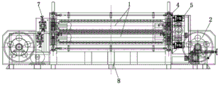
Fig. 1 is a front view of the present invention;
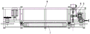
fig. 2 is a top view of the present invention;
fig. 3 is a left side view of the present invention.
The labels in the figures are: 1. an upper press roll and a lower press roll; 2. a cutter wheel assembly; 3. a toolholder assembly; 4. a lifting assembly; 5. a drive assembly; 6. a force component assembly; 7. a sharpening assembly; 8. and a frame.
Detailed Description
The following detailed description is provided to further explain the technical features and advantages of the present invention by referring to the accompanying drawings in combination with the embodiments.
As shown in fig. 1-3, the utility model discloses a rubber floor presses shape cutting machine, including frame 8, the frame both sides are equipped with break bar subassembly 2 respectively, and the break bar subassembly overcoat is equipped with the cutting tool area, and the cutting tool outband is equipped with cutter holder subassembly 3, is equipped with sharpening assembly 7 between two break bar subassemblies, the frame on install upper and lower compression roller 1, upper and lower compression roller one side is equipped with the cutting tool area, the profile peg on upper and lower compression roller becomes public female combination range according to the pitch-row, upper and lower compression roller passes through the interval of 4 adjustments of lifting unit and cutting tool area, lifting unit passes through component subassembly 6 and links to each other with drive assembly 5.
Furthermore, the gap between the teeth of the upper and lower compression rollers is 50MM by 50MM, and the diameter of the teeth is 18 MM. The component force assembly is formed by connecting a universal bearing and a spline shaft. The two ends of the upper and lower compression rollers are respectively provided with a lifting component, the lifting components at the two ends are linked through a bevel gear transmission mechanism, and the lifting components are screw rod mechanisms. The driving assembly comprises a motor and a speed reducing mechanism, and the upper and lower press rollers are driven after being reduced in speed through the motor and the speed reducer. The knife flywheel of the knife flywheel assembly is arranged on the mounting seat with the sliding plate, and the mounting seat is fixed on the rack. The sliding plate on the mounting seat is driven by a screw rod mechanism and a hand wheel, and the knife flywheel is driven by a motor after the speed of the motor is reduced by a speed reducer.
The utility model discloses the device contains the cutter area, and cutter area both sides are taut through the break bar, and the break bar is installed on the mount pad of taking the slide. The upper and lower compression rollers are arranged on the upper and lower sides of the cutter belt, and are driven by toothed nails with the diameter of 18MM to form male and female combinations according to the hole pitch without mutual interference. The upper and lower compression rollers can adjust the distance between the upper and lower compression rollers and the cutting knife belt by adjusting the height of the lifting assembly. The side edges of the upper and lower compression rollers are driven by a motor and are connected by a speed reducer and then are connected by a universal bearing and a spline shaft to drive the upper and lower compression rollers to rotate. The knife sharpening assembly is installed to the cutting knife area side, can revise the cutting edge simultaneously in the cutting, is equipped with behind the upper and lower compression roller and receives the material support, receives the material cylinder rotation linear velocity and is unanimous with the compression roller linear velocity, guarantees the synchronism of rolling. Aiming at the characteristics of good toughness, high density and high hardness and slow rebound of rubber, the compression space is enlarged by adjusting the gap 50 x 50MM between the compression roller tooth nails and the tooth nails, the driving power of the upper and lower compression rollers is strengthened, the self resistance of high-hardness rubber is overcome, a variable-frequency speed-regulating cutting knife belt is additionally arranged, the rubber with different hardness and thickness is properly matched, and the strength of the mounting seat of the knife wheel is strengthened to ensure the running stability of the cutting knife belt.
The device overcomes the characteristics of rubber which are difficult to process through a mechanical profiling mode, is different from the low precision of the efficiency of a general profiling machine, freely adjusts the cutting speed and the cotton pressing speed during profiling, strengthens the strength and the functionality of each main part, realizes complete controllability of rubber profiling, realizes flow production, reduces the product processing loss, and ensures the normal running of production and high production efficiency. The profiling structure has reasonable design, compact structure, stable operation, safety, reliability and convenient use, and can profile the rubber material creatively; the device has long service life and high processing precision, can ensure different compression precision when rubber products are molded, has stable operation of the whole die and accurate shape and size of the products, and effectively ensures the molding quality of the products; the design structure of the product can be simplified, the profiling structure is simpler, the rubber processing is easy, the design cost and the manufacturing cost of the product are reduced, and the overall competitive advantage of the product is improved.
The utility model discloses in the device, the motor that involves and reduction gears, bevel gear drive mechanism and screw mechanism are prior art or material, and affiliated technical staff can directly purchase or order from the market according to required product model and specification.
The electrical components are electrically connected with an external master controller and industrial electricity, and the master controller can be a conventional known device for controlling a computer and the like.
It will be understood that when an element is referred to as being "secured to" another element, it can be directly on the other element or intervening elements may also be present. When an element is referred to as being "mounted on" another element, it can be directly mounted on the other element or intervening elements may also be present. When an element is referred to as being "connected" to another element, it can be directly connected to the other element or intervening elements may also be present.
The present invention is described in detail in the above embodiments, and it should be understood that the described embodiments are not limited to the embodiments of the present invention. Based on the embodiments in the present invention, all other embodiments obtained by a person skilled in the art without creative work belong to the protection scope of the present invention.
Claims (7)
1. The utility model provides a rubber floor die cutting machine, includes the frame, the frame both sides are equipped with the break bar subassembly respectively, the break bar subassembly overcoat is equipped with the cutting tool area, the cutting tool outband is equipped with the cutter holder subassembly, be equipped with the subassembly of whetting a knife between two break bar subassemblies, its characterized in that, the frame on install upper and lower compression roller, upper and lower compression roller one side is equipped with the cutting tool area, the profile of tooth nail on upper and lower compression roller is arranged according to pitch-row becomes public mother combination, upper and lower compression roller passes through the interval of lifting unit adjustment and cutting tool area, the lifting unit passes through the component subassembly and links.
2. The machine according to claim 1, wherein the gap between the pins of the upper and lower rolls is 50MM by 50MM, and the diameter of the pins is 18 MM.
3. The machine as claimed in claim 1 or 2, wherein the force-dividing assembly is formed by connecting a universal bearing and a spline shaft.
4. The machine as claimed in claim 3, wherein the upper and lower rolls are provided at opposite ends thereof with respective lifting assemblies, the lifting assemblies at opposite ends being coupled by a bevel gear drive mechanism, the lifting assemblies being screw mechanisms.
5. The machine of claim 4, wherein the drive assembly comprises a motor and a speed reducer, and the upper and lower rollers are driven by the motor via the speed reducer.
6. The machine as claimed in claim 5, wherein the cutter wheel of the cutter wheel assembly is mounted on a mounting seat with a sliding plate, and the mounting seat is fixed on the machine frame.
7. The machine of claim 6, wherein the slide plate on the mounting base is driven by a lead screw mechanism and a hand wheel, and the knife wheel is driven by a motor through a speed reducer after speed reduction.
Priority Applications (1)
| Application Number | Priority Date | Filing Date | Title |
|---|---|---|---|
| CN201922436397.XU CN211541452U (en) | 2019-12-30 | 2019-12-30 | Rubber floor pressing cutting machine |
Applications Claiming Priority (1)
| Application Number | Priority Date | Filing Date | Title |
|---|---|---|---|
| CN201922436397.XU CN211541452U (en) | 2019-12-30 | 2019-12-30 | Rubber floor pressing cutting machine |
Publications (1)
| Publication Number | Publication Date |
|---|---|
| CN211541452U true CN211541452U (en) | 2020-09-22 |
Family
ID=72511459
Family Applications (1)
| Application Number | Title | Priority Date | Filing Date |
|---|---|---|---|
| CN201922436397.XU Active CN211541452U (en) | 2019-12-30 | 2019-12-30 | Rubber floor pressing cutting machine |
Country Status (1)
| Country | Link |
|---|---|
| CN (1) | CN211541452U (en) |
Cited By (1)
| Publication number | Priority date | Publication date | Assignee | Title |
|---|---|---|---|---|
| CN114030024A (en) * | 2021-12-09 | 2022-02-11 | 泰兴市双羊机械工程有限公司 | Full-automatic splitting machine |
-
2019
- 2019-12-30 CN CN201922436397.XU patent/CN211541452U/en active Active
Cited By (1)
| Publication number | Priority date | Publication date | Assignee | Title |
|---|---|---|---|---|
| CN114030024A (en) * | 2021-12-09 | 2022-02-11 | 泰兴市双羊机械工程有限公司 | Full-automatic splitting machine |
Similar Documents
| Publication | Publication Date | Title |
|---|---|---|
| CN2933791Y (en) | Bamboo strip splitting machine | |
| CN201565506U (en) | Fully-automatic high-speed multifunctional wave shape pressing machine | |
| CN219114148U (en) | Glass wool board cutting machine | |
| CN116237408B (en) | Machining machine for mechanical forming manufacturing | |
| CN208698007U (en) | The welding of ultrasonic wave eyeshade machine and rolling cut combination unit | |
| CN222890459U (en) | Lining plate forming device | |
| CN212887756U (en) | Cutting die | |
| CN210854650U (en) | Anti-slip type slitting machine for film guiding production | |
| CN217885251U (en) | Hydraulic cutting machine for shoemaking | |
| CN208555607U (en) | A kind of steel strip stamping equipment with bearing material function | |
| CN215881773U (en) | Full-automatic guillootine | |
| CN215918731U (en) | Wind wheel blade rolling forming machine | |
| CN213317316U (en) | Continuous stamping die for processing metal plate | |
| CN112873412B (en) | Die-cut device of chip is used in electronic product processing | |
| CN211278634U (en) | Feeding device for cutting packaged printed matter | |
| CN108481413B (en) | Rack and pinion transmission receiving device for die cutting machine | |
| CN210995818U (en) | Fixed direction frock of rolling of mould steel | |
| CN2176227Y (en) | Automatic machine for shaping decorative wood line | |
| CN200951591Y (en) | Multiple feeding banboo wood hobbing cutting bar miller | |
| CN212372259U (en) | Cutting device is used in processing of silica gel board | |
| CN113684673A (en) | Underwear edge cutting machine with waste gathering structure and using method thereof | |
| CN215467179U (en) | Discharging assembly for die-cutting machine | |
| CN218835750U (en) | Continuous pressure boost calendering device of belted steel | |
| CN220112454U (en) | A shearing machine with a plate fixed structure | |
| CN113442224A (en) | Using method of IaLny composite flat die cutting machine |
Legal Events
| Date | Code | Title | Description |
|---|---|---|---|
| GR01 | Patent grant | ||
| GR01 | Patent grant |